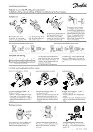
DHP-A, AL, C, H, L Installation instructions - Danfoss.com
DHP-A, AL, C, H, L Installation instructions - Danfoss.com
DHP-A, AL, C, H, L Installation instructions - Danfoss.com

You also want an ePaper? Increase the reach of your titles
YUMPU automatically turns print PDFs into web optimized ePapers that Google loves.
<strong>Installation</strong> <strong>instructions</strong><br />
<strong>DHP</strong>-A<br />
<strong>DHP</strong>-A Opti<br />
<strong>DHP</strong>-<strong>AL</strong><br />
<strong>DHP</strong>-<strong>AL</strong> Opti<br />
<strong>DHP</strong>-C<br />
<strong>DHP</strong>-H<br />
<strong>DHP</strong>-H Opti<br />
<strong>DHP</strong>-H Opti Pro<br />
<strong>DHP</strong>-L<br />
<strong>DHP</strong>-L Opti<br />
<strong>DHP</strong>-L Opti Pro<br />
VMBMA1002
If these <strong>instructions</strong> are not followed during installation and<br />
service, <strong>Danfoss</strong> A/Sliability according to the applicable warranty<br />
is not binding. <strong>Danfoss</strong> A/S retains the right to make changes to<br />
<strong>com</strong>ponents and specifications without prior notice.<br />
© 2010 Copyright <strong>Danfoss</strong> A/S.<br />
The Swedish language is used for the original <strong>instructions</strong>. Other<br />
languages are a translation of original <strong>instructions</strong>.<br />
(Directive 2006/42/EG)
Contents<br />
1 About documents and decals....................................................... 3<br />
1.1 Introduction..................................................................................... 3<br />
1.2 Symbols in documents................................................................. 3<br />
1.3 Symbols on decals......................................................................... 3<br />
2 Important information/Safety regulations............................... 6<br />
2.1 Refrigerant........................................................................................ 7<br />
2.2 Electrical connection..................................................................... 8<br />
2.3 Commissioning............................................................................... 8<br />
3 Heat pump data, dimensions and connections................... 10<br />
3.1 <strong>DHP</strong>-H, <strong>DHP</strong>-H Opti..................................................................... 10<br />
3.2 <strong>DHP</strong>-H Opti Pro............................................................................. 10<br />
3.3 <strong>DHP</strong>-C............................................................................................... 11<br />
3.4 <strong>DHP</strong>-L, <strong>DHP</strong>-L Opti....................................................................... 11<br />
3.5 <strong>DHP</strong>-L Opti Pro.............................................................................. 12<br />
3.6 <strong>DHP</strong>-A, <strong>DHP</strong>-A Opti..................................................................... 12<br />
3.7 <strong>DHP</strong>-<strong>AL</strong>, <strong>DHP</strong>-<strong>AL</strong> Opti................................................................. 13<br />
3.8 Outdoor unit <strong>DHP</strong>-A, <strong>DHP</strong>-<strong>AL</strong>, <strong>DHP</strong>-A Opti, <strong>DHP</strong>-<strong>AL</strong> Opti. 14<br />
4 Transport, unpacking and setting-up...................................... 15<br />
4.1 Transporting the heat pump................................................... 15<br />
4.2 Unpacking heat pump............................................................... 15<br />
4.3 Setting-up the heat pump........................................................ 15<br />
4.4 Setting-up the outdoor unit.................................................... 17<br />
5 Piping installation........................................................................... 22<br />
5.1 Safety valves.................................................................................. 22<br />
5.2 Connection heat transfer fluid................................................ 23<br />
5.3 Connection brine......................................................................... 33<br />
5.4 Noise information........................................................................ 36<br />
6 Electrical <strong>Installation</strong>...................................................................... 38<br />
6.1 Electrical <strong>com</strong>ponents............................................................... 38<br />
6.2 Fuse size.......................................................................................... 38<br />
6.3 Connecting external supply voltage.................................... 39<br />
6.4 Position and connect outdoor sensors................................ 40<br />
6.5 Connect outdoor unit, <strong>DHP</strong>-A, <strong>DHP</strong>-<strong>AL</strong>............................... 41<br />
6.6 Connect temperature sensor hot water, <strong>DHP</strong>-L............... 41<br />
6.7 Changing the language in the control <strong>com</strong>puter............ 41<br />
6.8 Selection of system solution and connection of external aux. heater. 42<br />
6.9 Changing the number of auxiliary heating power stages. 44<br />
7 Menu information........................................................................... 45<br />
8 INFORMATION menu..................................................................... 46<br />
8.1 Sub-menu OPERAT...................................................................... 47<br />
8.2 Sub-menu HEAT CURVE............................................................ 48<br />
8.3 Sub-menu HEAT CURVE 2......................................................... 48<br />
8.4 Sub-menu TEMPERATURE........................................................ 49<br />
8.5 Sub-menu OPERAT.TIME........................................................... 49<br />
8.6 Sub-menu DEFROST................................................................... 49<br />
8.7 Sub-menu LANGUAGE............................................................... 50<br />
9 SERVICE menu................................................................................... 51<br />
9.1 Sub-menu HOT WATER.............................................................. 54<br />
9.2 Sub-menu HEAT PUMP.............................................................. 54<br />
9.3 Sub-menu AUX. HEATER........................................................... 55<br />
9.4 Sub-menu MANU<strong>AL</strong> TEST......................................................... 56<br />
9.5 Sub-menu INST<strong>AL</strong>LATION........................................................ 58<br />
9.6 Sub-menu DEFROST................................................................... 60<br />
9.7 Sub menu OPTIMUM.................................................................. 60<br />
9.8 Sub-menu HGW............................................................................ 61<br />
10 Commissioning.............................................................................. 63<br />
10.1 Filling the water heater and heating system................... 63<br />
10.2 Bleed the heating system....................................................... 63<br />
10.3 Filling the brine system........................................................... 63<br />
10.4 Bleed the brine circuit.............................................................. 65<br />
10.5 Bleed the outdoor unit............................................................ 65<br />
10.6 Start up.......................................................................................... 66<br />
10.7 Commissioning.......................................................................... 69<br />
10.8 Trimming the heating system.............................................. 70<br />
10.9 Customer information............................................................. 71<br />
VMBMA1002 – 1
1 About documents and decals<br />
1.1 Introduction<br />
The following documents are available for this product:<br />
• <strong>Installation</strong> <strong>instructions</strong> containing information to install and <strong>com</strong>mission a heat pump installation. Supplied<br />
with the heat pump on delivery.<br />
• The service <strong>instructions</strong> contain information about the heat pump’s function, accessories, fault tracing and<br />
technical data. The <strong>instructions</strong> also contain tips and advice that should be followed before a heat pump<br />
installation. It is therefore re<strong>com</strong>mended that the <strong>instructions</strong> are read before installation.<br />
The service <strong>instructions</strong> are available for download as below.<br />
• The electrical <strong>instructions</strong> that contain the wiring diagram for the heat pump intended for fault tracing and<br />
service. The electrical <strong>instructions</strong> are available for download as below.<br />
• The maintenance <strong>instructions</strong> must handed over and gone through with the end customer. Supplied with the<br />
heat pump on delivery.<br />
• Country specific <strong>instructions</strong> and forms are available where relevant. Supplied with the heat pump on delivery.<br />
• Self-adhesive decals with translation text. Must be placed on the manufacturing plate in conjunction with<br />
installation. Supplied with the heat pump on delivery.<br />
The Service <strong>instructions</strong> and Electrical <strong>instructions</strong> are available for download here:<br />
www.documentation.heatpump.danfoss.<strong>com</strong><br />
1.2 Symbols in documents<br />
The <strong>instructions</strong> contain different warning symbols, which, together with text, indicate to the user that there are<br />
risks involved with actions to be taken.<br />
The symbols are displayed to the left of the text and three different symbols are used to indicate the degree of<br />
danger:<br />
DANGER! Indicates an immediate danger that leads to fatal or serious injury if necessary measures are not<br />
taken.<br />
Warning! Risk of personal injury!Indicates a possible danger that can lead to fatal or serious injury if<br />
necessary measures are not taken.<br />
Caution! Risk of installation damage.Indicates a possible hazard that can lead to item damage if necessary<br />
measures are not taken.<br />
A fourth symbol is used to give practical information or tips on how to perform a procedure.<br />
Note! Information regarding making the handling of the installation easier or a possible operational<br />
technical disadvantage.<br />
1.3 Symbols on decals<br />
The following symbols can occur on decals on the different parts of the heat pump. Which symbols are used<br />
depends on the heat pump model.<br />
<strong>Installation</strong> <strong>instructions</strong> VMBMA1002 – 3
!<br />
!<br />
Electrical <strong>com</strong>ponents<br />
Warning, danger!<br />
Read the documentation provided.<br />
Read the documentation provided.<br />
Warning, hazardous electrical voltage!<br />
Warning, hot surfaces!<br />
Warning, moving parts!<br />
Warning, risk of crushing injury!<br />
Component, normal Component, accessory<br />
3 Outdoor unit 353 Drip tray<br />
50 Outdoor sensor 362 Shunt valve<br />
54 Hot water sensor 406 Room sensor<br />
55 Sensor hot-water top 408 EVU<br />
71 Flow guard 417 Defrost sensor<br />
4 – <strong>Installation</strong> <strong>instructions</strong> VMBMA1002
Pipe connections<br />
Tap water<br />
Heating system<br />
Brine<br />
Defrosting tank<br />
Expansion tank with safety valve, brine<br />
Bleeding<br />
Temperature and pressure relief valve<br />
Outdoor unit<br />
Water heater<br />
<strong>Installation</strong> <strong>instructions</strong> VMBMA1002 – 5
2 Important information/Safety regulations<br />
Warning! Risk of personal injury! Children are not permitted to play with the product.<br />
Warning! As the water temperature in <strong>DHP</strong>-H Opti Pro and <strong>DHP</strong>-L Opti Pro be<strong>com</strong>es extremely hot, a<br />
mixer valve must be installed between the cold water and hot water pipes to ensure a lower domestic hot<br />
water temperature.Alternatively the maximum hot water temperature must be reduced in the Service<br />
menu.<br />
Warning! <strong>Danfoss</strong> SP (1-phase) heat pumps have a factory installed safety valve for temperature and<br />
pressure, (10 bar 90-95°C), in accordance with the requirements in Great Britain. This valve is located in the<br />
water tank and may not be used for any purpose other than connecting the outlet pipe.<br />
Also note that for heat pump <strong>DHP</strong>-H Opti Pro SP and <strong>DHP</strong>-L Opti Pro SP it is imperative that the hot water<br />
temperature is changed from default setting 95°C to 85°C.<br />
Caution! The heat pump must be installed by authorised installation engineers and the installation must<br />
follow the applicable local rules and regulations as well as these installation <strong>instructions</strong>.<br />
Caution! This product is not intended for persons (including children) with reduced physical, sensory or<br />
psychological capacity, or who do not have knowledge or experience, unless supervised or they have<br />
received <strong>instructions</strong> on how the apparatus functions from a safety qualified person.<br />
Caution! The heat pump must be located in a frost-free environment!<br />
Caution! The heat pump must be placed in an area with a floor drain.<br />
Caution! The heat pump must be located on a stable base. The floor must be able to support the gross<br />
weight of the heat pump with filled hot water tank (see Technical data).<br />
Caution! To prevent leaks, ensure that there are no stresses in the connecting pipes!<br />
Caution! It is important that the heating system is bled after installation.<br />
Caution! Bleed valves must be installed where necessary.<br />
6 – <strong>Installation</strong> <strong>instructions</strong> VMBMA1002
2.1 Refrigerant<br />
Caution! The hot water tank must be equipped with an approved safety valve.<br />
Caution! Heating systems with closed expansion tanks must also be supplied with approved pressure<br />
gauges and safety valves.<br />
Caution! Cold and hot water pipes and overflow pipes from safety valves must be made of heat resistant<br />
and corrosion-resistant material, e.g. copper. The safety valve overflow pipes must have an open<br />
connection to the drain and visibly flow into this in a frost-free environment.<br />
Caution! The connecting pipe between the expansion tank and the safety valve must slope continuously<br />
upwards. A continuous upwards slope means that the pipe must not slope downwards from the<br />
horizontal at any point.<br />
Note! If there is any risk of groundwater infiltration at wall lead-ins for brine pipes, watertight grommets<br />
must be used.<br />
Note! In addition to applicable local rules and regulations the installation should be carried out in a<br />
manner that prevents vibrations from the heat pump being transmitted into the house causing noise.<br />
Caution! Work on the refrigerant circuit must only be carried out by a certified engineer!<br />
Although the heat pump cooling system (refrigerant circuit) is filled with a chlorine-free and environmentallyapproved<br />
refrigerant that will not affect the ozone layer, work on this system may only be carried out by authorized<br />
persons.<br />
2.1.1 Fire risk<br />
The refrigerant is not <strong>com</strong>bustible or explosive in normal conditions.<br />
2.1.2 Toxicity<br />
In normal use and normal conditions the refrigerant has low toxicity. However, although the toxicity of the refrigerant<br />
is low, it can cause injury (or be highly dangerous) in abnormal circumstances or where deliberately abused.<br />
Warning! Risk of personal injury! Spaces in which heavy vapour can collect below the level of the air must<br />
be well ventilated.<br />
Refrigerant vapour is heavier than air and, in enclosed spaces below the level of a door for example, and in the<br />
event of leakage, concentrations can arise with a resultant risk of suffocation due to a lack of oxygen.<br />
<strong>Installation</strong> <strong>instructions</strong> VMBMA1002 – 7
Warning! Risk of personal injury! Refrigerant exposed to a naked flame creates a poisonous irritating gas.<br />
This gas can be detected by its odour even at concentrations below its permitted levels. Evacuate the area<br />
until it has been sufficiently ventilated.<br />
2.1.3 Work on the refrigerant circuit<br />
Caution! When repairing the refrigerant circuit, the refrigerant must not be released from the heat pump,<br />
it must treated in the appropriate way.<br />
Draining and refilling must only be carried out using new refrigerant (for the amount and type of refrigerant see<br />
manufacturer’s plate) through the service valves.<br />
2.1.4 Scrapping<br />
Caution! All warranties from <strong>Danfoss</strong> are void if, when filling with refrigerant other than <strong>Danfoss</strong> A/S<br />
specified refrigerant, if there has not been written notification that the new refrigerant is an approved<br />
replacement refrigerant together with other remedies.<br />
Caution! When the heat pump is to be scrapped the refrigerant must be extracted for disposal. Local rules<br />
and regulations related to the disposal of refrigerant must be followed.<br />
2.2 Electrical connection<br />
2.3 Commissioning<br />
Caution! Electrical installation may only be carried out by an authorized electrician and must follow<br />
applicable local and national regulations.<br />
Caution! The electrical installation must be carried out using permanently routed cables. It must be<br />
possible to isolate the power supply using an all-pole circuit breaker with a minimum contact gap of 3<br />
mm. (The maximum load for externally connected units is 2A).<br />
DANGER! Hazardous electrical voltage! The terminal blocks are live and can be highly dangerous due to<br />
the risk of electric shock. All power supplies must be isolated before electrical installation is started. The<br />
heat pump is connected internally at the factory, for this reason electrical installation consists mainly of<br />
the connection of the power supply.<br />
Caution! The installation may only be <strong>com</strong>missioned if the heating system and brine system have been<br />
filled and bled. Otherwise the circulation pumps can be damaged.<br />
8 – <strong>Installation</strong> <strong>instructions</strong> VMBMA1002
Caution! If the installation is only to be driven by an auxiliary heater during the installation, ensure that<br />
the heating system is filled and the brine pump and <strong>com</strong>pressor cannot be started. This is carried out by<br />
setting the operating mode to AUX. HEATER.<br />
<strong>Installation</strong> <strong>instructions</strong> VMBMA1002 – 9
3 Heat pump data, dimensions and connections<br />
3.1 <strong>DHP</strong>-H, <strong>DHP</strong>-H Opti<br />
1845 (±10)<br />
455<br />
596<br />
4<br />
3<br />
110<br />
528<br />
40±10<br />
9<br />
5<br />
6 7<br />
8<br />
440<br />
300<br />
610<br />
80<br />
Figure 1. Dimensions and connections<br />
3.2 <strong>DHP</strong>-H Opti Pro<br />
1845 (±10)<br />
455<br />
596<br />
4<br />
3<br />
110<br />
528<br />
40±10<br />
9<br />
5<br />
6 7<br />
8<br />
440<br />
300<br />
610<br />
80<br />
Figure 2. Dimensions and connections<br />
10 – <strong>Installation</strong> <strong>instructions</strong> VMBMA1002<br />
1<br />
1<br />
2<br />
2<br />
Symbol explanation<br />
1 Brine in, 28 Cu<br />
2 Brine out, 28 Cu<br />
3 Heating system supply pipe, 22 Cu: 4-10 kW, 28 Cu: 12-16 kW<br />
4 Heating system return pipe, 22 Cu: 4-10 kW, 28 Cu: 12-16 kW<br />
5 Connection for bleed valve, 22 Cu<br />
6 Hot water line, 22 mm<br />
7 Cold water line, 22 mm<br />
8 Lead-in for supply, sensor and <strong>com</strong>munication cables<br />
9 Safety valve for temperature and pressure (only applies to<br />
certain models)<br />
The brine pipes can be connected on either the left or right-hand sides<br />
of the heat pump.<br />
Symbol explanation<br />
1 Brine in, 28 Cu<br />
2 Brine out, 28 Cu<br />
3 Heating system supply pipe, 22 Cu: 4-10 kW, 28 Cu:<br />
12-16 kW<br />
4 Heating system return pipe, 22 Cu: 4-10 kW, 28 Cu: 12-16<br />
kW<br />
5 Connection for bleed valve, 22 Cu<br />
6 Hot water line, 22 mm<br />
7 Cold water line, 22 mm<br />
8 Lead-in for supply, sensor and <strong>com</strong>munication cables<br />
9 Safety valve for temperature and pressure (only applies<br />
to certain models)<br />
The brine pipes can be connected on either the left or right-hand sides<br />
of the heat pump.
3.3 <strong>DHP</strong>-C<br />
1845 (±10)<br />
455<br />
596<br />
4<br />
3<br />
110<br />
528<br />
40±10<br />
5<br />
67<br />
8<br />
440<br />
300<br />
610<br />
80<br />
Figure 3. Dimensions and connections<br />
3.4 <strong>DHP</strong>-L, <strong>DHP</strong>-L Opti<br />
1538 (±10)<br />
455<br />
596<br />
3<br />
4<br />
110<br />
528<br />
40±10<br />
5<br />
610<br />
80<br />
440<br />
300<br />
2<br />
1<br />
690<br />
1<br />
2<br />
Symbol explanation<br />
1 Brine in, 28 Cu<br />
2 Brine out, 28 Cu<br />
3 Heating system supply pipe, 22 Cu<br />
4 Heating system return pipe, 22 Cu<br />
5 Connection for bleed valve, 22 Cu<br />
6 Hot water line, 22 mm<br />
7 Cold water line, 22 mm<br />
8 Lead-in for supply, sensor and <strong>com</strong>munication cables<br />
The brine pipes can be connected on either the left or right-hand sides<br />
of the heat pump.<br />
Symbol explanation<br />
1 Brine in, 28 Cu<br />
2 Brine out, 28 Cu<br />
3 Heating system supply pipe, 22 Cu: 4-10 kW, 28 Cu:<br />
12-16 kW<br />
4 Heating system return pipe, 22 Cu: 4-10 kW, 28 Cu: 12-16<br />
kW<br />
5 Lead-in for supply, sensor and <strong>com</strong>munication cables<br />
The brine pipes can be connected on either the left or right-hand sides<br />
of the heat pump.<br />
<strong>Installation</strong> <strong>instructions</strong> VMBMA1002 – 11
3.5 <strong>DHP</strong>-L Opti Pro<br />
1538 (±10)<br />
455<br />
596<br />
40 ±10<br />
6<br />
5<br />
4<br />
110<br />
528<br />
7<br />
610<br />
80<br />
440<br />
300<br />
2<br />
1<br />
690<br />
Figure 4. Dimensions and connections<br />
3.6 <strong>DHP</strong>-A, <strong>DHP</strong>-A Opti<br />
1845 (±10)<br />
455<br />
596<br />
5<br />
4<br />
528<br />
258<br />
40±10<br />
78<br />
9<br />
10<br />
6<br />
300<br />
250<br />
610<br />
80<br />
Figure 5. Dimensions and connections<br />
12 – <strong>Installation</strong> <strong>instructions</strong> VMBMA1002<br />
3<br />
1<br />
2<br />
3<br />
Symbol explanation<br />
1 Return line water heater, 22 (flexible hose)<br />
2 Brine in, 28 Cu<br />
3 Brine out, 28 Cu<br />
4 Heating system supply pipe, 22 Cu: 4-10 kW, 28 Cu: 12-16<br />
kW<br />
5 Heating system return pipe, 22 Cu: 4-10 kW, 28 Cu: 12-16<br />
kW<br />
6 Supply line water heater, 22 Cu<br />
7 Lead-in for supply, sensor and <strong>com</strong>munication cables<br />
The brine lines (2), (3) and return line water heater (1) can be connected<br />
on the right or left-hand sides.<br />
Symbol explanation<br />
1 Brine in, 28 Cu<br />
2 Brine out, 28 Cu<br />
3 Lead-in for supply, sensor and <strong>com</strong>munication cables<br />
4 Heating system supply pipe, 22 Cu: 6-10 kW, 28 Cu: 12 kW<br />
5 Heating system return pipe, 22 Cu: 6-10 kW, 28 Cu: 12 kW<br />
6 Connection for bleed valve, 22 Cu<br />
7 Hot water line, 22 mm<br />
8 Cold water line, 22 mm<br />
9 Expansion outlet brine circuit, R25 int.<br />
10 Safety valve for temperature and pressure (only applies to<br />
certain models)<br />
The brine pipes can be connected on either the left or right-hand sides<br />
of the heat pump.
3.7 <strong>DHP</strong>-<strong>AL</strong>, <strong>DHP</strong>-<strong>AL</strong> Opti<br />
The brine pipes can be connected on either the left or right-hand sides of the heat pump.<br />
1538 (±10)<br />
1<br />
4<br />
455<br />
690<br />
3<br />
40±10<br />
Figure 6. Dimensions and connections heat pump and water heater<br />
Symbol explanation<br />
Heat pump<br />
2<br />
6<br />
5<br />
7<br />
596<br />
9<br />
455<br />
690<br />
1 Brine in, 28 Cu 5 Heating system supply pipe, 22 Cu: 6-10 kW, 28 Cu: 12<br />
kW<br />
2 Brine out, during normal operation, 28 Cu 6 Heating system return pipe, 22 Cu: 6-10 kW, 28 Cu: 12 kW<br />
8<br />
11<br />
40±10<br />
3 Brine out during defrosting to hwh pos 8, 28 Cu 7 Lead-in power and sensor lead<br />
4 Return line from water heater pos 9, 28 Cu<br />
Symbol explanation<br />
Water heater<br />
8 Connection for brine out when defrosting from<br />
pos 3<br />
13 Cold water line, 22 mm<br />
9 Water heater, return pipe to pos 4 14 Supply to water heater coil<br />
10 Bleed valve, at stainless steel water heater 15 Brine, expansion outlet when outdoor unit is positioned at<br />
high level<br />
11 Brine out during defrosting, 28 Cu 16 Lead-in sensor lead<br />
12 Hot water line, 22 mm 17 Safety valve for temperature and pressure (only applies to<br />
certain models)<br />
15<br />
17<br />
14<br />
13<br />
12<br />
<strong>Installation</strong> <strong>instructions</strong> VMBMA1002 – 13<br />
10<br />
16
3.8 Outdoor unit <strong>DHP</strong>-A, <strong>DHP</strong>-<strong>AL</strong>, <strong>DHP</strong>-A Opti, <strong>DHP</strong>-<strong>AL</strong> Opti<br />
910<br />
1<br />
120<br />
441 342<br />
2<br />
300<br />
405<br />
Figure 7. Outdoor unit, dimensions and connections.<br />
Symbol explanation<br />
1 Brine in, 28 Cu<br />
2 Brine out, 28 Cu<br />
14 – <strong>Installation</strong> <strong>instructions</strong> VMBMA1002<br />
1175<br />
2<br />
1<br />
630
4 Transport, unpacking and setting-up<br />
4.1 Transporting the heat pump<br />
Caution! During transportation or lifting of the entire heat pump, the front panel must always be installed<br />
as it locks the other panels construction.<br />
Caution! The heat pump must always be transported and stored in a dry area. Secure the heat pump so<br />
that it cannot tip over during transportation.<br />
When transporting indoors to the installation location it may be necessary to place the heat pump on its back. The<br />
time that the heat pump is transported on its back should be as short as possible. After the heat pump has been<br />
lifted up again it must stand upright for at least an hour before <strong>com</strong>missioning.<br />
4.2 Unpacking heat pump<br />
4.2.1 Delivery check<br />
1. Check that there is no transport damage. The heat pump is packaged in cardboard.<br />
2. Remove the packaging and check that the delivery contains the following <strong>com</strong>ponents.<br />
Part number 4-10 kW 12-16 kW<br />
Safety valve 9 bar 1/2" 086U2369 1 1<br />
Safety valve 1.5 bar 1/2" 086U0896 1 1<br />
Outdoor sensor 086U2701 1 1<br />
Expansion and bleed tank 086U2824 1 1<br />
Rubber bellows for 22-28 mm hole 086U3423 5 5<br />
Flexible hose R20 L=550 086U6033 2 -<br />
Flexible hose R25 L=550 086U6034 - 2<br />
Filler device DN25 086U6006 1 -<br />
Filler device DN32 086U6007 - 1<br />
Dirt filter with shut-off DN20 086U3427 1 -<br />
Dirt filter with shut-off DN25 086U6005 - 1<br />
Manual holder 086U3988 1 1<br />
4.3 Setting-up the heat pump<br />
4.3.1 Re<strong>com</strong>mended location<br />
Caution! To avoid condensation problems for the brine lines, as short a brine line as possible is<br />
re<strong>com</strong>mended indoors.<br />
The heat pump should be located on a stable floor, preferably made of concrete. When locating the heat pump on<br />
a wooden floor this should be reinforced to take the weight of the heat pump including a filled water heater, see<br />
technical data for relevant heat pump. One solution is to place a thick metal plate, at least 6mm, under the heat<br />
pump. The metal plate should cover several joists spreading the weight of the heat pump over a larger area. If the<br />
heat pump is being installed in a newly-built house, this has normally been taken into account during construction,<br />
and the joists where the heat pump will be located have been reinforced. Always check that this has been<br />
carried out when installing into a newly-built house.<br />
<strong>Installation</strong> <strong>instructions</strong> VMBMA1002 – 15
Avoid positioning the heat pump in a corner as the surrounding walls may amplify its noise. It is also important to<br />
adjust the heat pump using the adjustable feet so that it is horizontal to the base.<br />
4.3.2 Space requirement<br />
Caution! The heat pump must not be enclosed as the temperature inside the cabinet be<strong>com</strong>es extremely<br />
high.<br />
To facilitate the installation and subsequent testing and maintenance there must be sufficient free space around<br />
the heat pump in accordance with the following image:<br />
10 mm<br />
300 mm<br />
4.3.3 Setting up<br />
300 mm<br />
300 mm<br />
600 mm<br />
1905<br />
Note! The heat pump has feet that can be adjusted to <strong>com</strong>pensate for irregularities in the surface on<br />
which it is sitting. If the surface is so irregular that the feet cannot <strong>com</strong>pensate for it, the installation<br />
engineer must remedy this.<br />
Note! It is re<strong>com</strong>mended that the condensation drain is installed from the drip tray’s drain pipe by lying<br />
the heat pump down. The drain pipe opens through a hole in the base plate and has a Ø10 mm hose<br />
connection.<br />
Note! If the heat pump has been laid down it is re<strong>com</strong>mended that it stands upright for at least an hour<br />
before <strong>com</strong>missioning.<br />
4.3.4 Removing the front cover<br />
Caution! Do not damage the electrical wiring for the display when the front cover is removed!<br />
16 – <strong>Installation</strong> <strong>instructions</strong> VMBMA1002<br />
1620
To install the heat pump the front cover must be removed.<br />
2<br />
3<br />
1<br />
Figure 8. Removing the front cover<br />
1. Press against the front cover and turn the catch 90° degrees anti-clockwise to release the front cover.<br />
2. Tilt the front cover outwards.<br />
3. Lift the front cover upwards to remove it from the heat pump.<br />
4.4 Setting-up the outdoor unit<br />
Note! Applies to <strong>DHP</strong>-A.<br />
4.4.1 Re<strong>com</strong>mended location<br />
When positioning the outdoor unit, note the following:<br />
Caution! When the outdoor unit is defrosting, water will drip straight down under the unit. The area<br />
around the outdoor unit must therefore be properly drained in order to take the water (approximately 2<br />
litres per defrost).<br />
Caution! The outdoor unit’s adjustable stand must be positioned on a secure base such as wooden<br />
sleepers, paving slabs or cast footings.<br />
Note! The outdoor unit does not have to be positioned in any specific direction.<br />
Note! Noise is produced from the outdoor unit when the fan is in operation, remember this when<br />
positioning to reduce disturbance in your own home as well as to any neighbours.<br />
<strong>Installation</strong> <strong>instructions</strong> VMBMA1002 – 17
4.4.2 Space requirement<br />
300 mm<br />
300 mm<br />
300 mm<br />
Figure 9. Necessary service space for outdoor unit.<br />
1500 mm<br />
4.4.3 Unpacking<br />
The outdoor unit is packed and delivered in a crate.<br />
1. Start by unpacking the unit from the crate.<br />
2. Check that the delivery is <strong>com</strong>plete, it must contain the outdoor unit, front cover, cover as well as a disassembled<br />
stand including necessary screws, nuts and washers.<br />
4.4.4 <strong>Installation</strong><br />
4.4.4.1 Assembling the stand<br />
Assemble the stand<br />
1. Screw the two horizontal struts together (2) using the two ends (1) as illustrated below. Use 10 x M6x10<br />
screws. The curved edges of the horizontal struts must be facing inwards.<br />
1<br />
Figure 10. Assembling the stand<br />
2<br />
2. Screw the adjustable feet (3) into the holes under the ends.<br />
3<br />
1<br />
Symbol explanation<br />
1 Ends<br />
2 Strut<br />
3 Feet<br />
4.4.4.2 Preparing the outdoor unit<br />
While the outdoor unit remains on the pallet it should be prepared for placing on the stand. Carry out the following:<br />
18 – <strong>Installation</strong> <strong>instructions</strong> VMBMA1002
1. There are three M6x20 screws on the lower edge of the outdoor unit. Unscrew them so that 2-3 mm of the<br />
thread remains. Use a torx TX25 screwdriver, or equivalent.<br />
Caution! Do not lift the outdoor unit by its side panels when it is to be raised or moved.<br />
2. Raise the outdoor unit.<br />
3. Remove the side plates. They are held in place by clamps and so are removed by pulling outwards.<br />
4. Remove all four screwed lifting eyes. Use a 13 mm wrench, or equivalent.<br />
4.4.4.3 Assembling the outdoor unit on the stand<br />
1. Lift the outdoor unit into the place on the stand.<br />
2. Screw the outdoor unit onto the stand. Use 4 x M6x20 screws. It may be necessary to push and pull the<br />
stand slightly in order to get the screw holes to align.<br />
Caution! When filling the brine system the outdoor unit must be bled using the bleed screws on<br />
the connecting pipes inside the side covers. We re<strong>com</strong>mend that you return to this instruction after<br />
the brine system has been filled.<br />
3. Reinstall the side panels.<br />
4.4.4.4 Assembling the defrost sensor<br />
Figure 11. Hook the defroster sensor mounting into place<br />
1. Slide the mounting for the defroster sensor into the hole on the reverse of the outdoor unit until the cover<br />
hooks into place on the edge.<br />
2. Take out the defrosting sensor from the electrical connection box. Thread out the sensor through a suitable<br />
lead-in.<br />
3. Route the defroster sensor connection cable through the cable lead-in to the mounting.<br />
4. Secure the defroster sensor at the bottom of the mounting using a cable tie.<br />
4.4.4.5 Assembling the front cover<br />
1. Hook the lower edge of the front cover onto at least one of the three screws in the bottom edge of the<br />
stand.<br />
2. Secure the upper edge of the front panel temporarily in the centre hole. Use 1 x M6x15 torx TX25.<br />
3. Align all the three screws in the lower edge.<br />
4. Screw the three screws in the lower edge fully. Use a torx TX25 screwdriver, or equivalent.<br />
<strong>Installation</strong> <strong>instructions</strong> VMBMA1002 – 19
5. Secure the front panel's upper edge with the 2 x remaining M6x15 torx TX25, see figure below.<br />
Figure 12. Secure the cover<br />
4.4.4.6 Install the cover<br />
1. Hook the cover at the front edge on the front cover.<br />
Figure 13. Hook the front cover into place<br />
1. Secure the cover using a screw on each side. Use 2 x cross head screws.<br />
If the cover does not align with the side cover plates it may be necessary to drill new 3 mm holes:<br />
• Mark for the new holes<br />
• Lift off the cover<br />
• Drill the holes<br />
• Install and screw the cover into place<br />
Figure 14. Screw the front cover into place<br />
20 – <strong>Installation</strong> <strong>instructions</strong> VMBMA1002
4.4.4.7 Install cover<br />
1. Hook the cover onto the stand.<br />
Figure 15. Hook the cover onto the stand.<br />
<strong>Installation</strong> <strong>instructions</strong> VMBMA1002 – 21
5 Piping installation<br />
5.1 Safety valves<br />
Warning! As the water temperature in <strong>DHP</strong>-H Opti Pro and <strong>DHP</strong>-L Opti Pro be<strong>com</strong>es extremely hot, a<br />
mixer valve must be installed between the cold water and hot water pipes to ensure a lower domestic hot<br />
water temperature.Alternatively the maximum hot water temperature must be reduced in the Service<br />
menu.<br />
Warning! <strong>Danfoss</strong> SP (1-phase) heat pumps have a factory installed safety valve for temperature and<br />
pressure, (10 bar 90-95°C), in accordance with the requirements in Great Britain. This valve is located in the<br />
water tank and may not be used for any purpose other than connecting the outlet pipe.<br />
Also note that for heat pump <strong>DHP</strong>-H Opti Pro SP and <strong>DHP</strong>-L Opti Pro SP it is imperative that the hot water<br />
temperature is changed from default setting 95°C to 85°C.<br />
Caution! Piping installation must be carried out in accordance with applicable local rules and regulations.<br />
The hot water tank must be equipped with an approved safety valve.<br />
Caution! To prevent leaks, ensure that there are no stresses in the connecting pipes!<br />
Caution! It is important that the heating system is bled after installation. Bleed valves must be installed<br />
where necessary.<br />
Note! Ensure that the pipe installation is carried out in accordance with the dimensions and connection<br />
diagrams.<br />
Note! Configure the heat pump for the desired system solution in the SERVICE\ADD. HEATER\EXTERN<strong>AL</strong><br />
ADDITION menu.<br />
Caution! Radiator systems with a closed expansion tank must also be equipped with an approved<br />
pressure gauge and safety valve, minimum DN 20, 1.5 bar opening pressure, or according to country<br />
specific requirements.<br />
Caution! Cold and hot water pipes and overflow pipes from safety valves must be made of heat resistant<br />
and corrosion-resistant material, e.g. copper. The safety valve overflow pipes must have an open<br />
connection to the drain and visibly flow into this in a frost-free environment.<br />
Caution! The connecting pipe between the expansion tank and the safety valve must slope continuously<br />
upwards. A continuous upwards slope means that the pipe must not slope downwards from the<br />
horizontal at any point.<br />
22 – <strong>Installation</strong> <strong>instructions</strong> VMBMA1002
5.2 Connection heat transfer fluid<br />
5.2.1 System solution 1<br />
In system solution 1 the heat pump can produce both heating and hot water with the <strong>com</strong>pressor and the integrated<br />
auxiliary heater. Production of heating and hot water cannot occur at the same time because the exchange<br />
valve for heating/hot water is positioned after the auxiliary heater.<br />
The integrated auxiliary heater carries out peak heating charging (antilegionella function) in those operating<br />
modes that permit auxiliary heat.<br />
For system solution 1, select the factory setting in menu SERVICE\AUX. HEATER\EXTERN<strong>AL</strong> ADDITION:<br />
EXTERN<strong>AL</strong> AUX. HEATER = 0 (Off)<br />
REV.V. HOT WATER = INT<br />
5.2.1.1 Example system solution 1<br />
System solution for <strong>DHP</strong>-H, <strong>DHP</strong>-H Opti, <strong>DHP</strong>-H Opti Pro, <strong>DHP</strong>-C, <strong>DHP</strong>-A, <strong>DHP</strong>-A Opti.<br />
Figure 16. Example system solution 1<br />
Symbol explanation<br />
1 Heat pump<br />
10 Supply line<br />
11 Return line<br />
12 Cold water<br />
13 Hot-water<br />
80 Shut-off valve<br />
83 Non-return valve<br />
85 Venting valve<br />
86 Safety valve expansion heating system<br />
87 Safety valve cold water 9 bar<br />
89 Vacuum valve<br />
91 Strainer<br />
96 Flexible hose<br />
113 Expansion heating system<br />
126 Safety valve for temperature and pressure (only<br />
applies to certain models)<br />
<strong>Installation</strong> <strong>instructions</strong> VMBMA1002 – 23
5.2.1.2 Example system solution 1<br />
System solution for <strong>DHP</strong>-L, <strong>DHP</strong>-L Opti<br />
Figure 17. Example system solution 1<br />
24 – <strong>Installation</strong> <strong>instructions</strong> VMBMA1002<br />
Symbol explanation<br />
1 Heat pump<br />
10 Supply line<br />
11 Return line<br />
12 Cold water<br />
13 Hot-water<br />
18 Water heater<br />
80 Shut-off valve<br />
83 Non-return valve<br />
85 Venting valve<br />
86 Safety valve expansion heating system<br />
87 Safety valve cold water 9 bar<br />
89 Vacuum valve<br />
91 Strainer<br />
96 Flexible hose<br />
113 Expansion heating system<br />
126 Safety valve for temperature and pressure (only<br />
applies to certain models)
5.2.1.3 Example system solution 1<br />
System solution for <strong>DHP</strong>-L Opti Pro.<br />
Figure 18. Example system solution 1<br />
5.2.1.4 Example system solution 1<br />
System solution for <strong>DHP</strong>-<strong>AL</strong>, <strong>DHP</strong>-<strong>AL</strong> Opti.<br />
Figure 19. Example system solution 1<br />
Symbol explanation<br />
1 Heat pump<br />
10 Supply line<br />
11 Return line<br />
12 Cold water<br />
13 Hot-water<br />
18 Water heater<br />
80 Shut-off valve<br />
83 Non-return valve<br />
85 Venting valve<br />
86 Safety valve expansion heating system<br />
87 Safety valve cold water 9 bar<br />
89 Vacuum valve<br />
91 Strainer<br />
96 Flexible hose<br />
113 Expansion heating system<br />
126 Safety valve for temperature and pressure<br />
(only applies to certain models)<br />
Symbol explanation<br />
1 Heat pump<br />
10 Supply line<br />
11 Return line<br />
12 Cold water<br />
13 Hot-water<br />
17 Water heater (<strong>DHP</strong>-<strong>AL</strong>)<br />
80 Shut-off valve<br />
83 Non-return valve<br />
85 Venting valve<br />
86 Safety valve expansion heating system<br />
87 Safety valve cold water 9 bar<br />
89 Vacuum valve<br />
91 Strainer<br />
96 Flexible hose<br />
113 Expansion heating system<br />
126 Safety valve for temperature and pressure<br />
(only applies to certain models)<br />
<strong>Installation</strong> <strong>instructions</strong> VMBMA1002 – 25
5.2.2 System solution 2<br />
In system solution 2, the heat pump can produce both heat and hot water and an external auxiliary heater (oil<br />
boiler, electric boiler, district heating or similar) supports heat production but not hot water production. The<br />
exchange valve for heating/hot water is located ahead of the external auxiliary heater, which allows the production<br />
of heating and hot water at the same time.<br />
The integrated auxiliary heater can be used for heating and hot water production as well as for antilegionella. The<br />
values of the integrals, A2 and A3 are used to select if the external auxiliary heater is to step in before or after the<br />
integrated electrical auxiliary heater.<br />
The heat pump control <strong>com</strong>puter also controls an additional shunt located after the external addition.<br />
For system solution 2, select in menu SERVICE\AUX. HEATER\EXTERN<strong>AL</strong> ADDITION:<br />
EXT.AUX.HEATER = ON<br />
REV.V. HOT WATER = INT<br />
5.2.2.1 Example system solution 2<br />
System solution for <strong>DHP</strong>-H, <strong>DHP</strong>-H Opti, <strong>DHP</strong>-H Opti Pro, <strong>DHP</strong>-C, <strong>DHP</strong>-A, <strong>DHP</strong>-A Opti.<br />
Figure 20. Example system solution 2<br />
26 – <strong>Installation</strong> <strong>instructions</strong> VMBMA1002<br />
Symbol explanation<br />
1 Heat pump<br />
10 Supply line<br />
11 Return line<br />
12 Cold water<br />
13 Hot-water<br />
36 Circulation pump<br />
51 Supply line sensor, moved out from heat pump<br />
72 Additional shunt<br />
80 Shut-off valve<br />
83 Non-return valve<br />
85 Venting valve<br />
86 Safety valve expansion heating system<br />
87 Safety valve cold water 9 bar<br />
89 Vacuum valve<br />
91 Strainer<br />
96 Flexible hose<br />
113 Expansion heating system<br />
117 External auxiliary heater<br />
126 Safety valve for temperature and pressure (only<br />
applies to certain models)
5.2.2.2 Example system solution 2<br />
System solution for <strong>DHP</strong>-L, <strong>DHP</strong>-L Opti.<br />
Figure 21. Example system solution 2<br />
Symbol explanation<br />
1 Heat pump<br />
10 Supply line<br />
11 Return line<br />
12 Cold water<br />
13 Hot-water<br />
18 Water heater<br />
36 Circulation pump<br />
51 Supply line sensor, moved out from heat pump<br />
72 Additional shunt<br />
80 Shut-off valve<br />
83 Non-return valve<br />
85 Venting valve<br />
86 Safety valve expansion heating system<br />
87 Safety valve cold water 9 bar<br />
89 Vacuum valve<br />
91 Strainer<br />
96 Flexible hose<br />
113 Expansion heating system<br />
117 External auxiliary heater<br />
126 Safety valve for temperature and pressure (only<br />
applies to certain models)<br />
<strong>Installation</strong> <strong>instructions</strong> VMBMA1002 – 27
5.2.2.3 Example system solution 2<br />
System solution 2 for <strong>DHP</strong>-L Opti Pro.<br />
Figure 22. Example system solution 2<br />
28 – <strong>Installation</strong> <strong>instructions</strong> VMBMA1002<br />
Symbol explanation<br />
1 Heat pump<br />
10 Supply line<br />
11 Return line<br />
12 Cold water<br />
13 Hot-water<br />
18 Water heater<br />
36 Circulation pump<br />
51 Supply line sensor, moved out from heat pump<br />
72 Additional shunt<br />
80 Shut-off valve<br />
83 Non-return valve<br />
85 Venting valve<br />
86 Safety valve expansion heating system<br />
87 Safety valve cold water 9 bar<br />
89 Vacuum valve<br />
91 Strainer<br />
96 Flexible hose<br />
113 Expansion heating system<br />
117 External auxiliary heater<br />
126 Safety valve for temperature and pressure (only applies<br />
to certain models)
5.2.2.4 Example system solution 2<br />
System solution for <strong>DHP</strong>-<strong>AL</strong>, <strong>DHP</strong>-<strong>AL</strong> Opti.<br />
Figure 23. Example system solution 2<br />
Symbol explanation<br />
1 Heat pump<br />
10 Supply line<br />
11 Return line<br />
12 Cold water<br />
13 Hot-water<br />
17 Water heater (<strong>DHP</strong>-<strong>AL</strong>)<br />
36 Circulation pump<br />
51 Supply line sensor, moved out from heat pump<br />
72 Additional shunt<br />
80 Shut-off valve<br />
83 Non-return valve<br />
85 Venting valve<br />
86 Safety valve expansion heating system<br />
87 Safety valve cold water 9 bar<br />
89 Vacuum valve<br />
91 Strainer<br />
96 Flexible hose<br />
113 Expansion heating system<br />
117 External auxiliary heater<br />
126 Safety valve for temperature and pressure (only<br />
applies to certain models)<br />
5.2.3 System solution 3<br />
In system solution 3, the heat pump can produce both heat and hot water and an external auxiliary heater (oil<br />
boiler, district heating or similar) supports heat and hot water production and can support antilegionella. The<br />
exchange valve for heating/hot water is located after the external auxiliary heater, which prevents the production<br />
of heating and hot water at the same time.<br />
The integrated auxiliary heater can be used for heating and hot water production as well as for antilegionella.<br />
The parameter "TOPH.AUX” is used to determine if the external or internal auxiliary heater produces antilegionella.<br />
The values of the integrals, A2 and A3 are used to select if the external auxiliary heater is to step in before or after<br />
the integrated electrical auxiliary heater.<br />
The heat pump control <strong>com</strong>puter also controls an additional shunt located after the external addition.<br />
For system solution 3, select in menu SERVICE\AUX. HEATER\EXTERN<strong>AL</strong> ADDITION:<br />
EXT.AUX.HEATER = ON<br />
REV.V. HOT WATER = EXT<br />
<strong>Installation</strong> <strong>instructions</strong> VMBMA1002 – 29
5.2.3.1 Example system solution 3<br />
System solution for <strong>DHP</strong>-H, <strong>DHP</strong>-H Opti, <strong>DHP</strong>-C, <strong>DHP</strong>-A, <strong>DHP</strong>-A Opti.<br />
Figure 24. Example system solution 3<br />
30 – <strong>Installation</strong> <strong>instructions</strong> VMBMA1002<br />
Symbol explanation<br />
1 Heat pump<br />
10 Supply line<br />
11 Return line<br />
12 Cold water<br />
13 Hot-water<br />
36 Circulation pump<br />
51 Supply line sensor, moved out from heat pump<br />
72 Additional shunt<br />
77 Reversing valve<br />
80 Shut-off valve<br />
83 Non-return valve<br />
85 Venting valve<br />
86 Safety valve expansion heating system<br />
87 Safety valve cold water 9 bar<br />
89 Vacuum valve<br />
91 Strainer<br />
96 Flexible hose<br />
113 Expansion heating system<br />
117 External auxiliary heater<br />
126 Safety valve for temperature and pressure (only<br />
applies to certain models)
5.2.3.2 Example system solution 3<br />
System solution for <strong>DHP</strong>-L, <strong>DHP</strong>-L Opti.<br />
Figure 25. Example system solution 3<br />
Symbol explanation<br />
1 Heat pump<br />
10 Supply line<br />
11 Return line<br />
12 Cold water<br />
13 Hot-water<br />
18 Water heater<br />
36 Circulation pump<br />
51 Supply line sensor, moved out from heat<br />
pump<br />
72 Additional shunt<br />
77 Reversing valve<br />
80 Shut-off valve<br />
83 Non-return valve<br />
85 Venting valve<br />
86 Safety valve expansion heating system<br />
87 Safety valve cold water 9 bar<br />
89 Vacuum valve<br />
91 Strainer<br />
96 Flexible hose<br />
113 Expansion heating system<br />
117 External auxiliary heater<br />
126 Safety valve for temperature and pressure<br />
(only applies to certain models)<br />
<strong>Installation</strong> <strong>instructions</strong> VMBMA1002 – 31
5.2.3.3 Example system solution 3<br />
System solution for <strong>DHP</strong>-<strong>AL</strong>, <strong>DHP</strong>-<strong>AL</strong> Opti.<br />
Figure 26. Example system solution 3<br />
5.2.4 Connecting cold and hot water lines<br />
Symbol explanation<br />
1 Heat pump<br />
10 Supply line<br />
11 Return line<br />
12 Cold water<br />
13 Hot-water<br />
17 Water heater (<strong>DHP</strong>-<strong>AL</strong>)<br />
36 Circulation pump<br />
51 Supply line sensor, moved out from heat<br />
pump<br />
72 Additional shunt<br />
77 Reversing valve<br />
80 Shut-off valve<br />
83 Non-return valve<br />
85 Venting valve<br />
86 Safety valve expansion heating system<br />
87 Safety valve cold water 9 bar<br />
89 Vacuum valve<br />
91 Strainer<br />
96 Flexible hose<br />
113 Expansion heating system<br />
117 External auxiliary heater<br />
126 Safety valve for temperature and pressure<br />
(only applies to certain models)<br />
1. Connect the cold water and hot water pipes with all the necessary <strong>com</strong>ponents according to the connection<br />
diagram for the relevant system.<br />
5.2.5 Connecting the heating system supply and return lines<br />
For information on how flexible hoses should be installed, see Flexible hoses.<br />
1. Connect the supply pipe with a flexible hose connection and with all the necessary <strong>com</strong>ponents.<br />
2. Connect the return pipe with a flexible hose connection and with all the necessary <strong>com</strong>ponents including a<br />
filter.<br />
3. Insulate the supply and return lines.<br />
4. Connect the bleed valve to the outlet (22mm Cu) on the top of the heat pump.<br />
32 – <strong>Installation</strong> <strong>instructions</strong> VMBMA1002
5.3 Connection brine<br />
5.3.1 Connection brine <strong>DHP</strong>-H, <strong>DHP</strong>-H Opti, <strong>DHP</strong>-H Opti Pro, <strong>DHP</strong>-L, <strong>DHP</strong>-L Opti, <strong>DHP</strong>-L Opti Pro<br />
2<br />
1<br />
7<br />
3<br />
4 3<br />
3 3<br />
5<br />
6<br />
Figure 27. General connection diagram brine lines<br />
5.3.2 Connection brine <strong>DHP</strong>-C<br />
1<br />
2<br />
3<br />
3 4 3<br />
3<br />
5<br />
7<br />
Figure 28. General connection diagram brine lines<br />
6<br />
Symbol explanation<br />
1 Brine in<br />
2 Brine out<br />
3 Shut-off valve (part of the filler cock)<br />
4 Dirt valve<br />
5 Safety valve (1.5 bar)<br />
6 Bleed and expansion tank<br />
7 Shut-off valve<br />
Symbol explanation<br />
1 Brine in<br />
2 Brine out<br />
3 Shut-off valve (part of the filler cock)<br />
4 Strainer<br />
5 Safety valve (1.5 bar)<br />
6 Bleed and expansion tank<br />
7 Shut-off valve<br />
5.3.3 Connection brine <strong>DHP</strong>-A, <strong>DHP</strong>-A Opti<br />
If the outdoor unit is installed higher than the heat pump a pressure tank with safety valve must be connected to<br />
the outlet for bleeding.<br />
If the outdoor unit is installed at the same level or lower than the heat pump, the ac<strong>com</strong>panying plastic vessel can<br />
be used. The upper part of the outdoor unit must then not exceed the fluid level in the vessel.<br />
2<br />
1<br />
3<br />
3 4 3<br />
3<br />
7<br />
Figure 29. General connection diagram, brine<br />
lines<br />
5<br />
6<br />
5<br />
8<br />
Symbol explanation<br />
1 Brine in<br />
2 Brine out<br />
3 Shut-off valve (part of the filler cock)<br />
4 Strainer<br />
5 Safety valve (1.5 bar)<br />
6 Bleed and expansion tank<br />
7 Shut-off valve<br />
8 Pressure tank<br />
<strong>Installation</strong> <strong>instructions</strong> VMBMA1002 – 33
5.3.3.1 Connection brine Outdoor unit <strong>DHP</strong>-A, <strong>DHP</strong>-A Opti<br />
3<br />
Figure 30. General connection diagram, brine lines<br />
1<br />
2<br />
Symbol explanation<br />
1 Brine out<br />
2 Brine in<br />
3 Flexible hoses<br />
5.3.4 Connecting brine <strong>DHP</strong>-<strong>AL</strong>, <strong>DHP</strong>-<strong>AL</strong> Opti<br />
If the outdoor unit is installed higher than the heat pump a pressure tank with safety valve must be connected to<br />
the outlet for bleeding.<br />
If the outdoor unit is installed at the same level or lower than the heat pump, the ac<strong>com</strong>panying plastic vessel can<br />
be used. The upper part of the outdoor unit must then not exceed the fluid level in the vessel.<br />
9<br />
10<br />
3 4 3<br />
3 3<br />
Figure 31. General connection diagram, brine lines<br />
Symbol explanation<br />
1 Brine in<br />
2 Brine out<br />
3 Shut-off valve (part of the filler cock)<br />
4 Strainer (part of the filler cock)<br />
5 Safety valve (1.5 bar)<br />
6 Bleed and expansion tank<br />
5.3.5 Drilling holes for brine pipes<br />
7<br />
6<br />
5<br />
11<br />
1<br />
12<br />
2<br />
5<br />
8<br />
7 Shut-off valve<br />
8 Pressure tank<br />
9 Outdoor unit<br />
10 Flexible hoses<br />
11 Bleed valve<br />
12 Moved out supply line sensor, brine<br />
Caution! Ensure that the holes for the insert pipes are positioned so that there is room for the other<br />
installations.<br />
Caution! The brine pipes shall have separate lead-ins. If the wall lead-ins are below the highest ground<br />
water level watertight lead-ins must be used.<br />
34 – <strong>Installation</strong> <strong>instructions</strong> VMBMA1002
The brine pipes must be insulated from the heat pump, through the walls and outside the house all the way to the<br />
collector so as to avoid condensation and prevent heat loss.<br />
If the brine pipes are to be routed above ground, drill holes in the walls for them.<br />
If the brine pipes are to be routed below ground see the <strong>instructions</strong> below.<br />
2<br />
3<br />
3<br />
Figure 32. Making holes<br />
4<br />
1<br />
1<br />
Symbol explanation<br />
1 Insert pipe<br />
2 Brine pipe<br />
3 Mortar<br />
4 Sealant<br />
1. Drill holes in the wall for the insert pipes (1) for the brine pipes. Follow the dimension and connection diagrams.<br />
If there is any risk of groundwater infiltration at brine pipe lead-ins, watertight grommets must be<br />
used.<br />
2. Position the insert pipes (1) in the holes sloping downwards. The inclination must be at least 1cm every<br />
30cm. Cut them at an angle (as illustrated) so that rain water cannot get into the pipes.<br />
3. Insert the brine pipes (2) into the insert pipes in the installation room.<br />
4. Fill in the holes around the lines with mortar (3).<br />
5. Ensure that the brine pipes (2) are centred in the insert pipes (1) so that the insulation is distributed equally<br />
on all sides.<br />
6. Seal the insert pipes (1) with a suitable sealant (foam) (4).<br />
5.3.6 Installing brine pipes<br />
1. Determine to which side the brine pipes are to be connected.<br />
2. Route the out pipe for brine in through the corresponding hole (with rubber collar) in the heat pump side.<br />
3. Install all necessary <strong>com</strong>ponents on the pipe. Remember to install the filler cock with the filter cover<br />
upwards.<br />
4. Route the pipe for brine out through the corresponding hole (with rubber collar) in the heat pump side.<br />
Caution! When the brine lines are connected to the right for <strong>DHP</strong>-A, the brine out line must be routed<br />
over the brine pump, under the <strong>com</strong>pressor’s vacuum pipe and under the condenser’s flexible hose, see<br />
figure below.<br />
<strong>Installation</strong> <strong>instructions</strong> VMBMA1002 – 35
Figure 33. The brine's supply line<br />
1. Install the out pipe with all the ac<strong>com</strong>panying <strong>com</strong>ponents.<br />
2. Install the expansion tank with the safety valve.<br />
3. Fit both brine pipes with anti-diffusion insulation running all the way from the heat pump to the lead-in in<br />
the wall. The brine pipes running outside the house to the collector can be buried, however they must be<br />
well insulated.<br />
Caution! Applies to <strong>DHP</strong>-A:Bear in mind that the outdoor unit may move during defrosts, use<br />
flexible hoses to connect the pipes from the heat pump and pipes on the outdoor unit.<br />
5.3.7 Connection to outdoor unit<br />
Connection for the brine circuit from the heat pump to the outdoor unit can be carried out using pipes or hoses.<br />
Depending on what connection is selected and what diameter the connection has, there is a maximum length that<br />
the connection may be. The maximum lengths in the table below are based on ethylene glycol (which is mixed to<br />
anti-freeze protection down to -32±1°C) at 0°C.<br />
Table 1. Max coil length between heat pump and outdoor unit<br />
<strong>DHP</strong>-A, <strong>DHP</strong>-<strong>AL</strong> Ext.avail.<br />
press.<br />
Size kPa Cu22<br />
Øi = 20.0<br />
6 30 34<br />
(2 x 17)<br />
8 63 21<br />
(2 x 10.5)<br />
10 50 11 *<br />
(2 x 5.5)<br />
12 43 5 *<br />
(2 x 2.5)<br />
Calculated maximum coil length between the HP and outdoor unit, in metres<br />
Cu28<br />
Øi = 25.6<br />
133<br />
(2 x 66.5)<br />
98<br />
(2 x 49)<br />
47<br />
(2 x 23.5)<br />
26<br />
(2 x 13)<br />
PEM DN 25<br />
Øi = 21.0<br />
48<br />
(2 x 24)<br />
30<br />
(2 x 15)<br />
13 *<br />
(2 x 6.5)<br />
8 *<br />
(2 x 4)<br />
*) Not re<strong>com</strong>mended because of high liquid speeds with risk of corrosion/noise problems.<br />
5.4 Noise information<br />
5.4.1 Flexible hoses<br />
PEM DN 32<br />
Øi = 28.0<br />
173<br />
(2 x 86.5)<br />
150<br />
(2 x 75)<br />
78<br />
(2 x 39)<br />
44<br />
(2 x 22)<br />
Caution! The press sleeves may never be used as a counterhold when tightening connections.<br />
All pipes should be routed in such a way that vibrations cannot be transmitted from the heat pump through the<br />
piping and out into the building. This also applies to the expansion pipe. We re<strong>com</strong>mend that flexible hoses are<br />
36 – <strong>Installation</strong> <strong>instructions</strong> VMBMA1002
used for all pipe connections to avoid the transmission of vibrations. Flexible hoses are available to purchase as<br />
accessories. The figures below show how appropriate and inappropriate installations look using this type of hose.<br />
To avoid noise caused by pipe mounting, a rubber-coated pipe clamp should be used to prevent the transmission<br />
of vibrations. However, installation should not be too rigid and the pipe clamp must not be too tight.<br />
Figure 34. Do not twist the flexible hoses as they are installed. At threaded connections, use a counterhold spanner<br />
Figure 35. Cut the hose to the correct length to avoid excess bowing-out or stretching at bends.<br />
Figure 36. Cut the hose to the correct length to avoid excess bowing-out or stretching and offset the ends so that the<br />
hose is installed <strong>com</strong>pletely straight.<br />
Figure 37. Use fixed pipe bends to avoid excess stress on bends next to connections<br />
<strong>Installation</strong> <strong>instructions</strong> VMBMA1002 – 37
6 Electrical <strong>Installation</strong><br />
DANGER! Electrical voltage! The terminal blocks are live and can be highly dangerous due to the risk of<br />
electric shock. All power supplies must be isolated before electrical installation is started. The heat pump<br />
is connected internally at the factory, for this reason electrical installation consists mainly of the<br />
connection of the power supply.<br />
Caution! Electrical installation may only be carried out by an authorized electrician and must follow<br />
applicable local and national regulations.<br />
Caution! The electrical installation must be carried out using permanently routed cables. It must be<br />
possible to isolate the power supply using an all-pole circuit breaker with a minimum contact gap of 3<br />
mm. (The maximum load for externally connected units is 2A).<br />
6.1 Electrical <strong>com</strong>ponents<br />
5<br />
6<br />
7<br />
10<br />
1 2 3<br />
11<br />
Figure 38. The location of the <strong>com</strong>ponents on<br />
the electrical panel<br />
6.2 Fuse size<br />
12<br />
4<br />
8<br />
9<br />
Symbol explanation<br />
1 Terminal block (applies to the expansion card)<br />
2 Terminal block (applies to <strong>DHP</strong>-A)<br />
3 Defrost card (applies to <strong>DHP</strong>-A)<br />
4 Terminal block<br />
5 Space for <strong>Danfoss</strong> Online<br />
6 Warning decal<br />
7 Space for expansion card<br />
8 Motor protection for <strong>com</strong>pressor<br />
9 Automatic fuses<br />
10 Resetting overheating protection<br />
11 Control <strong>com</strong>puter<br />
12 Soft starter card<br />
<strong>DHP</strong>-H, <strong>DHP</strong>-H Opti, <strong>DHP</strong>-H Opti Pro, <strong>DHP</strong>-L, <strong>DHP</strong>-L Opti, <strong>DHP</strong>-L Opti Pro<br />
4 kW 6 kW 8 kW 10 kW 12 kW 16 kW<br />
400V, 3-N A 16 8 /10 1 /10 2 /16 3 10 1 /16 2 /20 3 16 1 /16 2 /20 3 16 1 /16 2 /20 3 16 1 /20 2 /25 3 20 1 /20 2 /25 3<br />
230V, 1-N A 20 1 /25 2 /32 3 25 1 /32 2 /40 3 25 1 /32 2 /40 3 32 1 /40 2 /50 3 32 1 /40 2 /50 3 -<br />
<strong>DHP</strong>-C<br />
6 kW 8 kW 10 kW 4 H 5 H 7 H<br />
400V, 3-N A 10 1 /16 2 /20 3 16 1 /16 2 /20 3 16 1 /16 2 /20 3 10 1 /16 2 /20 3 16 1 /16 2 /20 3 16 1 /16 2 /20 3<br />
38 – <strong>Installation</strong> <strong>instructions</strong> VMBMA1002
<strong>DHP</strong>-A, <strong>DHP</strong>-A Opti, <strong>DHP</strong>-<strong>AL</strong>, <strong>DHP</strong>-<strong>AL</strong> Opti<br />
400V, 3-N A 10 1 /16 2 /20 3 /20 4 /<br />
25 5 /25 6 /30 7<br />
6 kW 8 kW 10 kW 12 kW<br />
16 1 /16 2 /20 3 /20 4 /<br />
25 5 /25 6 /30 7<br />
16 1 /16 2 /20 3 /20 4 /<br />
25 5 /30 6 /35 7<br />
16 1 /20 2 /25 3 /25 4 /<br />
25 5 /30 6 /35 7<br />
230V, 1-N A 25 1 /32 2 /40 3 25 1 /32 2 /40 3 32 1 /40 2 /50 3 32 1 /40 2 /50 3<br />
1. Heat pump with 3 kW immersion heater (1-N 1.5 kW).<br />
2. Heat pump with 6 kW immersion heater (1-N 3 kW).<br />
3. Heat pump with 9 kW immersion heater (1-N 4.5 kW).<br />
4. Heat pump with 12 kW immersion heater and shut off <strong>com</strong>pressor<br />
5. Heat pump with 15 kW immersion heater and shut off <strong>com</strong>pressor<br />
6. Heat pump with 12 kW immersion heater<br />
7. Heat pump with 15 kW immersion heater<br />
8. Fuse phase L1 (size 4 has 1-phase <strong>com</strong>pressor)<br />
6.3 Connecting external supply voltage<br />
DANGER! Electrical voltage! The power cable may only be connected to the terminal block intended for<br />
this purpose. No other terminal blocks may be used!<br />
1. Route the power cable through the opening in the top panel of the heat pump to the terminal blocks.<br />
2. Connect the power cable as follows.<br />
6.3.1 Connection 400 V, 3-N<br />
In<strong>com</strong>ing cable<br />
Circuit-breaker Terminal block heat pump<br />
2 1<br />
4 3<br />
6 5<br />
Figure 39. Connection 400V 3N<br />
N3 3L1 PE5 1L1 1L2 1L3 2L1 2L2 2L3 PE1<br />
<strong>Installation</strong> <strong>instructions</strong> VMBMA1002 – 39
6.3.2 Connection 230 V, 1-N<br />
In<strong>com</strong>ing 230V heat pump<br />
In<strong>com</strong>ing 230V immersion heater<br />
6.3.3 Connection 230 V, 3-P<br />
See country specific electrical <strong>instructions</strong>.<br />
Circuit-breaker Terminal block heat pump<br />
2 1<br />
4 3<br />
2 1<br />
4 3<br />
6.4 Position and connect outdoor sensors<br />
Figure 40. Connection 230V 1N<br />
2/3 x H<br />
H<br />
1L1 N2 PE1<br />
2L1,<br />
2L1<br />
2L1,<br />
2L2<br />
N3 PE4<br />
Re<strong>com</strong>mended location<br />
Unsuitable location<br />
• Position the outdoor sensor on the north or north west side of the house.<br />
• For higher buildings, the sensor should be positioned between the second and third storeys. Its location must<br />
not be <strong>com</strong>pletely protected from the wind but not in a direct draft. The outdoor sensor should not be placed<br />
on reflective panel walls.<br />
• The sensor must be positioned at least 1 m from openings in the walls that emit hot air.<br />
• If the sensor cable is connected through a pipe, the pipe must be sealed so that the sensor is not affected by<br />
outgoing air.<br />
The outdoor sensor is connected by a two core cable. A maximum cable length of 50 m applies for a cross section<br />
of 0.75 mm2. For greater lengths a cross section of 1.5 mm2 is used, up to a maximum of 120 m.<br />
Then connect the sensor to the heat pump’s control system.<br />
Figure 41. Connection outdoor sensor<br />
40 – <strong>Installation</strong> <strong>instructions</strong> VMBMA1002<br />
305 306
6.5 Connect outdoor unit, <strong>DHP</strong>-A, <strong>DHP</strong>-<strong>AL</strong><br />
Caution! The power cable may only be connected to the terminal block intended for this purpose. No<br />
other terminal blocks may be used!<br />
1. Route the power cable through the opening in the top panel of the heat pump to the terminal blocks.<br />
2. Connect the power cable to the terminal block.<br />
Outdoor unit Heat pump Symbol explanation<br />
9<br />
1<br />
2<br />
3<br />
7<br />
8<br />
4<br />
5<br />
6<br />
N/220<br />
211<br />
213<br />
104<br />
218<br />
386<br />
387<br />
125<br />
N/220<br />
126<br />
N/220<br />
127<br />
Figure 42. Connection outdoor unit<br />
PE<br />
220/N<br />
211<br />
213<br />
283<br />
104<br />
218<br />
386<br />
387<br />
6.6 Connect temperature sensor hot water, <strong>DHP</strong>-L<br />
125<br />
1 Neutral<br />
2 Fan high speed<br />
3 Fan low speed<br />
4 Motor protection fan<br />
5 Defrost sensor<br />
6 Accessories<br />
7 Heating, drip tray<br />
8 Heating cable<br />
9 Accessories<br />
Sensor for hot water and hot water peak from external water heater is connected in the following way to <strong>DHP</strong>-L,<br />
<strong>DHP</strong>-L Opti, <strong>DHP</strong>-L Opti Pro.<br />
1<br />
2<br />
311<br />
312<br />
325<br />
326<br />
Figure 43. Connection temperature sensor hot water<br />
6.7 Changing the language in the control <strong>com</strong>puter<br />
Symbol explanation<br />
1. Sensor hot-water<br />
2. Sensor hot-water top<br />
If necessary, change the language in the control <strong>com</strong>puter menu system<br />
1. Ensure that the main circuit breaker is on.<br />
2. Open the INFORMATION menu.<br />
3. Change language in the control <strong>com</strong>puter menu INFORMATION -> LANGUAGE - ENGLISH, select language<br />
with + or -.<br />
<strong>Installation</strong> <strong>instructions</strong> VMBMA1002 – 41
6.8 Selection of system solution and connection of external aux. heater<br />
Note! Configure the heat pump for the desired system solution in the SERVICE\ADD. HEATER\EXTERN<strong>AL</strong><br />
ADDITION menu.<br />
Also see section Piping installation and Menyinformation.<br />
6.8.1 System solution 1<br />
The heat pump is delivered configured for system solution 1.<br />
6.8.2 System solution 2<br />
Note! If necessary the external <strong>com</strong>ponents must be fused using accessory 086U9685 FUSE TO EXTERN<strong>AL</strong><br />
COMPONENT according to the installation <strong>instructions</strong> supplied with the accessory. The tables below give<br />
the <strong>com</strong>ponents referred to.<br />
For system solution 2, select the following in menu SERVICE\AUX. HEATER\EXTERN<strong>AL</strong> ADDITION:<br />
• EXT.AUX.HEATER = ON<br />
• REV.V. HOT WATER = INT<br />
For <strong>DHP</strong>-H, <strong>DHP</strong>-H Opti, <strong>DHP</strong>-H Opti Pro, <strong>DHP</strong>-C the electrical connection for system solution 2 must be carried out<br />
according to the following table:<br />
Table 2. Electrical connection<br />
Component Connection<br />
Internal auxiliary<br />
heater<br />
External auxiliary<br />
heater<br />
I/O-card, output for 6 kW (normal connection)<br />
Additional shunt Terminal block, 215/216<br />
Internal exchange<br />
valve<br />
I/O-card, output for 3 kW, connected and fused with 086U9685<br />
I/O-card, 214 (normal connection)<br />
For <strong>DHP</strong>-L, <strong>DHP</strong>-L Opti, <strong>DHP</strong>-L Opti Pro the electrical connection for system solution 2 must be carried out according<br />
to the following table:<br />
Table 3. Electrical connection<br />
Component Connection<br />
Internal auxiliary<br />
heater<br />
External auxiliary<br />
heater<br />
I/O-card, output for 6 kW (normal connection)<br />
Additional shunt Terminal block, 215/216<br />
Internal exchange<br />
valve<br />
Terminal block 210, connected and fused with 086U9685<br />
I/O-card, 214 (normal connection)<br />
For <strong>DHP</strong>-A, <strong>DHP</strong>-A Opti, <strong>DHP</strong>-<strong>AL</strong>, <strong>DHP</strong>-<strong>AL</strong> Opti the electrical connection for system solution 2 must be carried out<br />
according to the following table:<br />
42 – <strong>Installation</strong> <strong>instructions</strong> VMBMA1002
Table 4. Electrical connection<br />
Component Connection<br />
Internal auxiliary heater I/O-card, output for 3 kW and 6 kW as well as Defrost card, output for 6 kW (normal connections)<br />
External auxiliary heater Defrost card; 283, connected and fused with 086U9685<br />
Additional shunt Terminal block, 215/216<br />
Internal exchange valve I/O-card, 214 (normal connection)<br />
6.8.3 System solution 3<br />
Note! If necessary the external <strong>com</strong>ponents must be fused using accessory 086U9685 FUSE TO EXTERN<strong>AL</strong><br />
COMPONENT according to the installation <strong>instructions</strong> supplied with the accessory. The tables below give<br />
the <strong>com</strong>ponents referred to.<br />
For system solution 3, select the following in menu SERVICE\AUX. HEATER\EXTERN<strong>AL</strong> ADDITION:<br />
• EXT.AUX.HEATER = ON<br />
• REV.V. HOT WATER = EXT<br />
For <strong>DHP</strong>-H, <strong>DHP</strong>-H Opti, <strong>DHP</strong>-C the electrical connection for system solution 3 must be carried out according to the<br />
following table<br />
Table 5. Electrical connection<br />
Component Connection<br />
Internal auxiliary<br />
heater<br />
External auxiliary<br />
heater<br />
I/O-card, output for 6 kW (normal connection)<br />
Additional shunt Terminal block, 215/216<br />
External exchange<br />
valve<br />
I/O-card, output for 3 kW, connected and fused with 086U9685<br />
I/O-card, 214 kW, connected and fused with 086U9685<br />
For <strong>DHP</strong>-L, <strong>DHP</strong>-L Opti the electrical connection for system solution 3 must be carried out according to the following<br />
table:<br />
Table 6. Electrical connection<br />
Component Connection<br />
Internal auxiliary<br />
heater<br />
External auxiliary<br />
heater<br />
I/O-card, output for 6 kW (normal connection)<br />
Additional shunt Terminal block, 215/216<br />
External exchange<br />
valve<br />
Terminal block 210, connected and fused with 086U9685<br />
I/O-card, 214 kW, connected and fused with 086U9685<br />
For <strong>DHP</strong>-A, <strong>DHP</strong>-A Opti, <strong>DHP</strong>-<strong>AL</strong>, <strong>DHP</strong>-<strong>AL</strong> Opti the electrical connection for system solution 3 must be carried out<br />
according to the following table:<br />
<strong>Installation</strong> <strong>instructions</strong> VMBMA1002 – 43
Table 7. Electrical connection<br />
Component Connection<br />
Internal auxiliary heater I/O-card, output for 3 kW and 6 kW as well as Defrost card, output for 6 kW (normal connections)<br />
External auxiliary heater Defrost card; 283, connected and fused with 086U9685<br />
Additional shunt Terminal block, 215/216<br />
External exchange<br />
valve<br />
I/O-card, 214 kW, connected and fused with 086U9685<br />
For system solution 3, the heat pump's integrated exchange valve must be limited in open mode to the heating<br />
system.<br />
To limit the direction of flow for the exchange valve for the heating system, carry out the following steps:<br />
1. Check that the main circuit breaker is on.<br />
2. Open the SERVICE menu by pressing and holding the left button in for five seconds.<br />
3. Open the control <strong>com</strong>puter menu SERVICE -> MANU<strong>AL</strong> TEST.<br />
4. Set the value for MANU<strong>AL</strong> TEST to 1.<br />
5. Set the value for REV.V. HOT WATER to 0.<br />
6. Wait at least 15 seconds, disconnect the quick connector at the exchange valve.<br />
7. Set the value for MANU<strong>AL</strong> TEST back to 0.<br />
8. Connect the external exchange valve cables according to the tables above.<br />
9. Move the supply line sensor out to the position shown in the diagram for System solution 3.<br />
6.9 Changing the number of auxiliary heating power stages<br />
Caution! Setting the maximum permitted number of power stages for the auxiliary heating must be<br />
carried out.<br />
1. Ensure that the main circuit breaker is on.<br />
2. Open the SERVICE menu by pressing and holding in for five seconds.<br />
3. Change the number of auxiliary heating power stages in the control system's menu SERVICE -> AUX.HEAT -<br />
> MAXSTEP, select the number of stages using + and -.<br />
44 – <strong>Installation</strong> <strong>instructions</strong> VMBMA1002
7 Menu information<br />
Menu description regards software with version 1.3.<br />
The heat pump has an integrated control system which automatically calculates the heat demand in the house to<br />
ensure that the correct amount of heat is produced and emitted where necessary.<br />
The control panel is operated using a keypad and information is shown in a display and by an indicator.<br />
Note! The information in the display and menus will vary depending on the heat pump model and<br />
connected accessories.<br />
ROOM<br />
NO HEAT DEMAND<br />
OPERAT. AUTO<br />
20°C 1. Keypad<br />
+ Plus sign used to scroll up a menu and increase the values.<br />
- Minus sign used to scroll down a menu and reduce the values.<br />
> Right arrow used to select a value or open a menu.<br />
< Left arrow to cancel selection or exit a menu.<br />
3<br />
1<br />
2<br />
2. Indicator<br />
3. Display<br />
The indicator at the bottom of the control panel has three modes:<br />
• Not lit, means that the heat pump is not powered.<br />
• When the green light shines continuously, the heat pump has power and is ready to produce heat or hot<br />
water.<br />
• Flashing green, means an active alarm.<br />
Caution! During a service that consists of replacing the display card, all heat pump settings are reset to<br />
factory settings. Therefore note current settings before replacement.<br />
The control system is divided into the following two main menus:<br />
• INFORMATION<br />
• SERVICE<br />
The INFORMATION menu is opened by pressing the left or right buttons.<br />
For installation and service, the SERVICE menu is used, which is opened by pressing the left button for<br />
at least five seconds.<br />
<strong>Installation</strong> <strong>instructions</strong> VMBMA1002 – 45
8 INFORMATION menu<br />
Open the menu by pressing the left or right button. The menu also shows history and operating times.<br />
Note! The menu information below describes all possible parameters. The parameters that appear in the<br />
display vary depending on the selections made in menus (e.g. type of heat pump) and on the connected<br />
hardware (e.g. expansion card and defrost card).<br />
Table 8. Used to change the heat pump's operating modes and to adjust the heat curve.<br />
Menu Sub menu Sub menu Sub menu<br />
INFORMATION<br />
OPERAT.<br />
HEAT CURVE<br />
HEAT CURVE 2 (if shunt group is activated)<br />
TEMPERATURE<br />
OPERAT. TIME<br />
46 – <strong>Installation</strong> <strong>instructions</strong> VMBMA1002<br />
Ø CANCEL<br />
Ø<br />
AUTO<br />
HEAT PUMP<br />
AUX. HEATER<br />
HOT WATER<br />
MANU<strong>AL</strong> TEST<br />
CURVE<br />
MIN<br />
MAX<br />
CURVE 5<br />
CURVE 0<br />
CURVE -5<br />
HEAT STOP<br />
REDUCTION<br />
TANK TEMP<br />
OVERCHARGE<br />
ROOM FACTOR<br />
POOL<br />
POOL HYSTERESIS<br />
CURVE<br />
MIN<br />
MAX<br />
OUTDOOR<br />
ROOM<br />
SYSTEM SUPPLY<br />
SUPPLY LINE<br />
RETURN LINE<br />
BUFFER TANK<br />
HOT WATER<br />
INTEGR<strong>AL</strong><br />
BRINE IN<br />
BRINE OUT<br />
POOL<br />
COOLING<br />
SHUNT GROUP<br />
2ND HEAT CIR.<br />
CURRENT
Menu Sub menu Sub menu Sub menu<br />
DEFROST<br />
LANGUAGE<br />
8.1 Sub-menu OPERAT.<br />
Table 9. Used to select operating mode.<br />
HEAT PUMP<br />
AUX. HEAT 1<br />
AUX. HEAT 2<br />
AUX. HEAT 3<br />
HOT WATER<br />
COOLING<br />
ACT COOLING<br />
DEFROSTS<br />
BETW. 2 DEFR<br />
TIME LAST DEFR<br />
FAN H OFF AT<br />
DEFROST CURVE<br />
MANU<strong>AL</strong> DEFR<br />
SVENSKA<br />
ENGLISH<br />
DEUTSCH<br />
NEDERLANDS<br />
FRANÇAIS<br />
ESPAÑOL<br />
IT<strong>AL</strong>IANO<br />
NORSK<br />
DANSK<br />
SUOMI<br />
EESTI<br />
POLSKI<br />
ČEŠTINA<br />
Menu selection Meaning Factory setting<br />
(OFF)<br />
The installation is fully switched off. This mode is also used to acknowledge certain<br />
alarms.<br />
CANCEL = starting point, no changes made.<br />
To select OFF as operating mode, press the minus sign once to scroll down one<br />
step and press the right arrow once.<br />
AUTO Automatic operation with both heat pump and auxiliary heater permitted. If the<br />
number of power stages for auxiliary heating are set to zero (SERVICE -> AUX.<br />
HEATER -> MAX STEP) only AUTO or OFF can be selected as operating mode.<br />
HEAT PUMP Operation with only heat pump permitted.<br />
Note! No peak heating charging (anti-legionella function) with<br />
only heat pump operation.<br />
AUX. HEATER Operation with only auxiliary heater permitted. -<br />
HOT WATER Operation with heat pump for hot water production and auxiliary heater during<br />
peak heating charging (anti-legionella function).<br />
MANU<strong>AL</strong> TEST Only displayed when the value for MANU<strong>AL</strong> TEST is set to 2 in<br />
The SERVICE menu. Outputs that control <strong>com</strong>ponents are activated manually.<br />
<strong>Installation</strong> <strong>instructions</strong> VMBMA1002 – 47<br />
-<br />
-<br />
-<br />
-<br />
-
8.2 Sub-menu HEAT CURVE<br />
Table 10. Used to change settings for the heat curve.<br />
Menu selection Meaning Factory setting<br />
CURVE Calculated supply temperature at 0°C outdoor temperature. Shown<br />
as a graphic curve. The curve will be limited by the set values of MIN<br />
and MAX.<br />
MIN Minimum permitted supply temperature, if the temperature for heat<br />
stop has been reached and the heat pump has stopped.<br />
40°C<br />
(for under floor heating 30°C)<br />
(range: 22°C / 56°C)<br />
10°C<br />
(range: 10°C / 50°C)<br />
MAX Maximum calculated setpoint value of the supply temperature. 55°C<br />
(for under floor heating 45°C)<br />
(range: 40°C / 85°C)<br />
CURVE +5 Local increase or reduction of CURVE at an outdoor temperature of<br />
+5°C. Shown in the graph for CURVE.<br />
CURVE 0 Local increase or reduction of CURVE at an outdoor temperature of<br />
0°C. Shown in the graph for CURVE.<br />
CURVE -5 Local increase or reduction of CURVE at an outdoor temperature of<br />
-5°C. Shown in the graph for CURVE.<br />
HEAT STOP Maximum outdoor temperature when heat production is permitted.<br />
If HEAT STOP applies, the outdoor temperature must drop 3°C below<br />
the setting before HEAT STOP stops.<br />
REDUCTION Only appears if the tariff control function has been activated. Lowering<br />
set room temperature. Active at 10 kΩ connection at EVU input.<br />
TANK TEMP Displayed if buffer tank is active. Charges the buffer tank to the set<br />
temperature. AUTO setting charges the tank to the supply line setpoint<br />
value.<br />
OVERCHARGE Displayed if the buffer tank is active and TANK TEMP is set to AUTO.<br />
Charges the buffer tank to supply line setpoint value + the value of<br />
OVERCHARGE.<br />
ROOM FACTOR Only displayed if an accessory Room temperature sensor is installed.<br />
Determines how great an impact the room temperature is to have<br />
when calculating the supply temperature. For under floor heating it<br />
is re<strong>com</strong>mended that ROOM FACTOR is set to 1, 2 or 3. For radiator<br />
heating it is re<strong>com</strong>mended that ROOM FACTOR is set to 2, 3 or 4.<br />
POOL Only appears if POOL is selected. The temperature in the pool is controlled<br />
by a separate sensor regardless of the heating and hot water<br />
system.<br />
POOL HYSTERESIS Only appears if POOL is selected. The difference between the desired<br />
charge value (adjustable) and actual value to the pool sensor. Pool<br />
hysteresis does not affect the integral value.<br />
8.3 Sub-menu HEAT CURVE 2<br />
0°C<br />
(range: -5°C / 5°C)<br />
0°C<br />
(range: -5°C / 5°C)<br />
0°C<br />
(range: -5°C / 5°C)<br />
17°C<br />
(range: 0°C / 40°C)<br />
2°C<br />
(range: 1°C / 10°C)<br />
AUTO<br />
(range: 30°C / 55°C)<br />
0°C<br />
(range: 0°C / 5°C)<br />
2<br />
(range: 0 / 4)<br />
(0 = no impact,<br />
4 = very large impact)<br />
20°C<br />
(range: 5°C /40°C)<br />
2°C<br />
(range: 1°C / 10°C)<br />
Only appears if shunt group sensor is connected and activated in menu SERVICE -> INST<strong>AL</strong>LATION -> SYSTEM -><br />
SHUNT GROUP.<br />
Table 11. Used to change settings for heat curve 2.<br />
Menu selection Meaning Factory setting<br />
CURVE 2 Calculated shunt group temperature at 0°C outdoor temperature. Shown as a<br />
graphic curve. The curve will be limited by the set values of MIN and MAX.<br />
MIN Minimum permitted shunt group temperature, if the temperature for heat stop<br />
has not been reached.<br />
40°C<br />
(range: 22°C / 56°C)<br />
10°C<br />
(range: 10°C / 50°C)<br />
MAX Maximum permitted shunt group temperature. 55°C<br />
(range: 15°C / 70°C)<br />
48 – <strong>Installation</strong> <strong>instructions</strong> VMBMA1002
8.4 Sub-menu TEMPERATURE<br />
The history of different temperature measurements can be viewed by pressing the right arrow key. The graph<br />
shows the last 60 measurement points for the set time interval (SERVICE -> INST<strong>AL</strong>LATION -> LOG TIME). In the<br />
event of an alarm, history stops being logged until the alarm is reset by changing the operating mode to OFF.<br />
Table 12. Used to indicate the prevailing temperatures, history and set/calculated values.<br />
Menu selection Meaning Factory setting<br />
OUTDOOR Shows the actual outdoor temperature. -<br />
ROOM Shows the actual set temperature. -<br />
SYSTEM SUPPLY Displays system supply temperature at the buffer tank system. -<br />
SUPPLY LINE Shows the actual supply temperature. The calculated supply temperature to<br />
the heating system group is within brackets.<br />
During hot water production in operating mode AUX. HEATER the value for<br />
HOT WATER STOP + 10° is shown within brackets.<br />
RETURN LINE Shows the actual return temperature. The stop temperature, MAX RETURN is<br />
within brackets.<br />
BUFFER TANK Indicates the buffer tank temperature, if activated. -<br />
HOT WATER Indicates actual hot water temperature, if activated. -<br />
INTEGR<strong>AL</strong> Shows the actual calculated value for integral. -<br />
BRINE IN Shows the actual temperature for brine in. -<br />
BRINE OUT Shows the actual temperature for brine out. -<br />
POOL Only appears if POOL is selected. Shows the actual pool temperature.<br />
The set pool temperature is shown in brackets.<br />
COOLING Indicates temperature.<br />
SHUNT GROUP Only appears if SHUNT GROUP is selected. Shows the actual supply temperature.<br />
The calculated supply temperature to the shunt group is within brackets.<br />
2ND HEAT CIR. Shows the temperature of the second heating circuit if installed by the buffer<br />
tank system.<br />
CURRENT Only appears if CURRENT LIMITER is selected. Shows the actual current consumption.<br />
The set value for MAX CURRENT is shown in brackets.<br />
8.5 Sub-menu OPERAT.TIME<br />
Table 13. Used to show the operating time for each <strong>com</strong>ponent. Time given in hours.<br />
Menu selection Meaning Factory setting<br />
HEAT PUMP Compressor operating time for both heating and hot water production. -<br />
AUX. HEATER Operating time of auxiliary heater. -<br />
HOT WATER Operating time for hot water with <strong>com</strong>pressor. -<br />
8.6 Sub-menu DEFROST<br />
Table 14. Used to obtain information about defrosting settings and to make defrosting settings.<br />
Menu selection Meaning Factory setting<br />
DEFROSTS Total number of defrosts carried out. -<br />
BETW. 2 DEFR The operating time of the <strong>com</strong>pressor in minutes between the<br />
two last defrosts.<br />
TIME LAST DEFR The operating time of the <strong>com</strong>pressor in minutes since last<br />
defrost.<br />
-<br />
-<br />
-<br />
-<br />
-<br />
-<br />
-<br />
<strong>Installation</strong> <strong>instructions</strong> VMBMA1002 – 49
Menu selection Meaning Factory setting<br />
FAN H OFF AT High speed is deactivated at this temperature and low speed is<br />
activated.<br />
DEFROST CURVE Used to change the angle of the defrost curve using + or–<br />
(Change the start temperature for defrost).<br />
12°C<br />
(range: 10°C / 20°C)<br />
-10°C<br />
(range: -13°C / -7°C)<br />
MANU<strong>AL</strong> DEFR Used to perform a manual defrost. Started using + or -. 0<br />
(range: 0 / 1)<br />
8.7 Sub-menu LANGUAGE<br />
Table 15. Used to set the language of the menu system.<br />
Menu selection<br />
SVENSKA<br />
ENGLISH<br />
DEUTSCH<br />
NEDERLANDS<br />
FRANÇAIS<br />
ESPAÑOL<br />
IT<strong>AL</strong>IANO<br />
NORSK<br />
DANSK<br />
SUOMI<br />
EESTI<br />
POLSKI<br />
ČEŠTINA<br />
50 – <strong>Installation</strong> <strong>instructions</strong> VMBMA1002
9 SERVICE menu<br />
The SERVICE menu is for use during installation and service to optimise and adjust the operation of the heat pump.<br />
Open the menu by pressing the left button for five seconds.<br />
Note! The menu information below describes all possible parameters. The parameters that appear in the<br />
display vary depending on the selections made in menus (e.g. type of heat pump) and on the connected<br />
hardware (e.g. expansion card and defrost card).<br />
Table 16. Used to change the heat pump's default settings.<br />
Menu Sub menu Sub menu Sub menu Sub menu<br />
SERVICE<br />
HOT WATER<br />
HEAT PUMP<br />
AUX. HEATER<br />
MANU<strong>AL</strong> TEST<br />
START<br />
HOT WATER TIME<br />
HEATING TIME<br />
TOPH. INTERV<strong>AL</strong><br />
TOPH. TIME<br />
TOPH.STOP<br />
INFL. H.W SENSOR<br />
WEIGHT HOT WATER<br />
INTEGR<strong>AL</strong> A1<br />
HYSTERESIS<br />
MAX RETURN<br />
START INTERV<strong>AL</strong><br />
<strong>AL</strong>ARM BRINE<br />
PRESS. PIPE<br />
OUTDOOR STOP<br />
SHUNT TIME<br />
SHUNT COOLING<br />
MAX STEP<br />
INTEGR<strong>AL</strong> A2<br />
HYSTERESIS<br />
MAX STEP<br />
MAX CURRENT<br />
HOT WATER STOP<br />
DELAY AFTER EVU<br />
EXT.AUX.HEATER<br />
EXT.AUX.HEATER<br />
INTEGR<strong>AL</strong> A3<br />
TURN OFF DELAY<br />
REV.V. HOT WATER<br />
TOPH. AUX<br />
<strong>Installation</strong> <strong>instructions</strong> VMBMA1002 – 51
Menu Sub menu Sub menu Sub menu Sub menu<br />
INST<strong>AL</strong>LATION<br />
52 – <strong>Installation</strong> <strong>instructions</strong> VMBMA1002<br />
MANU<strong>AL</strong> TEST<br />
HEAT PUMP<br />
BRINE PUMP<br />
CIRC. PUMP<br />
REV.V. HOT WATER<br />
SHUNT<br />
SYSTEM SHUNT<br />
HGW-SHUNT<br />
AUX. HEAT 1<br />
AUX. HEAT 2<br />
AUX. HEAT 3<br />
EXT.AUX.HEATER<br />
EXT. CIRC. PUMP<br />
SHUNT DEFR<br />
FAN L<br />
FAN H<br />
EXT. AUX. HEATER<br />
<strong>AL</strong>ARM<br />
SHUNT COOLING<br />
SHUNT GROUP<br />
2ND H.C SHUNT<br />
PASSIVE COOLING<br />
ACT COOLING<br />
REV. V. POOL<br />
0-10V<br />
SYSTEM<br />
HEAT SOURCE<br />
COOLING<br />
POOL<br />
SHUNT GROUP<br />
BUFFER TANK<br />
ADDITION<br />
GROUND OR ROCK<br />
AIR<br />
(BRINE SOLUTION<br />
DIRECT EVAP.)<br />
PASSIVE COOLING<br />
(Ø<br />
EXTERN<strong>AL</strong><br />
INTEGRATED IN HP)<br />
ACT COOLING<br />
(Ø<br />
EXTERN<strong>AL</strong>)<br />
ROOM SENSOR<br />
BUFFER TANK<br />
SYSTEM SHUNT<br />
2ND H.C SHUNT<br />
OPTIMUM<br />
HGW<br />
0-10V<br />
(Ø<br />
EXT. AUX. HEATER)<br />
FLOW SENSOR<br />
CURRENT LIMITER<br />
PHASE FAULT<br />
(Ø<br />
PHASE READING)
Menu Sub menu Sub menu Sub menu Sub menu<br />
DEFROST<br />
OPTIMUM<br />
HGW<br />
SERVICE TIME<br />
FACTORY SET<br />
RESET OPER. TIME<br />
SENSOR C<strong>AL</strong>IBRATION<br />
VERSION<br />
LOG TIME<br />
BRINE TIME ON<br />
BRINE TIME OFF<br />
DEFR CURVE 0<br />
DEFR CURVE -XX<br />
DEFR TEMPERATURE<br />
STOP DEFR<br />
BELOW 5°C DEFR<br />
MIN TIME DEFR<br />
FAN START<br />
FAN STOP<br />
DEFR SENSOR<br />
TEMP DIFF CIRC.<br />
TEMP DIFF BRINE<br />
START FLOW CIRC.<br />
START FLOW BRINE<br />
CONST. FL. CIRC:<br />
CONST. FL. BRINE<br />
MIN FLOW CIRC.<br />
MAX H.W CHARGE HW<br />
MIN CHARGE. HW<br />
HGW TEMPERATURE<br />
TEMPERATURE DIFF<br />
HOT WATER DIFF<br />
HOT WATER TO RAD<br />
MAX TEMPERATURE<br />
START HGW<br />
INITI<strong>AL</strong>IZING HGW<br />
INTEGR<strong>AL</strong> DELAY<br />
HGW-SHUNT TIME<br />
HGW INT. BOUND.<br />
HGW INTEGR<strong>AL</strong><br />
PULSE WIDTH<br />
CANCEL<br />
RADIATOR<br />
FLOOR<br />
OUTDOOR<br />
SUPPLY LINE<br />
RETURN LINE<br />
HOT WATER<br />
BRINE IN<br />
BRINE OUT<br />
DEFR SENSOR<br />
POOL<br />
SHUNT GROUP<br />
HGW TEMPERATURE<br />
BUFFER TANK<br />
2ND HEAT CIR.<br />
SYSTEM SUPPLY<br />
EXTERN<strong>AL</strong> FACTOR<br />
DISPLAY<br />
I/O-CARD<br />
<strong>Installation</strong> <strong>instructions</strong> VMBMA1002 – 53
9.1 Sub-menu HOT WATER<br />
Table 17. Used to change the settings for hot water production.<br />
Menu selection Meaning Factory setting<br />
START Start temperature for hot water production. Shows the actual<br />
weighted hot water temperature and the value within brackets<br />
indicates the start temperature. ( = no hot water production)<br />
HOT WATER TIME Time for hot water production during <strong>com</strong>bined hot water and<br />
heating demand, in minutes.<br />
TOPH. TIME Time in hours that the legionella demand is to be fulfilled for<br />
legionella operation to be considered <strong>com</strong>plete.<br />
HEATING TIME Time for hot water production during <strong>com</strong>bined heating and hot<br />
water demand, in minutes.<br />
TOPH. INTERV<strong>AL</strong> Time interval between peak heating chargings (anti-legionella<br />
function) in days. Operating mode that permits auxiliary heater<br />
must be selected.<br />
TOPH. STOP Stop temperature for peak heat charging. Operating mode that<br />
permits auxiliary heater must be selected.<br />
INFL. H.W SENSOR. Water heater sensor’s influence <strong>com</strong>pared with the peak sensor’s at<br />
start of water heating.<br />
WEIGHT HOT WATER The calculated value of the hot water sensor directed towards the<br />
peak sensor.<br />
9.2 Sub-menu HEAT PUMP<br />
Table 18. Used to change the heat pump's operating settings.<br />
(range: , 30°C / 55°C)<br />
20M<br />
(range: 5M / 40M)<br />
0M<br />
(range: 1M / 10M<br />
20M<br />
(range: 5M / 40M)<br />
7D<br />
(range: , 1D / 90D)<br />
60°C<br />
(range: 50°C / 65°C)<br />
65%<br />
(range: 0% / 100%)<br />
Menu selection Meaning Factory setting<br />
INTEGR<strong>AL</strong> A1 The integral’s value for starting the heat pump. See Important<br />
parameters for more information.<br />
HYSTERESIS If the difference between the actual supply temperature and the<br />
calculated supply temperature is too great either the integral<br />
value is set to start value A1 (the heat pump starts) or the value<br />
is set to 0 (stops the heat pump).<br />
-<br />
-60°min<br />
(range: -250°min / -5°min)<br />
10°C<br />
(range: 1°C / 15°C)<br />
MAX RETURN Stop temperature at high return from the heating system. 55°C<br />
(range: 30°C / 70°C)<br />
START INTERV<strong>AL</strong> Minimum time interval between two heat pump starts in<br />
minutes.<br />
<strong>AL</strong>ARM BRINE Gives an alarm when the outgoing brine temperature falls<br />
below the set value.<br />
PRESS. PIPE Sensor on the <strong>com</strong>pressor’s hot gas line. The value within brackets<br />
indicates maximum permitted temperature. If this value is<br />
exceeded, the <strong>com</strong>pressor will stop and start again as soon as<br />
the temperature has dropped. No alarm shown in the display,<br />
however, a square is shown in the left, lower corner of the display.<br />
OUTDOOR STOP Displayed only if AIR is selected. Lowest outdoor temperature<br />
when the outdoor sensor stops the <strong>com</strong>pressor and heating or<br />
hot water are instead produced by the auxiliary heater.<br />
54 – <strong>Installation</strong> <strong>instructions</strong> VMBMA1002<br />
20M<br />
(range: 10M / 30M)<br />
(range: , -14°C / 10°C)<br />
140°C<br />
-20°C<br />
(range: -20°C / -1°C)
Menu selection Meaning Factory setting<br />
SHUNT TIME Time in seconds. Indicates how often the shunt is to adjust its<br />
opening.<br />
60S<br />
(range: 10S / 99S<br />
SHUNT COOLING The cooling shunt works towards the set temperature. 18°C<br />
(range: 0°C / 30°C)<br />
9.3 Sub-menu AUX. HEATER<br />
Table 19. Used to change the heat pump stages’ operating settings.<br />
Menu selection Meaning Factory setting<br />
MAX STEP<br />
Maximum number of permitted steps for auxiliary heating. = no<br />
auxiliary heating permitted (Means that only AUTO or HEAT PUMP<br />
can be selected.) (range: , 1, 2, 3, 4, 5, +4,<br />
+5)<br />
INTEGR<strong>AL</strong> A2 Two conditions must be fulfilled in order to start the auxiliary heater:<br />
the integral’s value to start must be less than integral A2, and the<br />
supply temperature must be 2°C lower than the calculated temperature.<br />
See Important parametersfor more information.<br />
HYSTERESIS If the difference between the actual supply temperature and the calculated<br />
supply temperature is too great (see Important parameters),<br />
either the integral value is set to start value A2 (starts the auxiliary<br />
heater) or to 0 (stops the auxiliary heater ).<br />
-600<br />
(range: -50 / -990)<br />
20°C<br />
(range: 5°C / 30°C)<br />
MAX CURRENT Refers to main fuse in the unit, in amperes 20<br />
(range: 16 / 35)<br />
HOT WATER STOP Stop temperature for hot water during AUX. HEATER. The value is<br />
read off by the hot water sensor.<br />
DELAY AFTER EVU Time in minutes. Indicates how many minutes after EVU are to pass<br />
before the auxiliary heater may be activated.<br />
EXT.AUX.HEATER<br />
Menu selection Meaning<br />
EXT.AUX.HEATER Indicates whether an external<br />
auxiliary heater is installed in the<br />
system.<br />
INTEGR<strong>AL</strong> A3 Indicates the value of the integral<br />
when external auxiliary heater is<br />
connected.<br />
TURN OFF DELAY Indicates how long the external<br />
auxiliary heater must continue to<br />
be active after its demand is no<br />
longer needed.<br />
REV.V. HOT WATER Indicates whether the exchange<br />
valve for hot water is located<br />
before or after the external auxiliary<br />
heater. (Determines whether<br />
the external auxiliary heater may<br />
produce hot water.)<br />
TOPH. AUX Indicates whether the external<br />
auxiliary heater can be used for<br />
anti-legionella. The exchange<br />
valve must be positioned after<br />
the external auxiliary heater.<br />
60°C<br />
(range: 50°C / 65°C)<br />
30M<br />
(range: 0M / 120M)<br />
/ ON<br />
-300<br />
(range: -990 / INTEGR<strong>AL</strong> A1<br />
- 10)<br />
0M<br />
(range: 0M / 180M)<br />
INT / EXT<br />
/ ON<br />
<strong>Installation</strong> <strong>instructions</strong> VMBMA1002 – 55
9.4 Sub-menu MANU<strong>AL</strong> TEST<br />
Table 20. Used to manually test and test operate the heat pump’s <strong>com</strong>ponents or signal outputs.<br />
Menu selection Meaning Factory setting<br />
MANU<strong>AL</strong> TEST 0 = deactivate manual test<br />
1 = activate manual test<br />
2 = activate manual test with option of navigating from the SERVICE menu<br />
to check that the temperatures rise for example.<br />
HEAT PUMP 0 = stop heat pump<br />
1 = start heat pump<br />
BRINE PUMP 0 = stop the brine pump<br />
1 = start the brine pump<br />
CIRC. PUMP 0 = stop the circulation pump<br />
1 = start the circulation pump<br />
Note! The heat pump cannot be started in the event of an<br />
active alarm.<br />
REV.V. HOT WATER 0 = heating mode for the exchange valve<br />
1 = hot water mode for the exchange valve<br />
SHUNT - = closes shunt<br />
0 = shunt unaffected<br />
+ = opens shunt<br />
SYSTEM SHUNT - = closes shunt<br />
0 = shunt unaffected<br />
+ = opens shunt<br />
HGW-SHUNT - = closes shunt<br />
0 = shunt unaffected<br />
+ = opens shunt<br />
AUX. HEAT 1 0 = stop aux. heater step 1<br />
1 = start aux. heater step 1<br />
AUX. HEAT 2 0 = stop aux. heater step 2<br />
1 = start aux. heater step 2<br />
AUX. HEAT 3 0 = stop aux. heater step 3<br />
1 = start aux. heater step 3<br />
EXT.AUX.HEATER 0 = stop external auxiliary heater<br />
1 = start external auxiliary heater<br />
EXT.CIRC. PUMP 0 = stop circulation pump<br />
1 = start circulation pump<br />
SHUNT DEFR - = opens flow from defrosting tank<br />
0 = shunt unaffected<br />
+ = closes flow from defrosting tank<br />
FAN L 0 = stop fan<br />
1 = start fan at low speed<br />
FAN H 0 = stop fan<br />
1 = start fan at high speed<br />
EXT. AUX. HEATER 0 = 0V on plinth 283<br />
1 = control voltage 230V on plinth 283<br />
<strong>AL</strong>ARM 0 = stop signal on output External alarm<br />
1 = start signal on output External alarm<br />
SHUNT COOLING - = closes shunt<br />
0 = shunt unaffected<br />
+ = opens shunt<br />
SHUNT GROUP - = closes shunt<br />
0 = shunt unaffected<br />
+ = opens shunt<br />
56 – <strong>Installation</strong> <strong>instructions</strong> VMBMA1002<br />
Only at buffer tank<br />
-<br />
-<br />
-<br />
-<br />
-<br />
-<br />
-<br />
-
Menu selection Meaning Factory setting<br />
2ND H.C SHUNT - = closes shunt<br />
0 = shunt unaffected<br />
+ = opens shunt<br />
PASSIVE COOLING 0= stop passive cooling<br />
1= start passive cooling<br />
COOLING A 0= stop active cooling<br />
1= start active cooling<br />
REV. V. POOL 0 = normal mode for the exchange valve<br />
1 = pool mode for the exchange valve<br />
Only at buffer tank<br />
0-10V Used for circulation pumps at BUFFER TANK. -<br />
<strong>Installation</strong> <strong>instructions</strong> VMBMA1002 – 57<br />
-
9.5 Sub-menu INST<strong>AL</strong>LATION<br />
Table 21. Used for settings that are set during installation.<br />
Menu selection Meaning Factory setting<br />
SYSTEM Sub menu SERVICE -> INST<strong>AL</strong>LATION -> SYSTEM:<br />
SERVICE TIME<br />
Note! The menu selection in the SYSTEM menu varies depending on the selected<br />
values. Tip: start in the top menu and work downwards.<br />
Menu selection Meaning<br />
HEAT SOURCE GROUND OR ROCK<br />
OUTSIDE AIR<br />
(BRINE SOLUTION, DIRECT EVAP.)<br />
COOLING PASSIVE COOLING<br />
POOL<br />
SHUNT GROUP<br />
BUFFER TANK (See separate<br />
instruction for buffer<br />
tank)<br />
58 – <strong>Installation</strong> <strong>instructions</strong> VMBMA1002<br />
( , EXTERN<strong>AL</strong>, INTEGRATED IN HP)<br />
COOLING A<br />
( , EXTERN<strong>AL</strong>)<br />
ROOM SENSOR<br />
( , ON)<br />
, ON<br />
, ON<br />
BUFFER TANK<br />
SYSTEM SHUNT<br />
2ND H.C SHUNT<br />
ADDITION OPTIMUM<br />
( , ON)<br />
HGW<br />
( , ON)<br />
0-10V<br />
( , EXT. AUX. HEATER)<br />
FLOW SENSOR<br />
( , ON)<br />
CURRENT LIMITER<br />
( , ON)<br />
PHASE FAULT<br />
( , PHASE READING)<br />
Note! Only used for test operation. The heat<br />
pump counts 60 times as fast, which means that<br />
the waiting times are eliminated during test<br />
operation.<br />
0 = deactivates SERVICE TIME<br />
1 = activates SERVICE TIME, which speeds up the control system’s<br />
integral calculation and start delay by 60 times.<br />
-
Menu selection Meaning Factory setting<br />
FACTORY SET CANCEL = starting point, no changes made.<br />
RADIATOR = reset factory settings for radiator system<br />
FLOOR = reset factory settings for under floor heating<br />
RESET OPER.<br />
TIME<br />
SENSOR C<strong>AL</strong>I-<br />
BRATION<br />
0 = no reset of operating times<br />
1 = reset of operating times to zero<br />
Following sensors can be found in the installation:<br />
OUTDOOR<br />
SUPPLY LINE<br />
RETURN LINE<br />
HOT WATER<br />
BRINE IN<br />
BRINE OUT<br />
DEFR SENSOR<br />
POOL<br />
SHUNT GROUP<br />
HGW TEMPERATURE<br />
BUFFER TANK<br />
2ND HEAT CIR.<br />
SYSTEM SUPPLY<br />
EXTERN<strong>AL</strong> FACTOR Affects sensors that are installed inside the<br />
heat pump.<br />
VERSION Shows the software version which is stored on the display card<br />
respectively the I/O-card.<br />
DISPLAY: V X.X<br />
I/O-CARD: V X.X<br />
LOG TIME Time interval between collection points of temperature history<br />
in minutes. The history graphs always show the 60 last collection<br />
points, which means that the graphs can display history<br />
from 1 hour up to 60 hours ago.<br />
(The function is not active if there is an active alarm).<br />
BRINE TIME ON The brine pump starts the set number of seconds before the<br />
<strong>com</strong>pressor. Applies at start of heat pump.<br />
BRINE TIME OFF The brine pump stops the set number of seconds after the <strong>com</strong>pressor.<br />
Applies at stop of heat pump.<br />
-<br />
-<br />
0, (range: -5°C / 5°C)<br />
0, (range: -5°C / 5°C)<br />
0, (range: -5°C / 5°C)<br />
0, (range: -5°C / 5°C)<br />
0, (range: -5°C / 5°C)<br />
0, (range: -5°C / 5°C)<br />
0, (range: -5°C / 5°C)<br />
0, (range: -5°C / 5°C)<br />
0, (range: -5°C / 5°C)<br />
0, (range: -5°C / 5°C)<br />
0, (range: -5°C / 5°C)<br />
0, (range: -5°C / 5°C)<br />
0, (range: -5°C / 5°C)<br />
0 (5°C for <strong>DHP</strong>-A, <strong>DHP</strong>-A Opti, <strong>DHP</strong>-<strong>AL</strong>,<br />
<strong>DHP</strong>-<strong>AL</strong> Opti)<br />
(range: 0°C / 20°C)<br />
-<br />
1M<br />
(range: 1M / 60M)<br />
30S<br />
(range: 10S / 90S)<br />
30S<br />
(range: 10S / 60S)<br />
<strong>Installation</strong> <strong>instructions</strong> VMBMA1002 – 59
9.6 Sub-menu DEFROST<br />
The menu applies to <strong>DHP</strong>-A, <strong>DHP</strong>-<strong>AL</strong> with defrost card and only appears if OUTDOOR AIR in SERVICE -> INST<strong>AL</strong>LA-<br />
TION -> SYSTEM -> HEAT SOURCE menu is selected.<br />
Table 22. Used to change settings for outdoor unit defrost.<br />
Menu selection Meaning Factory setting<br />
DEFR CURVE 0 Used to set the temperature of the heat pump’s brine return at<br />
which defrosting should start, at 0°C outdoor temperature, using +<br />
or -.<br />
The graph can be changed up or down at 0°C outdoor temperature<br />
in the display. See Important parameters for more information.<br />
DEFR CURVE -xx Used to set the temperature at which the heat pump's brine return<br />
is to start a defrost, at the set outdoor temperature for OUTDOOR<br />
STOP, using +or-.<br />
DEFR TEMPERA-<br />
TURE<br />
The setting is made by reducing the OUTDOOR STOP value by this<br />
value.<br />
The number of degrees shown after DEFR CURVE in the display is<br />
the set value for OUTDOOR STOP. The <strong>com</strong>bined temperature is<br />
shown in the top right corner of the display.<br />
The graph can be changed up or down at the outdoor temperature<br />
OUTDOOR STOP in the display. See Important parameters for more<br />
information.<br />
-10°C<br />
(range: -15°C / -5°C)<br />
OUTDOOR STOP reduced by 4°C<br />
(range: - 8°C / - 1°C)<br />
The temperature shunted to the outdoor unit during a defrost. 15°C<br />
(range: 13°C / 25°C)<br />
STOP DEFR The temperature that the Brine In sensor must reach to <strong>com</strong>plete a<br />
defrost.<br />
BELOW 5°C DEFR Safety defrosting occurs when the outdoor temperature has been<br />
below 5°C for a set number of days, shunts +20°C for 10 minutes.<br />
11°C<br />
(range: 7°C / 12°C)<br />
7D<br />
(range: , 1D / 14D)<br />
MIN TIME DEFR Minimum time between two defrosts in minutes. 45M<br />
(range: 10M / 60M)<br />
FAN START The fan starts when the temperature on the brine in sensor to the<br />
heat pump reaches the set value.<br />
If FAN START is set to ON, the fans starts and stops at the same time<br />
as the <strong>com</strong>pressor and the FAN STOP parameter is inactive.<br />
FAN STOP The fan stops when the temperature on the brine in sensor to the<br />
heat pump reaches the set value.<br />
DEFR SENSOR Shows the actual temperature of the in<strong>com</strong>ing air to the outdoor<br />
unit.<br />
9.7 Sub menu OPTIMUM<br />
-2°C<br />
(range: ON, -5°C / FAN STOP-3°C)<br />
17°C<br />
(range: FAN START +3°C / 30°C)<br />
The menu applies to Opti with speed controlled circulation pumps and only appears if ON in SERVICE -> INST<strong>AL</strong>LA-<br />
TION -> SYSTEM -> ADDITION -> OPTIMUM menu is selected.<br />
Table 23. Used to change the circulations pumps’ operating settings.<br />
Menu selection Meaning Factory setting<br />
TEMP DIFF CIRC. Desired temperature difference between supply and return line<br />
for the heating system.<br />
TEMP DIFF BRINE Desired temperature difference between supply and return line<br />
for the brine system.<br />
60 – <strong>Installation</strong> <strong>instructions</strong> VMBMA1002<br />
8°C<br />
(range: , 0°C / 15°C)<br />
3°C<br />
(range: , 0°C / 15°C)
Menu selection Meaning Factory setting<br />
START FLOW CIRC. Speed control of the heating system’s circulation pump in Volts.<br />
Higher voltage gives a greater circulation pump speed, which<br />
gives a lower temperature difference. A low voltage gives a<br />
greater difference.<br />
3 - 10 = Manually adjustable speed, where 3 is low voltage and<br />
10 is high voltage.<br />
START FLOW BRINE Speed control of the brine system’s circulation pump in Volts.<br />
Higher voltage gives a greater brine pump speed, which gives a<br />
lower temperature difference. A low voltage gives a greater difference.<br />
3 - 10 = Manually adjustable speed, where 3 is low voltage and<br />
10 is high voltage.<br />
CONST. FL. CIRC.<br />
CONST. FL. BRINE<br />
If TEMP DIFF CIRC is set to the flow is continuous with this<br />
value in the heating system. Value indicated in Volts.<br />
If TEMP DIFF BRINE is set to the flow is continuous with this<br />
value in the brine system. Value indicated in Volts.<br />
MIN FLOW CIRC. Lowest permitted voltage (speed) of the circulation pump’s flow<br />
in the heating system. If there is no heat demand, there may still<br />
be a demand to read in the temperatures for the sensors in the<br />
system and the circulation pump therefore must be run.<br />
7V<br />
(range: 3V / 10V)<br />
10V<br />
(range: 3V / 10V)<br />
7V<br />
(range: 3V / 10V)<br />
10V<br />
(range: 3V / 10V)<br />
3V<br />
(range: 3V / 10V)<br />
MAX H.W CHARGE HW Highest supply temperature during water heating. 55°C<br />
(range: 45°C / 65°C)<br />
MIN CHARGE. HW Lowest desired supply temperature during water heating. 50°C<br />
(range: 30°C / 65°C)<br />
9.8 Sub-menu HGW<br />
The menu applies to the Opti Pro-modelswith de-superheater and only appears if ON in SERVICE -> INST<strong>AL</strong>LATION<br />
-> SYSTEM -> ADDITION -> HGW menu is selected.<br />
Table 24. Used to change the de-superheater’s operating settings.<br />
Menu selection Meaning Factory setting<br />
HGW TEMP. Shows the HGW sensor after the de-superheater (the supply temperature<br />
to water heater) in °C.<br />
TEMP DIFF Desired difference between the HGW sensor and water heater’s start<br />
sensor.<br />
HOT WATER DIFF. Shows actual difference between the HGW sensor and water heater’s<br />
start sensor.<br />
HOT WATER TO RAD. If there is a heat demand, the HGW shunt switches to the heating system<br />
when the weighted value is greater than the total of the START<br />
temperature for hot water and this value. Example: 40°+3K = at a temperature<br />
of 43°C in the water heater, the shunt switches to the heating<br />
system.<br />
MAX TEMP. Max temperature of the water in the water heater. The temperature is<br />
measured on the peak sensor in the water heater.<br />
Note! Domestic hot water can have this temperature,<br />
which can mean that an external mixer valve may be<br />
required.<br />
START HGW The number of seconds the HGW shunt is to open at HGW start is the<br />
starting point of shunt opening. The opening time for the HGW shunt<br />
from fully closed to fully open towards the water heater is 30 seconds.<br />
-<br />
20K<br />
(range: 15K / 35K)<br />
-<br />
3K<br />
(range: 1K / 10K)<br />
95°C<br />
(range: 60°C / 100°C)<br />
7S<br />
(range: 0S / 30S)<br />
INITI<strong>AL</strong>IZING HGW The time in seconds before control of HGW shunt starts after HGW start. 60S<br />
(range: 10S / 90S)<br />
<strong>Installation</strong> <strong>instructions</strong> VMBMA1002 – 61
Menu selection Meaning Factory setting<br />
INTEGR<strong>AL</strong> DELAY Delay of integral calculation in seconds after the integral value for HGW<br />
has been reached.<br />
HGW-SHUNT TIME The time that the signal is active to open or close the HGW shunt <strong>com</strong>pletely.<br />
10S<br />
(range: 5S / 120S)<br />
35S<br />
(range: 15S / 60S)<br />
HGW INT. BOUND. Integral value (parameter) for HGW. 60<br />
(range: 10 / 120)<br />
HGW INTEGR<strong>AL</strong> Shows the actual value for the HGW integral. Plus indicates that the<br />
shunt opens towards the water heater and minus indicates that the<br />
shunt opens towards the heating system.<br />
PULSE WIDTH How long the plus or minus signal to the shunt is to be high when the<br />
HGW integral has been reached.<br />
62 – <strong>Installation</strong> <strong>instructions</strong> VMBMA1002<br />
-<br />
0.25S<br />
(range: 0.20S / 1.00S)
10 Commissioning<br />
10.1 Filling the water heater and heating system<br />
1. Fill the water heater with cold water by opening the filler valve that is on the valve pipe.<br />
2. Bleed by opening one of the hot water taps.<br />
3. Then fill the water heater coil and the heating system with water through the filling valve to a pressure of<br />
approx. 1 bar.<br />
10.2 Bleed the heating system<br />
1. Open all radiator valves fully.<br />
2. Bleed all radiators.<br />
3. Refill the heating system to a pressure of approximately 1 bar.<br />
4. Repeat the procedure until all air has been removed.<br />
5. Leave the radiator valves fully open.<br />
10.3 Filling the brine system<br />
Caution! Before filling the brine system, the electrical installation must be <strong>com</strong>pleted so that it is possible<br />
to operate the brine pump.<br />
Caution! Before filling the brine system for <strong>DHP</strong>-A, <strong>DHP</strong>-<strong>AL</strong>, the water heater MUST be filled.<br />
Note! Always check local rules and regulations before using anti-freeze.<br />
Note! Anti-freeze with corrosion protection additives must be used and mixed to achieve frost protection<br />
down to -15°C for <strong>DHP</strong>-H, <strong>DHP</strong>-L and <strong>DHP</strong>-C..<br />
Note! Use only ethylene glycol as anti freeze for <strong>DHP</strong>-A and <strong>DHP</strong>-<strong>AL</strong>, mixed to achieve frost protection<br />
down to -32±1°C.<br />
10.3.1 Calculated volume <strong>DHP</strong>-H, -C, -L<br />
The volume of the brine system is calculated as follows:<br />
• Heat pump (exchanger and piping) approximately 2 litres<br />
• Expansion tank approximately 3 litres<br />
• Collector (single pipe): PEM 40 approximately 1.0 litre/m; PEM 32 approximately 0.6 litre/m; Cu 28 approximately<br />
0.5 litre/m<br />
10.3.2 Calculated volume <strong>DHP</strong>-A, -<strong>AL</strong><br />
The volume of the brine system is calculated as follows:<br />
• Heat pump (exchanger, pipe and outer jacket) approximately 47 litres<br />
• Expansion tank approximately 3 litres<br />
• Outdoor unit approximately 7 litres<br />
• Collector (single pipe): 28 mm pipe approx. 0.5 litre/m<br />
<strong>Installation</strong> <strong>instructions</strong> VMBMA1002 – 63
10.3.3 Filler cock<br />
When the filler cock is installed on the return pipe, remember to turn the strainer cover upwards in order to minimise<br />
the amount of air that gets into the brine system when cleaning the filter.<br />
4 6 7<br />
3 5<br />
Figure 44. Filler cock<br />
2<br />
1<br />
3<br />
4<br />
6 7<br />
5<br />
11<br />
12<br />
8<br />
10<br />
Figure 45. Filling the brine system<br />
9<br />
Symbol explanation<br />
3 Shut-off valve<br />
4 Shut-off valve<br />
5 Shut-off valve<br />
6 Strainer<br />
7 Shut-off valve<br />
Symbol explanation<br />
1 Brine in<br />
2 Brine out<br />
3 Shut-off valve (part of the filler cock)<br />
4 Shut-off valve (part of the filler cock)<br />
5 Shut-off valve (part of the filler cock)<br />
6 Strainer (part of the filler cock)<br />
7 Shut-off valve (part of the filler cock)<br />
8 Safety valve 1.5 bar<br />
9 Bleed and expansion tank<br />
10 Shut-off valve<br />
11 External pump<br />
12 External container<br />
1. Set the heat pump operating mode to "OFF" in the control <strong>com</strong>puter menu INFORMATION -> OPERAT.<br />
2. Mix water and anti-freeze in the correct proportions in an external container (12). Note that each pack must<br />
be well mixed.<br />
3. Check that the freezing point of the mixture is reached using a refractometer (-15°C for <strong>DHP</strong>-H, <strong>DHP</strong>-<br />
C and<strong>DHP</strong>-L), (-32±1°C for <strong>DHP</strong>-A, <strong>DHP</strong>-<strong>AL</strong>).<br />
4. Fill the system with the mixture using an external pump (11) which can bleed the brine pipes. Connect the<br />
pressure side of the pump to the filler connection at valve (5).<br />
5. For <strong>DHP</strong>-A, <strong>DHP</strong>-<strong>AL</strong>: open the defroster shunt in the control <strong>com</strong>puter menu SERVICE -> MANU<strong>AL</strong> TEST -><br />
SHUNT DEFR, set the value to -.<br />
6. Close valve (4).<br />
7. Open valves (5) and (10).<br />
8. Connect a transparent hose (3) that opens out into the external container (12).<br />
9. Open valve (3).<br />
10. Start the external pump (11) and fill the brine pipes.<br />
11. Start the brine pump manually in the control <strong>com</strong>puter menu SERVICE -> MANU<strong>AL</strong> TEST -> BRINEPUMP, set<br />
the value to 1.<br />
12. Run the brine pump and the external pump (11) in series until fluid, clear of air, <strong>com</strong>es out of the return<br />
hose from the valve (3).<br />
64 – <strong>Installation</strong> <strong>instructions</strong> VMBMA1002
13. Stop the brine pump in the control <strong>com</strong>puter menu SERVICE -> MANU<strong>AL</strong> TEST -> BRINEPUMP, set the value<br />
to 0, at the same time leave the external pump running.<br />
14. Open valve (4) with the external pump running to eliminate the air between the valves (3) and (5).<br />
15. Close valve (3) and pressurise the system using the external pump.<br />
16. Close valve (5).<br />
Caution! Max 150kpa (1.5 bar)<br />
17. For <strong>DHP</strong>-A, <strong>DHP</strong>-<strong>AL</strong>: close the defroster shunt in the control <strong>com</strong>puter menu SERVICE -> MANU<strong>AL</strong> TEST -><br />
SHUNT DEFR, set the value to 0.<br />
18. Stop the external pump (11) and disconnect the filling equipment.<br />
19. Install insulation on the filler cock.<br />
10.4 Bleed the brine circuit<br />
Note! When topping up, the brine pump must be running.<br />
1. Start the brine pump in the control system's menu SERVICE -> MANU<strong>AL</strong> TEST -> BRINEPUMP, set the value<br />
to 1.<br />
2. Check that the level in the bleed tank (9) is stabilised.<br />
3. Dismantle the safety valve (8) on the bleed tank.<br />
4. Top up with brine to 2/3 of the tank through the connection on which the safety valve (8) was installed.<br />
5. Leave the brine pump running so that that the air in the system collects in the bleed tank.<br />
6. As air separates in the bleed tank the fluid level drops, top up as in step 4.<br />
7. Reinstall the valve (8) when all air has been removed from the system.<br />
8. Open valve (8) and release any overpressure. The fluid level should not fall below 2/3 of the height of the<br />
tank.<br />
9. Check that valve (3) is closed.<br />
10. Stop the brine pump in the control system's menu SERVICE -> MANU<strong>AL</strong> TEST -> BRINEPUMP, set the value<br />
to 0.<br />
11. Switch to the desired operating mode if the heating system has been filled and bled.<br />
Collect any excess brine in a plastic container for topping up the system if necessary (leave it with the customer).<br />
10.5 Bleed the outdoor unit<br />
If the outdoor unit is installed higher than the heat pump with a pressurised brine system, the outdoor unit must<br />
be bled using the bleed screws (1) on the connection pipes. The side covers of the outdoor unit must be removed<br />
to access the bleed screws.<br />
<strong>Installation</strong> <strong>instructions</strong> VMBMA1002 – 65
1<br />
Figure 46. Location of bleed screws<br />
Symbol explanation<br />
1 Bleed screws<br />
If the outdoor unit is installed at the same level or lower than the heat pump it is re<strong>com</strong>mended that the brine<br />
circuit in the outdoor unit is also bled. After bleeding, the side panels and decor front panel must be installed.<br />
10.6 Start up<br />
Note! Read the safety <strong>instructions</strong>!<br />
Caution! The installation may only be <strong>com</strong>missioned if the heating system, water heater and brine system<br />
have been filled and bled. Otherwise the circulation pumps can be damaged.<br />
Caution! Any alarms that may occur in connection with the installation must be fault-traced.<br />
Caution! If the installation is only to operate using an auxiliary heater during the installation, ensure that<br />
the heating system is filled and bled and that the <strong>com</strong>pressor cannot be started. This is carried out by<br />
setting the operating mode to INFORMATION --> OPERAT.--> AUX. HEATER<br />
Caution! For heat pumps <strong>DHP</strong>-H Opti Pro SP and <strong>DHP</strong>-L Opti Pro SP (1-phase) it is imperative that the hot<br />
water temperature changes from default setting 95 °C to 85 °C.<br />
10.6.1 <strong>Installation</strong> checklist<br />
Before manual test operation, the following points must be checked to ensure that they have been correctly carried<br />
out:<br />
• Piping installation<br />
• Electrical <strong>Installation</strong><br />
10.6.1.1 Piping installation, heating system<br />
• Pipe connections in accordance with the connection diagram<br />
• Flexible hoses on the supply and return lines<br />
• Pipe insulation<br />
66 – <strong>Installation</strong> <strong>instructions</strong> VMBMA1002
• Strainer on return line<br />
• The heating system has been bled<br />
• All radiator valves fully open<br />
• Expansion tank heating system (not included in the delivery)<br />
• Safety valve for expansion tank (not included in the delivery)<br />
• Filler cock heating system (not included in the delivery)<br />
• Leakage inspection<br />
If a an external water heater is installed, also check:<br />
• Reversing valve<br />
• Safety valve for cold water (9 bar)<br />
10.6.1.2 Electrical <strong>Installation</strong><br />
• Circuit-breaker<br />
• Fuse protection<br />
• Direction of rotation of the <strong>com</strong>pressor<br />
• Coolant pump<br />
• For <strong>DHP</strong>-A, outdoor unit<br />
• For <strong>DHP</strong>-A, defrost sensor<br />
• Positioning of the outdoor sensor<br />
• Control <strong>com</strong>puter settings<br />
If a an external water heater is installed, also check:<br />
• Reversing valve<br />
10.6.1.3 Brine system<br />
• Expansion/bleed tank on the return pipe<br />
• Safety valve for expansion tank<br />
• Filler cock on the return pipe<br />
• Insulation in the outside wall lead-in<br />
• Other brine pipe insulation<br />
• Bleeding brine<br />
• Leakage inspection<br />
10.6.2 Manual test<br />
Test operate and at the same time check the function of the <strong>com</strong>ponents.<br />
10.6.2.1 Activate MANU<strong>AL</strong> TEST<br />
1. Ensure that the main circuit breaker is on.<br />
2. Select operating mode , in the menu INFORMATION -> OPERAT.-><br />
3. Open the SERVICE menu by pressing and holding < in for five seconds.<br />
4. Set the value for MANU<strong>AL</strong> TEST to 2.<br />
Note! Set MANU<strong>AL</strong> TEST to 2 to navigate away from the menu during ongoing test operation.<br />
<strong>Installation</strong> <strong>instructions</strong> VMBMA1002 – 67
10.6.2.2 Test the brine pump<br />
1. Start the brine pump by setting the value BRINE PUMP to 1.<br />
2. Check that the brine pump is running by:<br />
• listening<br />
• putting a hand on the pump<br />
• checking that the level in the expansion tank is stable. If the level is not stable there is air in the system.<br />
• listen for air<br />
3. If the pump does not start automatically, perform manual start.<br />
4. If there is air in the brine system, bleed the system.<br />
5. Stop the brine pump by setting the value to 0.<br />
10.6.2.3 Test the circulation pump<br />
1. Start the heating system circulation pump by setting the value CIRC. PUMP to 1.<br />
2. Check that the circulation pump is running by carrying out the following:<br />
• Listen<br />
• Place a hand on the pump<br />
• Listen for air<br />
3. If the pump does not start, see Starting circulation pumps manually.<br />
4. If there is air in the heating system, bleed the system, see Bleed the heating system.<br />
5. Stop the circulation pump by setting the value to 0.<br />
10.6.2.4 Test the exchange valve<br />
1. Activate the 3-way valve by setting the value REV.V. HOT WATER to 1.<br />
2. Check that the indicator on the exchange valve's upper side changes position.<br />
3. If the indicator does not change position, perform fault tracing.<br />
10.6.2.5 Test the <strong>com</strong>pressor<br />
1. Start the circulation pump by setting the value CIRC.PUMP to 1.<br />
2. Start the heat pump <strong>com</strong>pressor by setting the value HEAT PUMP to 1. At the same time as the value is set<br />
to 1 for HEAT PUMP the brine pump starts.<br />
Warning! Risk of burn injury, the pressure pipe on the <strong>com</strong>pressor can get up to 70-80 degrees in<br />
temperature after operating for a while!<br />
3. Check that:<br />
• the <strong>com</strong>pressor is running in the right direction by putting a hand on the pressure pipe before the <strong>com</strong>pressor<br />
starts, the pipe is then cold. Feel again after a short while to ensure the pressure pipe be<strong>com</strong>es<br />
properly hot.<br />
• it sounds normal and there is no noise.<br />
4. If the pipe does not get hot, or if the <strong>com</strong>pressor sounds abnormal, perform fault tracing according to the<br />
service <strong>instructions</strong>.<br />
5. Stop the <strong>com</strong>pressor by setting the value to 0.<br />
6. Stop the brine pump by setting the value to 0.<br />
7. Stop the circulation pump by setting the value to 0.<br />
10.6.2.6 Testing the auxiliary heating power stages<br />
1. Start the circulation pump by setting the value CIRC. PUMP to 1<br />
2. Start the first auxiliary heating power stage by setting the value ADD.HEAT 1 to 1.<br />
68 – <strong>Installation</strong> <strong>instructions</strong> VMBMA1002
3. Check that the auxiliary heater step works by exiting the MANU<strong>AL</strong> TEST menu and entering the INFORMA-<br />
TION -> TEMPERATURE -> SUPPLY LINE menu and check that the temperature rises.<br />
4. Return to the menu MANU<strong>AL</strong> TEST and stop AUX. HEAT 1 by setting the value back to 0.<br />
5. Repeat the steps in AUX. HEAT 1 for AUX. HEAT 2 and AUX. HEAT 3.<br />
6. Stop the circulation pump by setting the value to 0.<br />
10.6.2.7 Test the outdoor unit for <strong>DHP</strong>-A, -<strong>AL</strong><br />
1. Start the defroster shunt by setting the value SHUNT DEFR to -(minus). Check that the shunt motor is drawing<br />
current.<br />
2. Start the fan at low speed by setting the FAN L value to 1. Check that the fan runs at low speed.<br />
3. Start the fan at high speed by setting the FAN H value to 1. Check that the fan runs at high speed.<br />
10.6.2.8 Exit test operation<br />
Set the value for MANU<strong>AL</strong> TEST to 0.<br />
10.7 Commissioning<br />
10.7.1 Starting circulation pumps manually<br />
If any of the circulation pumps do not start, it may need to be helped as follows:<br />
Figure 47. Location of the bleed screw<br />
1<br />
Caution! When bleeding the circulation pumps, water can <strong>com</strong>e into contact with electrical <strong>com</strong>ponents.<br />
Therefore, protect the electric panel against water.<br />
1. Open and remove the bleed screw on the front of the pump. Ensure to catch the water that runs out when<br />
the screw is removed.<br />
2. Insert a flat blade screwdriver and turn it in the direction of rotation of the pump (clockwise).<br />
3. Reinstall the bleed screw with its rubber seal.<br />
10.7.2 Adaptation to the heating system<br />
Adjust the heat pump settings to the applicable heating system, for instance an underfloor heating or radiator<br />
system. The delta temperature must be at least 8°C above the heat pump. The delta temperature should be 3–5°C<br />
for the brine system. If one of the ΔT is not reached, the flow of the circulation pumps may need adjusting depending<br />
on the applicable heating system.<br />
<strong>Installation</strong> <strong>instructions</strong> VMBMA1002 – 69
10.7.2.1 Noise check<br />
During transportation and installation there is a certain risk that the heat pump can be damaged, <strong>com</strong>ponents<br />
may move or get bent and this can cause noise. Because of this it is important to check the heat pump when it has<br />
been installed and is ready to be <strong>com</strong>missioned to ensure that everything is in order. The heat pump should be<br />
tested in both heating and hot water modes to ensure that there is no abnormal noise. While doing this, check<br />
that there is no abnormal noise in other parts of the house.<br />
Noise is produced from the outdoor unit when the fan is in operation, check during that manual operation that<br />
there is no disturbance in your own home as well as to any neighbours. A noise kit is available for purchase for the<br />
outdoor unit for <strong>DHP</strong>-A 10 and 12 if it is necessary to reduce the noise.<br />
10.7.2.2 Select operating mode<br />
Set the heat pump to the desired operating mode in the menu INFORMATION -> OPERAT. If necessary, set certain<br />
parameters in the control system, such as ROOM and CURVE.<br />
10.7.3 Installing the front cover<br />
Caution! Take care not to damage the front cover or display cables!<br />
1. Hook on the lower edge of the front cover.<br />
2. Carefully press the front cover’s upper edge towards the heat pump.<br />
3. Turn the catch in the top panel 90 degrees clockwise.<br />
10.7.4 After start up<br />
Note! Remember that it takes time for the heat pump to heat a cold house. It is best to let the heat pump<br />
work at its own pace and NOT raise or alter any values in the control system to try to heat it up more<br />
rapidly.<br />
Caution! If there is an alarm in conjunction with <strong>com</strong>missioning it usually means that there is air in the<br />
system.<br />
10.8 Trimming the heating system<br />
To obtain a heating system balance and obtain an even and <strong>com</strong>fortable indoor temperature, you must adjust<br />
your heating system according to the example below.<br />
Note! Adjust the heating system during the winter to obtain the greatest possible output.<br />
Note! Trimming must be carried out over a few days as the inertia in the heating system causes the indoor<br />
temperature to change slowly.<br />
1. Choose one of the house’s rooms as a reference room for the indoor temperature, where the highest temperature<br />
is required, 20-21°C.<br />
2. Place a thermometer in the room.<br />
3. Open all the heating system’s radiator valves fully.<br />
4. Leave the heat pump’s ROOM value set at 20°C. See Setting ROOM values for more information.<br />
5. Note the temperature in the reference room at different points in time over a 24 hour period.<br />
70 – <strong>Installation</strong> <strong>instructions</strong> VMBMA1002
6. Adjust the ROOM value so that the reference room reaches your required indoor temperature of 20-21°C.<br />
Remember that other rooms will have different temperatures during trimming, but these are adjusted later.<br />
7. If the ROOM value must be adjusted more than 3°C upwards or downwards the CURVE value must be adjusted<br />
instead. See Adjusting CURVE values for more information.<br />
8. If the indoor temperature varies several degrees despite trimming, a specific part of the heat curve may<br />
need adjusting. Check at what outdoor temperature the variation is greatest and adjust the curve at the<br />
corresponding value (CURVE 5, CURVE 0, CURVE -5). See Adjusting a specific part of the heat curve for more<br />
information.<br />
9. When the reference room has an even temperature of 20-21°C over a 24 hour period, you can adjust the<br />
radiator valves in the other rooms so that their indoor temperatures are the same temperature or lower<br />
than the reference room.<br />
10.9 Customer information<br />
After <strong>com</strong>missioning is <strong>com</strong>plete, the customer must be informed about their new heat pump installation. Below<br />
is a checklist regarding the information that the installer must give the customer:<br />
• The model of the heat pump that has been installed<br />
• Run through the User manual and show what it contains<br />
• Describe the various operating modes and what they mean<br />
• Describe the most <strong>com</strong>mon alarms and corrective actions<br />
• Demonstrate how to navigate the control system and which settings the customer can set themselves<br />
• Demonstrate how to view history and operating times<br />
• Show the pipe installation and go through the periodic maintenance actions that the customers must be<br />
aware of:<br />
o check the re<strong>com</strong>mended pressure on the manometers<br />
o fill the heating system<br />
o exercise safety valves<br />
o clean strainers<br />
• Explain how the customer can tune their existing heating system according to the <strong>instructions</strong> in the User<br />
manual<br />
• The applicable warranties<br />
• Where the customer is to turn for servicing<br />
• Finally, fill in the references at the back of the Maintenance <strong>instructions</strong>.<br />
<strong>Installation</strong> <strong>instructions</strong> VMBMA1002 – 71
VMBMA1002