Fluid Mechanics - Turbulence Turbulent Boundary Layers
Fluid Mechanics - Turbulence Turbulent Boundary Layers
Fluid Mechanics - Turbulence Turbulent Boundary Layers

Create successful ePaper yourself
Turn your PDF publications into a flip-book with our unique Google optimized e-Paper software.
Contents:<br />
Transition, Reynolds averaging<br />
<strong>Turbulent</strong> boundary and shear layers<br />
Mixing-length models of turbulence<br />
One- and Two-equation models<br />
<strong>Fluid</strong> <strong>Mechanics</strong> - <strong>Turbulence</strong><br />
T. J. Craft<br />
George Begg Building, C41<br />
Reading:<br />
School of Mechanical Aerospace and Civil Engineering<br />
J. Mathieu, J. Scott, An Introduction to <strong>Turbulent</strong> Flow<br />
S.B. Pope, <strong>Turbulent</strong> Flows<br />
<strong>Turbulent</strong> <strong>Boundary</strong> <strong>Layers</strong><br />
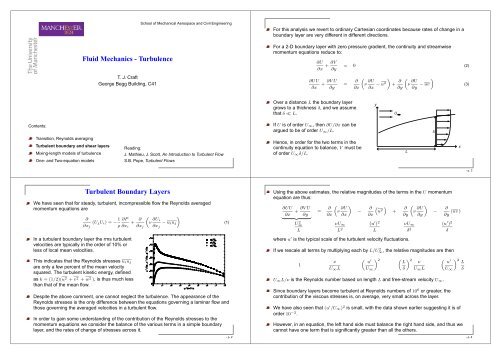
We have seen that for steady, turbulent, incompressible flow the Reynolds averaged<br />
momentum equations are<br />
∂<br />
(UjUi) = −<br />
∂xj<br />
1 ∂P<br />
ρ ∂xi<br />
In a turbulent boundary layer the rms turbulent<br />
velocities are typically in the order of 10% or<br />
less of local mean velocities.<br />
This indicates that the Reynolds stresses uiuj<br />
are only a few percent of the mean velocity<br />
squared. The turbulent kinetic energy, defined<br />
as k = (1/2)(u 2 + v 2 + w 2 ), is thus much less<br />
than that of the mean flow.<br />
+ ∂<br />
„<br />
ν<br />
∂xj<br />
∂Ui<br />
«<br />
− uiuj<br />
∂xj<br />
Despite the above comment, one cannot neglect the turbulence. The appearance of the<br />
Reynolds stresses is the only difference between the equations governing a laminar flow and<br />
those governing the averaged velocities in a turbulent flow.<br />
In order to gain some understanding of the contribution of the Reynolds stresses to the<br />
momentum equations we consider the balance of the various terms in a simple boundary<br />
layer, and the rates of change of stresses across it.<br />
(1)<br />
- p. 2<br />
For this analysis we revert to ordinary Cartesian coordinates because rates of change in a<br />
boundary layer are very different in different directions.<br />
For a 2-D boundary layer with zero pressure gradient, the continuity and streamwise<br />
momentum equations reduce to:<br />
∂UU<br />
∂x<br />
∂U ∂V<br />
+<br />
∂x ∂y<br />
+ ∂V U<br />
∂y<br />
Over a distance L the boundary layer<br />
grows to a thickness δ, and we assume<br />
that δ ≪ L.<br />
If U is of order U∞, then ∂U/∂x can be<br />
argued to be of order U∞/L.<br />
Hence, in order for the two terms in the<br />
continuity equation to balance, V must be<br />
of order U∞δ/L.<br />
= 0 (2)<br />
=<br />
„<br />
∂<br />
ν<br />
∂x<br />
∂U<br />
«<br />
− u2 +<br />
∂x ∂<br />
„<br />
ν<br />
∂y<br />
∂U<br />
«<br />
− uv<br />
∂y<br />
Using the above estimates, the relative magnitudes of the terms in the U momentum<br />
equation are thus:<br />
∂UU ∂V U<br />
+<br />
∂x ∂y<br />
| {z }<br />
U2 ∞<br />
L<br />
= ∂<br />
„<br />
ν<br />
∂x<br />
∂U<br />
«<br />
∂x<br />
νU∞<br />
L 2<br />
−<br />
y<br />
∂<br />
“<br />
u<br />
∂x<br />
2<br />
”<br />
(u ′ ) 2<br />
where u ′ is the typical scale of the turbulent velocity fluctuations.<br />
L<br />
U<br />
+<br />
L<br />
„<br />
∂<br />
ν<br />
∂y<br />
∂U<br />
«<br />
∂y<br />
νU∞<br />
δ 2<br />
δ<br />
−<br />
x<br />
∂<br />
(uv )<br />
∂y<br />
(u ′ ) 2<br />
If we rescale all terms by multiplying each by L/U 2 ∞, the relative magnitudes are then<br />
1<br />
ν<br />
U∞L<br />
„<br />
u ′ « 2<br />
U∞<br />
„ « 2<br />
L ν<br />
δ U∞L<br />
U∞L/ν is the Reynolds number based on length L and free-stream velocity U∞.<br />
δ<br />
„ u ′<br />
Since boundary layers become turbulent at Reynolds numbers of 10 6 or greater, the<br />
contribution of the viscous stresses is, on average, very small across the layer.<br />
We have also seen that (u ′ /U∞) 2 is small, with the data shown earlier suggesting it is of<br />
order 10 −2 .<br />
However, in an equation, the left hand side must balance the right hand side, and thus we<br />
cannot have one term that is significantly greater than all the others.<br />
U∞<br />
« 2 L<br />
δ<br />
(3)<br />
- p. 3<br />
- p. 4
We can conclude, therefore, that the most influential term on the right hand side is ∂uv /∂y.<br />
In order for this term to be of the correct magnitude, we also conclude that δ ≈ 10 −2 L.<br />
Notice that the streamwise gradient ∂u 2 /∂x is negligible in such a boundary layer, and it is<br />
only the turbulent shear stress uv which affects the mean velocity profile.<br />
However, the above analysis suggesting that viscous<br />
effects can be neglected cannot be correct across all<br />
of the boundary layer; in particular immediately<br />
adjacent to the wall, since the turbulent velocities must<br />
vanish at a rigid surface.<br />
As will be seen later, uv ∝ y 3 at the wall, so that in the<br />
immediate vicinity of the wall momentum must be<br />
diffused by viscosity rather than turbulent mixing.<br />
We thus get the picture of a near-wall<br />
viscosity-affected layer (often referred to as the<br />
viscous sublayer) where both viscous and turbulent<br />
effects may be important, and an outer, “fully turbulent”<br />
region, where direct viscous effects are negligible.<br />
The y Momentum Equation in a <strong>Boundary</strong> Layer<br />
The cross-stream momentum equation is<br />
∂UV ∂<br />
+ (V V )<br />
∂x ∂y<br />
| {z }<br />
U2 ∞δ<br />
L2 = − 1 ∂P<br />
ρ ∂y<br />
??<br />
„<br />
∂<br />
+ ν<br />
∂x<br />
∂V<br />
«<br />
∂x<br />
νU∞δ<br />
L 3<br />
The relative magnitudes of the terms are thus<br />
1 ??<br />
ν<br />
U∞L<br />
− ∂<br />
„<br />
∂<br />
(uv ) + ν<br />
∂x ∂y<br />
∂V<br />
«<br />
∂y<br />
„ u ′<br />
U∞<br />
(u ′ ) 2<br />
L<br />
« 2 L<br />
δ<br />
νU∞<br />
δL<br />
ν<br />
U∞L<br />
„ « 2<br />
L<br />
δ<br />
Since we have already concluded that (u ′ /U∞) 2 ≈ 10 −2 and δ/L ≈ 10 −2 , the term<br />
∂(uv )/∂x is O(1) and the final term in the equation has magnitude 10 2 .<br />
- p. 5<br />
− ∂<br />
“<br />
v<br />
∂y<br />
2<br />
”<br />
(u ′ ) 2<br />
δ<br />
„ u ′<br />
Thus, of all the terms whose relative magnitude is already known, the term ∂v 2 /∂y is the<br />
largest one.<br />
In an equation we cannot have one term much greater than all the others. Consequently, this<br />
last term must be balanced by the pressure gradient in the y direction:<br />
1 ∂P<br />
ρ ∂y<br />
≈ −∂v2<br />
∂y<br />
U∞<br />
« 2<br />
L<br />
δ<br />
- p. 6<br />
Integrating this equation across the boundary layer from some point within it to the free<br />
stream (where turbulence is assumed to be negligible), we get:<br />
P − P∞ = −ρv 2 or P = P∞ − ρv 2 (4)<br />
Thus, in a simple turbulent boundary layer we have P + ρv 2 being constant across the<br />
boundary layer.<br />
Note the contrast between this and the corresponding laminar situation where P is constant<br />
across the boundary layer.<br />
Total Shear Stress Across the <strong>Boundary</strong> Layer<br />
From the graph showing turbulent and molecular shear stress across the boundary layer one<br />
might guess that, across the near-wall layer, the sum of the two is almost constant.<br />
This result can be shown to follow from making certain assumptions about the boundary<br />
layer.<br />
Since streamwise gradients are small, the U-momentum equation in a zero pressure<br />
gradient boundary layer can be written<br />
∂(UU)<br />
∂x<br />
+ ∂(V U)<br />
∂y<br />
„<br />
∂<br />
= ν<br />
∂y<br />
∂U<br />
«<br />
− uv<br />
∂y<br />
If convective effects are also assumed to be small, then the above equation reduces to<br />
Integrating this gives<br />
0 = ∂<br />
„<br />
ν<br />
∂y<br />
∂U<br />
«<br />
− uv<br />
∂y<br />
ν ∂U<br />
− uv = Constant (7)<br />
∂y<br />
However, at the wall uv = 0 and ν∂U/∂y is simply the wall shear stress τw/ρ.<br />
- p. 7<br />
(5)<br />
(6)<br />
- p. 8
Hence we get the result that<br />
ν ∂U<br />
− uv = τw/ρ (8)<br />
∂y<br />
Since ν∂U/∂y is the viscous shear stress and −uv the turbulent shear stress, we thus<br />
deduce that the total shear stress is constant across the layer and equal to the wall shear<br />
stress.<br />
As can be seen from the graph, the<br />
assumptions do not hold right across the<br />
boundary layer, but are a reasonable<br />
approximation across the near-wall part of it.<br />
Mean Kinetic Energy Balance<br />
The mean kinetic energy K is defined as K = 0.5(U 2 + V 2 + W 2 ). In tensor notation this is<br />
usually written as K = 0.5U 2 i .<br />
The transport equation for K can be obtained by multiplying the Reynolds equation for Ui by<br />
the velocity Ui (note that this implies summation over the index i):<br />
» – "<br />
∂Ui ∂Ui<br />
Ui + Uj = Ui −<br />
∂t ∂xj<br />
1 ∂P<br />
ρ ∂xi<br />
The terms on the left hand side give<br />
∂Ui ∂ ` 2<br />
Ui = Ui /2<br />
∂t ∂t<br />
´ ≡ ∂K<br />
∂t<br />
The viscous terms can be written<br />
∂Ui<br />
and UiUj<br />
∂xj<br />
+ ν ∂2 Ui<br />
∂x 2 j<br />
∂<br />
= Uj<br />
∂xj<br />
− ∂uiuj<br />
#<br />
∂xj<br />
` 2<br />
Ui /2 ´ ∂K<br />
≡ Uj<br />
∂xj<br />
∂<br />
νUi<br />
2Ui ∂x2 =<br />
j<br />
∂<br />
„<br />
Ui ν<br />
∂xj<br />
∂Ui<br />
« „ « 2<br />
∂Ui<br />
− ν =<br />
∂xj ∂xj<br />
∂<br />
»<br />
ν<br />
∂xj<br />
∂ ` 2<br />
Ui /2<br />
∂xj<br />
´–<br />
„ « 2<br />
∂Ui<br />
− ν<br />
∂xj<br />
The terms involving the Reynolds stresses are<br />
∂uiuj<br />
−Ui =<br />
∂xj<br />
∂<br />
∂Ui<br />
(−Ui uiuj) + uiuj<br />
∂xj<br />
∂xj<br />
- p. 9<br />
- p. 10<br />
Thus, the K equation can be written as<br />
DK<br />
Dt<br />
∂<br />
= −1 (PUj) +<br />
ρ ∂xj<br />
∂<br />
„<br />
ν<br />
∂xj<br />
∂K<br />
«<br />
„ « 2<br />
∂Ui ∂Ui<br />
− Ui uiuj + uiuj − ν<br />
∂xj<br />
∂xj ∂xj<br />
Note that Dφ/Dt is used here, and elsewhere, to denote the total convective derivative:<br />
Dφ ∂φ<br />
≡<br />
Dt ∂t<br />
∂φ<br />
+ Uj<br />
∂xj<br />
≡ ∂φ ∂φ ∂φ ∂φ<br />
+ U + V + W<br />
∂t ∂x ∂y ∂z<br />
Note also that the convection velocities can be written either inside or outside the<br />
derivatives, since in an incompressible flow<br />
„ «<br />
∂Uφ ∂V φ ∂Wφ ∂φ ∂φ ∂φ ∂U ∂V ∂W<br />
+ + = U + V + W + φ + +<br />
∂x ∂y ∂z ∂x ∂y ∂z ∂x ∂y ∂z<br />
and the term in brackets is zero from continuity.<br />
The first term on the right hand side of equation (9) is the pressure work.<br />
The second term is diffusive in character, representing mixing due to viscosity and<br />
turbulence.<br />
The final term must be negative, and represents dissipation of mean kinetic energy by<br />
viscous action.<br />
The term involving Reynolds stresses and mean velocity gradients links the mean and<br />
turbulent kinetic energy equations, as will be seen later.<br />
Mean Kinetic Energy Budget in Plane Channel Flow<br />
Mean kinetic energy Mean kinetic energy budget<br />
(ut is the friction velocity (τw/ρ) 1/2 , and h the channel half-height)<br />
——: uv ∂U/∂y; – –: Pressure work;<br />
— —: Diffusion; - - -: Viscous dissipation<br />
(9)<br />
(10)<br />
(11)<br />
- p. 11<br />
- p. 12
<strong>Turbulent</strong> Kinetic Energy Balance<br />
The turbulent kinetic energy k is defined by k ≡ 0.5u 2 i ≡ 0.5(u2 + v 2 + w 2 ). To derive its<br />
transport equation, we can use<br />
Dk D<br />
“<br />
= u<br />
Dt Dt<br />
2 i /2<br />
”<br />
Dui<br />
= ui<br />
Dt<br />
To proceed further, we need a transport equation for the fluctuating velocity ui. This can be<br />
obtained by subtracting the Reynolds-averaged momentum equation from the Navier Stokes<br />
equation:<br />
Dui<br />
Dt = D e Ui DUi<br />
−<br />
Dt Dt<br />
The derivation is left as an exercise, but the result is:<br />
∂ui<br />
∂t<br />
∂ui<br />
+ Uj<br />
∂xj<br />
= − 1 ∂p<br />
ρ ∂xi<br />
(12)<br />
∂Ui<br />
− uj + ν<br />
∂xj<br />
∂2ui ∂x2 −<br />
j<br />
∂<br />
(uiuj − uiuj) (13)<br />
∂xj<br />
Multiplying this equation by the fluctuating velocity ui (note, again, the implied summation<br />
over the index i), and averaging, we can arrive at:<br />
∂k<br />
∂t<br />
∂k ∂Ui<br />
+ Uj = −uiuj<br />
∂xj ∂xj<br />
− ν ∂ui ∂ui<br />
−<br />
∂xj ∂xj<br />
∂<br />
„<br />
u<br />
∂xi<br />
2 jui/2 + uip/ρ − ν ∂k<br />
«<br />
∂xi<br />
The second term on the right hand side of equation (14) represents the dissipation of<br />
turbulent kinetic energy by viscosity at the smallest scales.<br />
The last term represents diffusion, as a result of viscous and turbulent mixing.<br />
The term −uiuj ∂Ui/∂xj must therefore represent the generation of turbulent kinetic energy.<br />
It appears in both kinetic energy equations, and can thus be interpreted as the rate at which<br />
kinetic energy is lost from the mean flow and transferred to the turbulent eddies.<br />
The term −uiuj ∂Ui/∂xj is often denoted by Pk and called the production, or generation,<br />
rate of k.<br />
In most circumstances Pk is positive, representing a transfer of kinetic energy from the mean<br />
flow to the turbulence. However, there are flow conditions under which Pk can be locally<br />
negative in certain regions.<br />
(14)<br />
- p. 13<br />
- p. 14<br />
<strong>Turbulent</strong> Kinetic Energy Budget in Plane Channel Flow<br />
<strong>Turbulent</strong> kinetic energy <strong>Turbulent</strong> kinetic energy budget<br />
1/2<br />
——: −uv ∂U/∂y;<br />
– –: Diffusion;<br />
- - -: Dissipation<br />
max<br />
max<br />
Energy Flow Processes Near a Wall<br />
If we make the usual boundary layer or thin shear flow approximation<br />
that U(y) is the only non-zero mean velocity component, then the<br />
mean kinetic energy equation becomes:<br />
DK<br />
Dt = ν ∂2K ∂y2 „ « 2<br />
∂U<br />
− ν −<br />
∂y<br />
| {z } | {z }<br />
Term 1 Term 2<br />
∂<br />
∂x (PU/ρ) + uv<br />
| {z }<br />
Term 3<br />
∂U<br />
−<br />
∂y<br />
| {z }<br />
Term 4<br />
∂<br />
(Uuv )<br />
∂y<br />
| {z }<br />
Term 5<br />
If we consider a simple turbulent near-wall flow, where the streamwise pressure gradient is<br />
small, the convective rate of change of K is generally found to be much smaller than the<br />
individual source and sink terms on the right.<br />
The K equation is then approximated by<br />
(15)<br />
0 = ν ∂2K ∂y2 „ « 2<br />
∂U<br />
− ν + uv<br />
∂y<br />
| {z } | {z }<br />
Term 1 Term 2<br />
∂U<br />
−<br />
∂y<br />
| {z }<br />
Term 4<br />
∂<br />
(Uuv )<br />
∂y<br />
| {z }<br />
Term 5<br />
y<br />
U(y)<br />
- p. 15<br />
(16)<br />
- p. 16
As seen earlier, in the near-wall layer of a zero pressure gradient turbulent boundary layer<br />
we get a constant total shear stress:<br />
ν ∂U<br />
− uv = Const = τw/ρ (17)<br />
∂y<br />
This result showed that the sum of the turbulent shear stress (-uv ) and molecular shear<br />
stress (ν∂U/∂y) is constant across the boundary layer (and equal in magnitude to the wall<br />
shear stress).<br />
As seen in the earlier graphs, very close to the wall the turbulent shear stress becomes<br />
small in magnitude and viscous effects must therefore grow. The viscous terms in the K<br />
equation will therefore dominate in this region, and Terms 1 and 2 in equation (16) must<br />
therefore be in balance very close to the wall.<br />
Beyond this viscous sublayer, however, the effects of viscosity on the mean flow are<br />
negligible. There must then be a balance between terms 4 and 5.<br />
In this outer region (the fully-turbulent region), we will see later that the mean velocity U<br />
varies as log(y), so ∂U/∂y ∝ y −1 .<br />
When viscous effects are negligible, equation (17) shows that the turbulent shear stress<br />
uv ≈ −τw/ρ. The rate of loss of mean kinetic energy to turbulence (Term 4) is thus<br />
proportional to y −1 in this outer region, so decreases with distance from the wall.<br />
However, uv ∂U/∂y is zero at the wall (as uv is zero there). Since, as noted above, it<br />
decreases in magnitude across the ‘log-layer’ as y increases, it must reach a maximum in<br />
magnitude at some point between the wall and the log-layer.<br />
Thus the rate of transforming mean kinetic energy into turbulent kinetic energy must be<br />
greatest at some point closer to the wall than the log-layer.<br />
We can examine where exactly in the boundary layer this energy transformation rate is<br />
greatest.<br />
Since the energy transfer rate is given by −uv ∂U/∂y, the maximum transfer rate occurs<br />
where<br />
„<br />
∂<br />
uv<br />
∂y<br />
∂U<br />
«<br />
= 0<br />
∂y<br />
(18)<br />
This equation can be expanded to give<br />
∂uv<br />
∂y<br />
- p. 17<br />
∂U<br />
∂y + uv ∂2U = 0 (19)<br />
∂y2 Eliminating uv from the first term, with the help of equation (17), we obtain<br />
∂U<br />
∂y<br />
„<br />
∂<br />
ν<br />
∂y<br />
∂U<br />
«<br />
− τw/ρ<br />
∂y<br />
+ uv ∂2U = 0<br />
∂y2 - p. 18<br />
Since ν and τw/ρ are constants:<br />
Finally, on cancelling ∂ 2 U/∂y 2 :<br />
ν ∂U<br />
∂y<br />
= −uv<br />
ν ∂U ∂<br />
∂y<br />
2U ∂y2 = −uv ∂2U ∂y2 Hence the rate of loss of mean kinetic energy to<br />
turbulence is greatest where the viscous stress<br />
equals the turbulent shear stress.<br />
The generation rate of k thus takes its maximum not<br />
in the ‘fully turbulent’ region, but in the<br />
viscosity-affected region of the boundary layer.<br />
It is also easy to show that at this point the viscous<br />
dissipation of mean kinetic energy equals the loss to<br />
turbulence.<br />
As seen earlier, there are significant<br />
differences between the levels of the stress<br />
components away from the wall. In a<br />
boundary layer (or shear flow) with mean<br />
velocity U(y), one generally finds<br />
u 2 > w 2 > v 2 .<br />
Energy Loss<br />
2<br />
x ν(τ w/ρ)<br />
1.0<br />
0.25<br />
Laminar<br />
sublayer<br />
τ /ρ<br />
w<br />
Near-Wall Reynolds Stresses<br />
The question we address here is how do the<br />
stresses behave very close to the wall, as they<br />
approach zero.<br />
Viscous sublayer<br />
Viscous dissipation<br />
Buffer layer<br />
Loss to turbulence<br />
y<br />
<strong>Turbulent</strong><br />
shear stress<br />
Viscous<br />
shear stress<br />
To examine the near-wall behaviour of the stresses, we can express the near-wall velocities<br />
as Taylor series expansions in powers of y (the wall-normal distance):<br />
u = a1y + b1y 2 + c1y 3 + . . .<br />
v = a2y + b2y 2 + c2y 3 + . . .<br />
w = a3y + b3y 2 + c3y 3 + . . .<br />
where the a’s, b’s, c’s etc. are functions of x, z and t.<br />
The above expansions do ensure that the velocities vanish at the wall, but they must also<br />
satisfy continuity (∂u/∂x + ∂v/∂y + ∂w/∂z = 0).<br />
y<br />
- p. 19<br />
- p. 20
Substituting the expansions for the velocities into the continuity equation:<br />
y ∂a1/∂x + y 2 ∂b1/∂x + . . .<br />
+ a2 + 2 y b2 + 3 y 2 c2 + . . .<br />
Considering the O(1) terms leads to a2 = 0.<br />
Hence close to the wall the velocities behave<br />
as u ∝ y, w ∝ y, but v ∝ y 2 .<br />
The Reynolds stresses thus behave as<br />
u 2 ∝ y 2 , v 2 ∝ y 4 , w 2 ∝ y 2 and uv ∝ y 3 for<br />
small y.<br />
+ y ∂a3/∂z + y 2 ∂b3/∂z + . . . = 0<br />
- p. 21