6110 Hand-Held Computer User's Guide - Intermec
6110 Hand-Held Computer User's Guide - Intermec
6110 Hand-Held Computer User's Guide - Intermec

Create successful ePaper yourself
Turn your PDF publications into a flip-book with our unique Google optimized e-Paper software.
<strong>6110</strong> <strong>Hand</strong>-<strong>Held</strong> <strong>Computer</strong><br />
USER’S GUIDE<br />
" " " " " " " " " " " " " " " " " " " " " " " " " " " "<br />
PN: 961-028-102<br />
Revision F<br />
August 2000
" NOTICE This publication contains information proprietary to <strong>Intermec</strong> Technologies Corporation.<br />
It is being supplied to you with the express understanding that the information<br />
contained herein is for the benefit of the contracting party only, and may not<br />
be copied, distributed, or displayed to third parties without the express written<br />
consent of <strong>Intermec</strong> Technologies Corporation, and shall be returned to <strong>Intermec</strong><br />
Technologies Corporation upon written request. If a purchase, license, or nondisclosure<br />
agreement has been executed, the terms of that agreement shall govern this<br />
document.<br />
This publication is furnished for information only, and the information in it is<br />
subject to change without notice. Although every effort has been made to provide<br />
complete and accurate information, <strong>Intermec</strong> Technologies Corporation assumes no<br />
responsibility or liability for any errors or inaccuracies that may appear in this<br />
document.<br />
Disclaimer of Warranties. The sample source code included in this document is<br />
presented for reference only. The code does not necessarily represent complete,<br />
tested programs. The code is provided “AS IS WITH ALL FAULTS.” ALL<br />
WARRANTIES ARE EXPRESSLY DISCLAIMED, INCLUDING THE<br />
IMPLIED WARRANTIES OF MERCHANTABILITY AND FITNESS FOR A<br />
PARTICULAR PURPOSE.<br />
We welcome your comments concerning this publication. Although every effort has<br />
been made to keep it free of errors, some may occur. When reporting a specific<br />
problem, please describe it briefly and include the book title and part number, as<br />
well as the paragraph or figure number and the page number.<br />
Send your comments to:<br />
<strong>Intermec</strong> Technologies Corporation<br />
Publications Department<br />
550 Second Street SE<br />
Cedar Rapids, IA 52401<br />
INTERMEC, NORAND, PEN*KEY, PEN*VIEW, ROUTE-COMMANDER, and<br />
BEVERAGE ROUTEBOOK are registered trademarks and NOR*WARE and<br />
RAPIDREP are trademarks of <strong>Intermec</strong> Technologies Corporation.<br />
© 1998 <strong>Intermec</strong> Technologies Corporation. All rights reserved.<br />
Acknowledgments<br />
Alexander is a registered trademark of Alexander Manufacturing Co.<br />
Ethernet is a trademark of Xerox Corporation.<br />
Microclean II is a registered trademark of Foresight International.<br />
Microsoft, MS, and MS-DOS, and Windows, are registered trademarks and Visual<br />
Basic for Windows, and Windows for Pen are trademarks of Microsoft Corporation.<br />
SanDisk is a trademark of SanDisk Corporation
CONTENTS<br />
" " " " " " " " " " " " " " " " " " " " " " " " " " " "<br />
SECTION 1<br />
General Information<br />
About This User’s <strong>Guide</strong> . . . . . . . . . . . . . . . . . . . . . . . . . . . . . 1-1<br />
<strong>Hand</strong>-<strong>Held</strong> <strong>Computer</strong> Description . . . . . . . . . . . . . . . . . . . . . 1-2<br />
<strong>Hand</strong>-<strong>Held</strong> <strong>Computer</strong> Keyboard . . . . . . . . . . . . . . . . . . . 1-4<br />
<strong>Hand</strong>-<strong>Held</strong> <strong>Computer</strong> . . . . . . . . . . . . . . . . . . . . . . . . . . . . . 1-4<br />
Display . . . . . . . . . . . . . . . . . . . . . . . . . . . . . . . . . . . . . . . . . . 1-5<br />
Battery . . . . . . . . . . . . . . . . . . . . . . . . . . . . . . . . . . . . . . . . . . 1-5<br />
Memory . . . . . . . . . . . . . . . . . . . . . . . . . . . . . . . . . . . . . . . . . 1-6<br />
[Gold] (Shift) Key . . . . . . . . . . . . . . . . . . . . . . . . . . . . . . . . 1-10<br />
[I/O] Suspend and Resume Key . . . . . . . . . . . . . . . . . . . . 1-10<br />
Serial Ports . . . . . . . . . . . . . . . . . . . . . . . . . . . . . . . . . . . . . . 1-11<br />
Resetting . . . . . . . . . . . . . . . . . . . . . . . . . . . . . . . . . . . . . . . . 1-11<br />
Options and Accessories . . . . . . . . . . . . . . . . . . . . . . . . . . . . . . 1-11<br />
Radio Card . . . . . . . . . . . . . . . . . . . . . . . . . . . . . . . . . . . . . . 1-11<br />
Integrated Scanner Pod . . . . . . . . . . . . . . . . . . . . . . . . . . . 1-12<br />
Port Replicator . . . . . . . . . . . . . . . . . . . . . . . . . . . . . . . . . . . 1-13<br />
Magnetic Stripe Reader . . . . . . . . . . . . . . . . . . . . . . . . . . . 1-14<br />
Serial Pod . . . . . . . . . . . . . . . . . . . . . . . . . . . . . . . . . . . . . . .<br />
Global Systems for Mobile Communication (GSM)<br />
1-15<br />
with Subscriber Identity Module (SIM) . . . . . . . . . 1-16<br />
<strong>Hand</strong>-<strong>Held</strong> <strong>Computer</strong> Specifications . . . . . . . . . . . . . . . . . . .<br />
1-17<br />
<strong>6110</strong> <strong>Hand</strong>-<strong>Held</strong> <strong>Computer</strong> User’s <strong>Guide</strong> i
CONTENTS<br />
SECTION 2<br />
Operation<br />
Introduction . . . . . . . . . . . . . . . . . . . . . . . . . . . . . . . . . . . . . . . . . 2-1<br />
Getting Started . . . . . . . . . . . . . . . . . . . . . . . . . . . . . . . . . . . . . . 2-1<br />
Rechargeable Battery Label . . . . . . . . . . . . . . . . . . . . . . . . . . 2-2<br />
Installing the Main Battery . . . . . . . . . . . . . . . . . . . . . . . . . . . 2-3<br />
Charging The Batteries . . . . . . . . . . . . . . . . . . . . . . . . . . . . . . 2-4<br />
In Your <strong>Hand</strong>-<strong>Held</strong> <strong>Computer</strong> . . . . . . . . . . . . . . . . . . . . . 2-4<br />
In External Source . . . . . . . . . . . . . . . . . . . . . . . . . . . . . . . 2-6<br />
Removing the Main Battery . . . . . . . . . . . . . . . . . . . . . . . . . . 2-8<br />
Measuring Battery Pack Capacity . . . . . . . . . . . . . . . . . . . . . 2-9<br />
Backup Battery . . . . . . . . . . . . . . . . . . . . . . . . . . . . . . . . . . . . . . 2-10<br />
Backup Battery Life . . . . . . . . . . . . . . . . . . . . . . . . . . . . . . . . . 2-10<br />
Using PC Cards to Load Your Programs . . . . . . . . . . . . . . . 2-11<br />
Drives . . . . . . . . . . . . . . . . . . . . . . . . . . . . . . . . . . . . . . . . . . 2-11<br />
Booting . . . . . . . . . . . . . . . . . . . . . . . . . . . . . . . . . . . . . . . . . 2-11<br />
BIOS Update . . . . . . . . . . . . . . . . . . . . . . . . . . . . . . . . . . . . 2-11<br />
Installing PC Cards . . . . . . . . . . . . . . . . . . . . . . . . . . . . . . . . . . 2-11<br />
Removing PC Cards . . . . . . . . . . . . . . . . . . . . . . . . . . . . . . . . . . 2-13<br />
Installing a Modem Card . . . . . . . . . . . . . . . . . . . . . . . . . . . . . 2-14<br />
Using the Magnetic Stripe Reader (MSR) . . . . . . . . . . . . . . 2-16<br />
Installing the Subscriber Identity Module (SIM) . . . . . . . . 2-17<br />
SECTION 3<br />
Routine Care and Maintenance<br />
Introduction . . . . . . . . . . . . . . . . . . . . . . . . . . . . . . . . . . . . . . . . . 3-1<br />
Low Battery Indication . . . . . . . . . . . . . . . . . . . . . . . . . . . . . . . 3-1<br />
Cleaning Your <strong>Hand</strong>-<strong>Held</strong> <strong>Computer</strong> . . . . . . . . . . . . . . . . . . 3-2<br />
Case and Display . . . . . . . . . . . . . . . . . . . . . . . . . . . . . . . . 3-2<br />
Docking Connectors . . . . . . . . . . . . . . . . . . . . . . . . . . . . . . 3-2<br />
SECTION 4<br />
Troubleshooting<br />
Introduction . . . . . . . . . . . . . . . . . . . . . . . . . . . . . . . . . . . . . . . . . 4-1<br />
Troubleshooting Chart . . . . . . . . . . . . . . . . . . . . . . . . . . . . . . . 4-2<br />
Repair Service . . . . . . . . . . . . . . . . . . . . . . . . . . . . . . . . . . . . . . .<br />
4-6<br />
ii <strong>6110</strong> <strong>Hand</strong>-<strong>Held</strong> <strong>Computer</strong> User’s <strong>Guide</strong>
APPENDIX A<br />
Connector Pin-Outs<br />
CONTENTS<br />
8-Pin Docking Connector . . . . . . . . . . . . . . . . . . . . . . . . . . . . . A-2<br />
RJ-45 Phone Jack Pin-Outs . . . . . . . . . . . . . . . . . . . . . . . . . . . A-3<br />
APPENDIX B<br />
PEN*KEY Utilities Program<br />
Entry Point . . . . . . . . . . . . . . . . . . . . . . . . . . . . . . . . . . . . . . . . . B-1<br />
Pop-Up Menus . . . . . . . . . . . . . . . . . . . . . . . . . . . . . . . . . . . . . . B-1<br />
Drop-Down Lists . . . . . . . . . . . . . . . . . . . . . . . . . . . . . . . . . . . . B-2<br />
Alphanumeric Fields . . . . . . . . . . . . . . . . . . . . . . . . . . . . . . . . . B-3<br />
Title Screen . . . . . . . . . . . . . . . . . . . . . . . . . . . . . . . . . . . . . . . . . B-4<br />
Language Selection . . . . . . . . . . . . . . . . . . . . . . . . . . . . . . . . . . B-5<br />
Communications Menu . . . . . . . . . . . . . . . . . . . . . . . . . . . . . . . B-6<br />
Option 1 BEGIN COMM SESSION . . . . . . . . . . . . . . . . B-7<br />
Option 2 COMM SETTING . . . . . . . . . . . . . . . . . . . . . . . B-17<br />
Option 3 UNIT ID . . . . . . . . . . . . . . . . . . . . . . . . . . . . . . . . B-21<br />
Option 4 NETWORK PARAMETERS . . . . . . . . . . . . . . B-21<br />
Option 4 MODEM PARAMETERS . . . . . . . . . . . . . . . . . B-23<br />
Option 5 NETWORK INTERFACE . . . . . . . . . . . . . . . . B-27<br />
Option 5 PHONE NUMBER . . . . . . . . . . . . . . . . . . . . . . B-28<br />
Option 9 ADVANCED UTILITIES . . . . . . . . . . . . . . . . . B-29<br />
FIGURES<br />
Figure 1-1 Front View . . . . . . . . . . . . . . . . . . . . . . . . . . . . . . . . 1-3<br />
Figure 1-2 Back View . . . . . . . . . . . . . . . . . . . . . . . . . . . . . . . . 1-3<br />
Figure 1-3 16-Key Keyboard . . . . . . . . . . . . . . . . . . . . . . . . . . 1-4<br />
Figure 1-4 PC Card Slots . . . . . . . . . . . . . . . . . . . . . . . . . . . . 1-8<br />
Figure 1-5 PC Card Slots . . . . . . . . . . . . . . . . . . . . . . . . . . . . 1-9<br />
Figure 1-6 Integrated Scanner Pod . . . . . . . . . . . . . . . . . . . . 1-12<br />
Figure 1-7 Port Replicator . . . . . . . . . . . . . . . . . . . . . . . . . . . 1-13<br />
Figure 1-8 Magnetic Stripe Reader . . . . . . . . . . . . . . . . . . . . 1-14<br />
Figure 1-9 Serial Pod . . . . . . . . . . . . . . . . . . . . . . . . . . . . . . . . 1-15<br />
Figure 1-10 GSM with SIM card . . . . . . . . . . . . . . . . . . . . . . 1-16<br />
Figure 2-1 Installing Main Battery Pack . . . . . . . . . . . . . . . 2-3<br />
Figure 2-2 Power Status LED . . . . . . . . . . . . . . . . . . . . . . . . . 2-5<br />
Figure 2-3 Multipack Charger . . . . . . . . . . . . . . . . . . . . . . . .<br />
2-6<br />
<strong>6110</strong> <strong>Hand</strong>-<strong>Held</strong> <strong>Computer</strong> User’s <strong>Guide</strong> iii
CONTENTS<br />
Figure 2-4 Single Pack Charger . . . . . . . . . . . . . . . . . . . . . . . 2-7<br />
Figure 2-5 SPAN Charger . . . . . . . . . . . . . . . . . . . . . . . . . . . . 2-7<br />
Figure 2-6 Removing the Main Battery Pack . . . . . . . . . . . 2-8<br />
Figure 2-7 Main Battery Pack Underside View<br />
Showing Contacts . . . . . . . . . . . . . . . . . . . . . . . . . . . . . . . . 2-9<br />
Figure 2-8 Accessing the PC Card Slots . . . . . . . . . . . . . . . . 2-12<br />
Figure 2-9 Individual PC Card Slot Ejector Buttons . . . . . 2-13<br />
Figure 2-10 Installing Modem Card . . . . . . . . . . . . . . . . . . 2-14<br />
Figure 2-11 Installing Modem Cable . . . . . . . . . . . . . . . . . . 2-15<br />
Figure 2-12 Using the Magnetic Stripe Reader . . . . . . . . . 2-16<br />
Figure 2-13 Removing SIM Socket Cover . . . . . . . . . . . . . . 2-17<br />
Figure 2-14 Installing SIM . . . . . . . . . . . . . . . . . . . . . . . . . . . 2-18<br />
Figure A-1 Docking Connector Pin-Outs . . . . . . . . . . . . . . . A-2<br />
Figure A-2 Phone Jack Pin-Outs . . . . . . . . . . . . . . . . . . . . . . A-3<br />
TABLES<br />
Table 4-1 Basic Troubleshooting . . . . . . . . . . . . . . . . . . . . . . . 4-2<br />
GLOSSARY<br />
INDEX<br />
iv <strong>6110</strong> <strong>Hand</strong>-<strong>Held</strong> <strong>Computer</strong> User’s <strong>Guide</strong>
Section 1<br />
General Information<br />
" " " " " " " " " " " " " " " " " " " " " " " " " " " "<br />
About This User’s <strong>Guide</strong><br />
Section 1<br />
Contains general information about the components of your<br />
<strong>Intermec</strong> <strong>6110</strong> <strong>Hand</strong>-<strong>Held</strong> <strong>Computer</strong>. This includes telling<br />
you how the user guide is organized, a summary of the sections,<br />
and the specifications for your hand-held computer.<br />
Section 2<br />
Tells you how to prepare for using your computer.<br />
Section 3<br />
Contains routine maintenance information for your computer.<br />
Routine maintenance includes recharging the main battery<br />
pack, and cleaning the computer.<br />
Section 4<br />
Steps you through some procedures to use when troubleshooting<br />
your computer. This section does not contain all<br />
troubleshooting that can be done by an authorized Customer<br />
Support Specialist, but does contain information to aid<br />
you in determining the level of assistance you may need.<br />
<strong>6110</strong> <strong>Hand</strong>-<strong>Held</strong> <strong>Computer</strong> User’s <strong>Guide</strong> 1-1
General Information<br />
Appendix A<br />
1-2 <strong>6110</strong> <strong>Hand</strong>-<strong>Held</strong> <strong>Computer</strong> User’s <strong>Guide</strong><br />
SECTION 1<br />
Contains the pin-outs for the external connectors of your<br />
hand-held computer. This section is not usually needed for<br />
day-to-day tasks but more to provide technical assistance<br />
for interfacing with other manufacturer’s products.<br />
Appendix B<br />
Contains the Utilities Program screens. This is system level<br />
information for your system administration people when<br />
defining and setting parameters to support your application.<br />
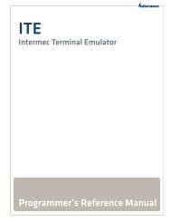
<strong>Hand</strong>-<strong>Held</strong> <strong>Computer</strong> Description<br />
<strong>Hand</strong>-held computers are used in the mobile systems marketplace<br />
to perform a wide variety of tasks. This hand-held<br />
computer provides features and benefits that include:<br />
" Fast data processing<br />
" Large data and program storage<br />
" Touch screen display<br />
" Signature capture<br />
Additionally, your computer has the ability to use:<br />
" PC (Personal <strong>Computer</strong>) cards<br />
" Internal modem with PC card size and format<br />
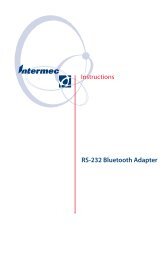
The following descriptions will familiarize you with the<br />
name, function, and locations of the main computer components.<br />
Figure 1-1, and Figure 1-2, on pages 1-3, show you<br />
the location for your hand-held computer key components.
SECTION 1 General Information<br />
DC Power Jack<br />
Infrared (IrDA)<br />
Lens<br />
Speaker<br />
Slot<br />
Figure 1-1<br />
Front View<br />
Figure 1-2<br />
Back View<br />
Touch Screen<br />
Stylus<br />
Keypad<br />
Optional External<br />
RF Jack<br />
Docking Connector<br />
Battery Pack<br />
Battery Pack Latch<br />
Magnetic<br />
Strip Reader<br />
(optional)<br />
PC Card Door<br />
RJ-45 Jack (optional)<br />
External Antenna Jack or<br />
DEX Connector (optional)<br />
<strong>6110</strong> <strong>Hand</strong>-<strong>Held</strong> <strong>Computer</strong> User’s <strong>Guide</strong> 1-3
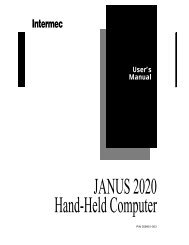
General Information<br />
Power Status LED<br />
Scanning Status LED<br />
I/O (Suspend/Resume) Key<br />
Tab Key<br />
BkSp (Back Space) Key<br />
GOLD (Shift Key)<br />
<strong>Hand</strong>-<strong>Held</strong> <strong>Computer</strong> Keyboard<br />
1-4 <strong>6110</strong> <strong>Hand</strong>-<strong>Held</strong> <strong>Computer</strong> User’s <strong>Guide</strong><br />
SECTION 1<br />
The hand-held computer provides a 16 key keyboard. All<br />
keys with the exception of the I/O key are programmable for<br />
individual functions. Figure 1-3 details the basic keyboard<br />
layout.<br />
ESC (Escape) Key<br />
Figure 1-3<br />
16-Key Keyboard<br />
Numeric Keys<br />
ENTER Key
SECTION 1 General Information<br />
Display<br />
This hand-held computer offers an easy to read Liquid<br />
Crystal Display (LCD) with touch screen. The display<br />
shows status messages, keyed-in entries, customer or product<br />
lists, calculations, and prompts for responses. The touch<br />
screen can be used with a stylus, or your finger to choose<br />
functions, record signatures, or enter data.<br />
Adjusting the contrast setting for the display is done by<br />
pressing the gold Shift key and tap either the 1 (increase) or<br />
2 (decrease) key until you achieve the desired level. Of<br />
course, this will depend on if these keys have not been programmed<br />
for other functions.<br />
Backlight<br />
Your hand-held computer display and keyboard comes<br />
equipped with a backlight. Backlighting provides a great<br />
benefit in dark conditions.<br />
Backlighting does, however, reduce battery life, therefore,<br />
turn off the backlight when done using.<br />
To turn the backlight on, press the gold Shift key and the 3<br />
key. To turn the backlight off, press gold Shift and the 3 key<br />
again. The amount of time the backlight stays on before<br />
shutting itself off is set and controlled through the Configuration<br />
Program.<br />
Battery<br />
" NOTE: It is important to charge your hand-held computer for at least 14<br />
hours before you use it the first time. This ensures that both the<br />
backup battery and the main battery pack are fully charged.<br />
This hand-held computer uses a 1500 mA hour lithium ion<br />
rechargeable main battery pack. Your hand-held computer<br />
can check battery capacity by various methods. One, the<br />
battery pack has four LEDs that will display remaining ca-<br />
<strong>6110</strong> <strong>Hand</strong>-<strong>Held</strong> <strong>Computer</strong> User’s <strong>Guide</strong> 1-5
General Information<br />
1-6 <strong>6110</strong> <strong>Hand</strong>-<strong>Held</strong> <strong>Computer</strong> User’s <strong>Guide</strong><br />
SECTION 1<br />
pacity when two of the contacts are touched at the same<br />
time. More on this in Section 2 on page 2-9. A second method<br />
is to use a software fuel gauge based on the APM 1.1<br />
specification.<br />
If your hand-held computer goes into a shutdown mode because<br />
of low battery condition, data is protected by the<br />
backup battery. Your computer contains two 100 mA hour<br />
vanadium lithium backup batteries. The backup battery<br />
charges itself from the main pack or a charging source so it<br />
is constantly ready to take over data protection.<br />
This user’s guide will occasionally use the term “cycles”<br />
when presenting rechargeable battery instructions. Cycles,<br />
are the number of times the rechargeable battery pack can<br />
be charged and discharged during the life of battery. The<br />
Lithium Ion rechargeable battery design, used in the main<br />
pack, should give you approximately 500 cycles of use.<br />
There are no guarantees on this number because it depends<br />
greatly on how the battery pack is used and cared for.<br />
Memory<br />
Three types of memory are available with this computer:<br />
" Main Memory DRAM<br />
" Flash ROM<br />
" PC Cards<br />
Main Memory<br />
Standard main memory DRAM configuration is 8 megabytes<br />
(MB), this can be extended to 16, or 32 MBs. Main<br />
memory was ordered at the time your unit was purchased.<br />
You are able to upgrade to a larger memory size by having a<br />
new memory board installed at your Customer Support<br />
Center.<br />
The main memory is protected by the backup battery during<br />
low main battery conditions or when the main battery<br />
pack is removed.
SECTION 1 General Information<br />
Flash ROM<br />
Flash ROM stores the BIOS and BIOS extensions for your<br />
hand-held computer.<br />
PC Cards<br />
Different brands of PC cards can be used in your hand-held<br />
computer. Memory cards are available in a variety of sizes<br />
and types. Check with your Sales Representative or System<br />
Engineer for specific options.<br />
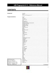
Your computer is equipped with three PC card slots. These<br />
slots can be used with memory cards for storage of data,<br />
much like a floppy disk drive on a PC. These slots can also<br />
be used for modems, radios, hard drives, and other options<br />
as they become available.<br />
Two of the PC card slots are version 2.0 Type II and the<br />
other slot is an ATA card slot. Type III cards can be<br />
installed but you sacrifice slot space. The ATA and two PC<br />
slots have card guides, but the empty bay on top does not.<br />
There is no blockage between any of the slots, so any pair of<br />
Type II bays can accommodate a Type III card.<br />
EXAMPLE: A Type III ATA hard drive card can be installed in the ATA slot, but it<br />
takes up the PC slot B bay space. A Type III PC card installed in slot<br />
B takes up slot B and A; and a Type III PC card installed in slot A<br />
takes up slot A and the empty bay.<br />
<strong>6110</strong> <strong>Hand</strong>-<strong>Held</strong> <strong>Computer</strong> User’s <strong>Guide</strong> 1-7
General Information<br />
1-8 <strong>6110</strong> <strong>Hand</strong>-<strong>Held</strong> <strong>Computer</strong> User’s <strong>Guide</strong><br />
Figure 1-4<br />
PC Card Slots<br />
Empty Bay<br />
Slot A (typically<br />
used for a radio<br />
card)<br />
SECTION 1<br />
Slot B (typically<br />
used for a modem<br />
card<br />
Slot C (typically<br />
used for a hard<br />
drive card or a<br />
SanDisk flash<br />
ATA card)
SECTION 1 General Information<br />
Slot A<br />
Slot B<br />
Slot C<br />
Flashdisk or hard drive card<br />
Slot C<br />
Modem card<br />
Slot B<br />
Figure 1-5<br />
PC Card Slots<br />
Radio card<br />
Slot A<br />
When a card is installed, the top label of the card faces upward<br />
(per the orientation shown in Figure 1-5). Slot C (ATA<br />
slot) must always have a mass storage device to serve as<br />
the system disk (C:). This can be a SanDisk flash memory<br />
card or a rotating hard disk drive. The system will not operate<br />
without this disk present.<br />
<strong>6110</strong> <strong>Hand</strong>-<strong>Held</strong> <strong>Computer</strong> User’s <strong>Guide</strong> 1-9
General Information<br />
1-10 <strong>6110</strong> <strong>Hand</strong>-<strong>Held</strong> <strong>Computer</strong> User’s <strong>Guide</strong><br />
SECTION 1<br />
Slots A and B are true PC card slots, and can accommodate<br />
a variety of pc cards such as modems, radios, or additional<br />
mass storage.<br />
A special factory installed option involves a serial interface<br />
radio card (example: Motorola Series 500 Radio) for use in<br />
slot A. This type of card does not have PC interface, therefore,<br />
it cannot be inserted all the way into the connector at<br />
the back of the bay. A special bracket holds the card in<br />
place, and the serial interface is attached via a flex cable.<br />
" NOTE: Section 2 page 2-11 shows you how to install the PC cards.<br />
[Gold] (Shift) Key<br />
Hold down and press desired gold (shifted) key functions.<br />
Continue to hold down the [GOLD] key for each shifted key<br />
stroke you wish to make.<br />
[I/O] Suspend and Resume Key<br />
In order to conserve power your hand-held computer may<br />
automatically suspend when there has been no activity for<br />
a set period of time. This time is determined by the configuration<br />
program.<br />
To force a suspend, press the key defined as the suspend<br />
key and hold the key down for three seconds. To resume operation,<br />
press the [I/O] key. Additionally, pressing the release<br />
button on the battery pack door forces a suspend. This<br />
protects against losing data when removing the battery<br />
pack.
SECTION 1 General Information<br />
Serial Ports<br />
" Optional DB9 pod<br />
" Optional RS-232 subset through the DEX connector.<br />
" Optional RS-232 through RJ-45 jack in top of<br />
computer.<br />
" IrDA partial serial port through IR lens.<br />
Resetting<br />
In the rare event that your hand-held computer fails to respond<br />
to your input, it may be necessary to “reset.” To reset<br />
press the Gold (shift), Ctrl, Alt keys at the same time, hold<br />
the keys down for three seconds, and your computer will<br />
reboot.<br />
Options and Accessories<br />
Radio Card<br />
Your hand-held computer can be ordered with a radio card.<br />
Using a radio card allows you to operate in a mobile environment<br />
and have real-time interaction with a host computer.<br />
The radio card slides into either PC card slot A or B (see<br />
page 2-11 for installation and location detail).<br />
<strong>6110</strong> <strong>Hand</strong>-<strong>Held</strong> <strong>Computer</strong> User’s <strong>Guide</strong> 1-11
General Information<br />
Integrated Scanner Pod<br />
1-12 <strong>6110</strong> <strong>Hand</strong>-<strong>Held</strong> <strong>Computer</strong> User’s <strong>Guide</strong><br />
SECTION 1<br />
WARNING: Do not point the scanner at someone’s eyes or look directly into<br />
it when scanning.<br />
AVERTISSEMENT: Ne regardez pas la fenêtre du scanner lorsque vous effectuez une<br />
scannérisation. Ne pointez jamais le rayon laser vers les yeux de<br />
quelqu’un.<br />
Figure 1-6<br />
Integrated Scanner Pod<br />
Laser Scanner Lens<br />
Scanner Trigger<br />
Integrated Laser<br />
Scanner Housing
SECTION 1 General Information<br />
Power Jack (for connecting to<br />
the wall charger or cigar lighter<br />
adapter)<br />
IrDA Port<br />
Port Replicator<br />
Slide the Port Replicator onto the computer as shown in<br />
Figure 1-7.<br />
Keyboard Connector<br />
Figure 1-7<br />
Port Replicator<br />
Serial Port<br />
RF Antenna Connector<br />
<strong>6110</strong> <strong>Hand</strong>-<strong>Held</strong> <strong>Computer</strong> User’s <strong>Guide</strong> 1-13
General Information<br />
Magnetic Stripe Reader<br />
1-14 <strong>6110</strong> <strong>Hand</strong>-<strong>Held</strong> <strong>Computer</strong> User’s <strong>Guide</strong><br />
SECTION 1<br />
The Magnetic Stripe Reader (MSR) is an optional attachment<br />
for your hand-held computer. Your MSR reads credit,<br />
charge, and debit (for example, ATM) cards.<br />
Figure 1-8<br />
Magnetic Stripe Reader<br />
Magnetic Stripe Reader
SECTION 1 General Information<br />
Serial Pod<br />
The serial pod provides a standard 9-pin serial port on a<br />
standard D-sub connector. As a software configuration option,<br />
+5 volts of power can be provided on pin 9 (the Ring<br />
pin). This option powers external devices such as tethered<br />
scanners.<br />
Figure 1-9<br />
Serial Pod<br />
9-pin D-sub Serial Port Connector<br />
RJ-45 Jack<br />
External Antenna Jack or<br />
DEX Connector<br />
<strong>6110</strong> <strong>Hand</strong>-<strong>Held</strong> <strong>Computer</strong> User’s <strong>Guide</strong> 1-15
General Information<br />
1-16 <strong>6110</strong> <strong>Hand</strong>-<strong>Held</strong> <strong>Computer</strong> User’s <strong>Guide</strong><br />
SECTION 1<br />
Global Systems for Mobile<br />
Communication (GSM) with<br />
Subscriber Identity Module (SIM)<br />
Allowing access to the SIM allows you to change service<br />
providers and not have to send your unit in for reprogramming.<br />
Radio Antenna<br />
Figure 1-10<br />
GSM with SIM card<br />
SIM Cover<br />
SIM Socket<br />
SIM
SECTION 1 General Information<br />
<strong>Hand</strong>-<strong>Held</strong> <strong>Computer</strong> Specifications<br />
Size: 8.1 inches (20.57 cm) long<br />
Temperature:<br />
4.3 inches (10.92 cm) wide<br />
2.2 inches (5.59 cm) tall<br />
Operating: 14 to +122_F (--10 to +50_C)<br />
Storage: --22 to +158_F (--30 to +70_C)<br />
Weight: 1 lb. 12 oz. (793.79 g) with battery<br />
Humidity: 5 to 95% noncondensing<br />
Static<br />
Protection: 15 kV (noncontact) 8 kV (contact)<br />
Power source:<br />
Main battery: 7.2 V, 1500 mA hour lithium ion battery pack (standard)<br />
Backup battery: Two 3V, 100 mA hour vanadium lithium battery (standard)<br />
Charging rate:<br />
32 to 140 °F:<br />
(0 to +60_C)<br />
Communication:<br />
Fast charge (fully charge 2.5 hours;<br />
95% fully charged 1.5 hours )<br />
Interface: RS-232, RS-485, and Infrared<br />
Protocol: Norand Proprietary Communications Protocol (NPCP),<br />
Xmodem, Ymodem, IrDA<br />
<strong>6110</strong> <strong>Hand</strong>-<strong>Held</strong> <strong>Computer</strong> User’s <strong>Guide</strong> 1-17
General Information<br />
System Components:<br />
FLASH: 512K FLASH array (standard)<br />
RAM: 8 Megabytes (standard)<br />
16, and 32 Megabytes (optional)<br />
Operating<br />
System:<br />
Win 95<br />
1-18 <strong>6110</strong> <strong>Hand</strong>-<strong>Held</strong> <strong>Computer</strong> User’s <strong>Guide</strong><br />
SECTION 1<br />
Card Options: One ATA PC card slot for system disk (Type II or Type III<br />
card); plus two PC card slots (two Type II cards, or one Type<br />
II and one Type III card)<br />
Processor: 99 MHz AMD Élan SC400<br />
Display:<br />
Type: Quarter size VGA LCD, CGA Controller, with Backlight<br />
Size: 240 (wide) by 320 (long) pixel, portrait orientation, panning<br />
enables viewing of a full 640 x 480 window.
Section 2<br />
Operation<br />
" " " " " " " " " " " " " " " " " " " " " " " " " " " "<br />
Introduction<br />
Getting Started<br />
This section tells you how to:<br />
" Install the main battery pack<br />
" “Power-up” your hand-held computer<br />
" Install PC cards<br />
" Connect to peripheral devices<br />
Unpack your <strong>Intermec</strong> <strong>6110</strong> <strong>Hand</strong>-<strong>Held</strong> <strong>Computer</strong> and inspect<br />
it for signs of physical damage from shipment or storage.<br />
When you start using your hand-held computer or any time<br />
that all power has been completely removed, you are “cold<br />
booting” your hand-held computer. The method you use depends<br />
on your application.<br />
For example you may download (transfer from the host<br />
computer to your hand-held computer) the application and<br />
data into your computer. Or, you may use PC cards to load<br />
the application and data.<br />
Depending on the method you are using, the result will be<br />
the same but the steps you go through may vary from the<br />
way this user’s guide presents the material.<br />
<strong>6110</strong> <strong>Hand</strong>-<strong>Held</strong> <strong>Computer</strong> User’s <strong>Guide</strong> 2-1
Operation<br />
Rechargeable Battery Label<br />
2-2 <strong>6110</strong> <strong>Hand</strong>-<strong>Held</strong> <strong>Computer</strong> User’s <strong>Guide</strong><br />
SECTION 2<br />
Lithium ION rechargeable batteries must be recycled. This<br />
is the label that appears on the battery pack.<br />
317-206-001<br />
9742<br />
Made in Japan<br />
CAUTION: Burn hazard,<br />
Do Not Disassemble,<br />
Heat Above 212°F,<br />
Or Incinerate.<br />
<strong>6110</strong> TERMINAL<br />
BATTERY PACK<br />
WARNING: The lithium ion battery can explode if replaced incorrectly.<br />
Replace the battery with a similar kind.<br />
AVERTISSEMENT: La batterie au lithium peut exploser si elle est replacée de manière<br />
incorrecte. Elle ne doit être remplacée que par une batterie identique ou<br />
similaire.<br />
WARNING: The lithium battery can explode if placed incorrectly in the<br />
charger.<br />
AVERTISSEMENT: Les batteries au lithium peuvent exploser ou prendre feu si elles<br />
sont trop chargées à cause d’une mauvaise installation de la station<br />
d’accueil.
SECTION 2 Operation<br />
Installing the Main Battery<br />
" NOTE: Your computer is shipped with uncharged batteries for safety reasons.<br />
Refer to Figure 2-1 to show how to install the battery pack in<br />
your computer. Charge your computer for 14 hours before using it<br />
the first time. This will ensure that both the main and backup batteries<br />
are fully charged.<br />
1. With the gold battery pack contacts facing into the<br />
battery compartment place the curved portion of the<br />
pack in the bottom of the compartment.<br />
2. Press down on the battery pack until it snaps into<br />
place. As you press down on the battery pack you<br />
should hear three clicks before the pack is completely<br />
seated into place.<br />
" NOTE: After the initial charging of 14 hours, the normal charge time for the<br />
main battery pack is 2-1/2 hours.<br />
3<br />
Figure 2-1<br />
Installing Main Battery Pack<br />
1<br />
2<br />
<strong>6110</strong> <strong>Hand</strong>-<strong>Held</strong> <strong>Computer</strong> User’s <strong>Guide</strong> 2-3<br />
1
Operation<br />
Charging The Batteries<br />
2-4 <strong>6110</strong> <strong>Hand</strong>-<strong>Held</strong> <strong>Computer</strong> User’s <strong>Guide</strong><br />
SECTION 2<br />
Charging your battery pack can be done either in your<br />
hand-held computer or in a charger. The following devices<br />
provide charge to the batteries while they are connected to<br />
your computer:<br />
In Your <strong>Hand</strong>-<strong>Held</strong> <strong>Computer</strong><br />
" AC adapter<br />
" Auto adapter<br />
" Single dock<br />
" Multidock<br />
" Vehicle dock<br />
The multidock, single dock, and vehicle dock installation<br />
and instructions are contained in a separate publication<br />
6100 Series Dock Installation Instructions PN:962-020-003.
SECTION 2 Operation<br />
Power Status LED<br />
Charging Status:<br />
Blinking Red indicates low battery status<br />
Continuous Red indicates charging in process<br />
Continuous Green indicates charging complete<br />
Blinking Green indicates computer is in standby mode<br />
Off indicates normal operation<br />
Figure 2-2<br />
Power Status LED<br />
<strong>6110</strong> <strong>Hand</strong>-<strong>Held</strong> <strong>Computer</strong> User’s <strong>Guide</strong> 2-5
Operation<br />
Fuse<br />
Power Cord Connector<br />
In External Source<br />
2-6 <strong>6110</strong> <strong>Hand</strong>-<strong>Held</strong> <strong>Computer</strong> User’s <strong>Guide</strong><br />
SECTION 2<br />
When your battery pack is placed in a multipack or single<br />
pack charger, the dock will indicate the charge state (red =<br />
charging; green = fully charged; blinking red = bad battery<br />
or bad connection). Figure 2-3 shows a multipack charger<br />
and Figure 2-4 shows a single pack charger.<br />
Battery Pack Compartments (8)<br />
Figure 2-3<br />
Multipack Charger<br />
Charge Indicator LED (one per compartment)
SECTION 2 Operation<br />
Power Cord<br />
Charge Indicator LED<br />
Battery Pack<br />
Contacts<br />
Charge Indicator LED<br />
Figure 2-4<br />
Single Pack Charger<br />
Figure 2-5<br />
SPAN Charger<br />
Battery Pack Compartment<br />
Battery Pack<br />
Contacts<br />
Battery Pack Compartment<br />
<strong>6110</strong> <strong>Hand</strong>-<strong>Held</strong> <strong>Computer</strong> User’s <strong>Guide</strong> 2-7
Operation<br />
Removing the Main Battery<br />
2-8 <strong>6110</strong> <strong>Hand</strong>-<strong>Held</strong> <strong>Computer</strong> User’s <strong>Guide</strong><br />
SECTION 2<br />
The following steps on pages 2-8 and 2-9, detail how to<br />
remove the main battery, check how much power the battery<br />
contains, and replace the battery pack.<br />
" NOTE: If you are using Windows 95, ensure that you shut down that operation<br />
before removing the battery pack. Otherwise, your computer will<br />
treat this as a crash.<br />
1. Press and hold down on the Release Button (see<br />
Figure 2-6, Figure 2-7 and pages 2-8, and 2-9, for<br />
battery compartment details). This causes your computer<br />
to go into a suspend mode and makes sure you<br />
do not lose your data.<br />
2. Slide the Battery Latch towards the release button<br />
and remove the battery.<br />
1 1<br />
Battery Latch<br />
Battery Pack<br />
Figure 2-6<br />
Removing the Main Battery Pack<br />
1<br />
2<br />
3
SECTION 2 Operation<br />
Measuring Battery Pack Capacity<br />
= LED on<br />
= LED off<br />
2<br />
1. Touch finger across first two contacts<br />
2. Capacity is displayed from right to left.<br />
The higher the capacity the more LEDs light.<br />
one LED = less than 25% capacity;<br />
two LEDs = 25 -50% capacity;<br />
three LEDs = 50 -75% capacity;<br />
four LEDs = more than 75%<br />
Figure 2-7<br />
Main Battery Pack Underside View Showing Contacts<br />
<strong>6110</strong> <strong>Hand</strong>-<strong>Held</strong> <strong>Computer</strong> User’s <strong>Guide</strong> 2-9<br />
1
Operation<br />
Backup Battery<br />
2-10 <strong>6110</strong> <strong>Hand</strong>-<strong>Held</strong> <strong>Computer</strong> User’s <strong>Guide</strong><br />
SECTION 2<br />
This hand-held computer comes with two 100 mA hour vanadium<br />
lithium backup batteries. These batteries provide<br />
protection of your data when the main battery is removed<br />
from the hand-held computer or when the main battery<br />
goes into a low battery condition. The backup battery will<br />
not, nor is it intended to, run your application with the<br />
main battery pack run down or removed from your computer.<br />
A fully charged backup battery will provide protection for<br />
maintaining data approximately 2 days with the main battery<br />
removed or completely run down.<br />
The backup battery is not user replaceable. To have your<br />
backup battery replaced, send it in to the Customer Service<br />
Center nearest you. Whenever you send in your hand-held<br />
computer for service, include a description of what you<br />
would like to have done.<br />
Backup Battery Life<br />
The backup battery is rechargeable and will recharge every<br />
time it needs it from either an external charging source or<br />
the main battery pack. If completely run down it will take<br />
at least 14 hours to completely recharge the backup battery.<br />
A frequently run down main battery will not keep the backup<br />
battery fully charged.<br />
The backup battery should last approximately 2000 discharge<br />
and recharge cycles if deep discharged, maintains<br />
data for 16 hours if your unit has 32 MBs of RAM, and provides<br />
service for about 5 years before it needs to be replaced.<br />
If your hand-held computer alerts you that the<br />
backup battery needs to be replaced, send it in to the Customer<br />
Service Center for replacement.
SECTION 2 Operation<br />
Using PC Cards to Load Your Programs<br />
Drives<br />
" Drive C:, ATA drive in slot closest to the display<br />
Booting<br />
In order to boot your hand-held computer format on an ATA<br />
PC card with the system files and put it into the slot closest<br />
to the display (Drive C:)<br />
For complete details on creating a “boot” card, refer to the<br />
instructions in the PEN*KEY R Model <strong>6110</strong> Series <strong>Hand</strong>-<br />
<strong>Held</strong> <strong>Computer</strong> Programmer ’s Reference <strong>Guide</strong> PN:<br />
977-054-001.<br />
BIOS Update<br />
To update the BIOS stored in the flash (6.EXE), obtain the<br />
latest from the <strong>Intermec</strong> web site and execute the BIOS Reflash<br />
Program.<br />
Installing PC Cards<br />
1. Lift the PC card door tab and flip open.<br />
2. Slide the cards in one of the slots.<br />
<strong>6110</strong> <strong>Hand</strong>-<strong>Held</strong> <strong>Computer</strong> User’s <strong>Guide</strong> 2-11
Operation<br />
2-12 <strong>6110</strong> <strong>Hand</strong>-<strong>Held</strong> <strong>Computer</strong> User’s <strong>Guide</strong><br />
Figure 2-8<br />
Accessing the PC Card Slots<br />
1<br />
PC Card Slot Door<br />
1 2<br />
SECTION 2<br />
Slot Door Open<br />
Individual Card Slots
SECTION 2 Operation<br />
Removing PC Cards<br />
Individual Slot<br />
Ejector Buttons<br />
The PC card compartment contains ejector buttons for removing<br />
the cards from the slots (see Figure 2-9 for location).<br />
The bottom slot also has a plastic latch called an ATA latch,<br />
which retains the card in the slot. This latch must be<br />
pressed before you can remove the card from the slot. The<br />
latch is to prevent the card which contains the Operating<br />
System from being removed accidentally.<br />
Figure 2-9<br />
Individual PC Card Slot Ejector Buttons<br />
ATA Latch<br />
Press in on the ejector button to release and eject the card.<br />
The button will eject the card far enough so you can pull it<br />
the rest of the way with your fingers.<br />
<strong>6110</strong> <strong>Hand</strong>-<strong>Held</strong> <strong>Computer</strong> User’s <strong>Guide</strong> 2-13
Operation<br />
Installing a Modem Card<br />
2-14 <strong>6110</strong> <strong>Hand</strong>-<strong>Held</strong> <strong>Computer</strong> User’s <strong>Guide</strong><br />
SECTION 2<br />
The modem card can go into either the top or middle slot<br />
(with your computer in the position shown in Figure 2-10.<br />
However, it you are also going to use a radio card, install<br />
the modem card in the middle slot (B).<br />
To install:<br />
1. Lift the PC card door tab and flip open (see<br />
Figure 2-8).<br />
2. Slide the modem card into slot B (see Figure 2-10).<br />
Figure 2-10<br />
Installing Modem Card<br />
Modem card shown partially<br />
installed in Slot B
SECTION 2 Operation<br />
3. Push the modem card all the way into the slot.<br />
4. Line up the modem cable to the connector on the modem<br />
card and push into place (see Figure 2-11).<br />
Figure 2-11<br />
Installing Modem Cable<br />
Modem Card Connector<br />
Modem Cable<br />
<strong>6110</strong> <strong>Hand</strong>-<strong>Held</strong> <strong>Computer</strong> User’s <strong>Guide</strong> 2-15
Operation<br />
2-16 <strong>6110</strong> <strong>Hand</strong>-<strong>Held</strong> <strong>Computer</strong> User’s <strong>Guide</strong><br />
SECTION 2<br />
Using the Magnetic Stripe Reader (MSR)<br />
" To use the card reader simply sweep the card through<br />
the reader, in either direction (with the magnetic strip<br />
on the bottom of the card).<br />
Figure 2-12<br />
Using the Magnetic Stripe Reader
SECTION 2 Operation<br />
Installing the Subscriber Identity Module<br />
(SIM)<br />
Phillips Screw<br />
(use #0 bit)<br />
1. Remove the SIM cover from the hand-held computer.<br />
Figure 2-13<br />
Removing SIM Socket Cover<br />
Tamper Proof Driver<br />
(p/n 901 -136 -001)<br />
Tamper Proof Screw<br />
<strong>6110</strong> <strong>Hand</strong>-<strong>Held</strong> <strong>Computer</strong> User’s <strong>Guide</strong> 2-17
Operation<br />
1<br />
2. Cut away the SIM from the plastic card.<br />
2-18 <strong>6110</strong> <strong>Hand</strong>-<strong>Held</strong> <strong>Computer</strong> User’s <strong>Guide</strong><br />
SECTION 2<br />
3. Open the SIM socket by sliding the sleeve forward and<br />
swinging upward.<br />
4. Insert the SIM into the sleeve. Close and secure by<br />
swinging it down and sliding the sleeve back to lock<br />
into place.<br />
5. Reattach the cover.<br />
SIM on cutaway plastic<br />
card<br />
Figure 2-14<br />
Installing SIM<br />
SIM<br />
2<br />
SIM Socket Sleeve
Section 3<br />
Routine Care and Maintenance<br />
" " " " " " " " " " " " " " " " " " " " " " " " " " " "<br />
Introduction<br />
Your <strong>Intermec</strong> <strong>6110</strong> <strong>Hand</strong>-<strong>Held</strong> <strong>Computer</strong> is designed to<br />
withstand normal use in harsh environments. Occasional<br />
maintenance is required to ensure trouble-free operation.<br />
The procedures in this section should help keep your handheld<br />
computer in good working condition.<br />
Maintenance procedures included in this section provides<br />
instructions on identifying low battery conditions, and<br />
cleaning your computer.<br />
Low Battery Indication<br />
If you attempt to turn your hand-held computer on and it<br />
does not respond, this usually means the battery is run<br />
down. Just to be sure, insert your computer in a dock or<br />
other charging device, turn it ON, and see if it responds. If<br />
it does, follow the instructions for Charging Your Battery<br />
Pack beginning on page 2-4. If it does not respond when<br />
inserted in the charging source, another problem could exist.<br />
Refer to the Troubleshooting section for solutions.<br />
<strong>6110</strong> <strong>Hand</strong>-<strong>Held</strong> <strong>Computer</strong> User’s <strong>Guide</strong> 3-1
Routine Care and Maintenance<br />
Cleaning Your <strong>Hand</strong>-<strong>Held</strong> <strong>Computer</strong><br />
3-2 <strong>6110</strong> <strong>Hand</strong>-<strong>Held</strong> <strong>Computer</strong> User’s <strong>Guide</strong><br />
SECTION 3<br />
Periodic cleaning helps maintain the appearance and reliability<br />
of your hand-held computer. When cleaning your<br />
computer, inspect the keyboard, covers, display, connectors,<br />
and peripheral products for obvious signs of damage or<br />
wear.<br />
B CAUTION: Do not use any abrasive cleaning compounds, ketonic solvents<br />
(acetone or ketone) or aromatic solvents (toluene or xylene) to<br />
clean any part of your computer. These solutions will cause<br />
permanent damage.<br />
Never pour cleaners directly on the display or the case.<br />
Instead put the cleanser on a soft cloth and gently wipe the<br />
case.<br />
Case and Display<br />
We recommend cleaning the exterior of your hand-held computer<br />
using a soft cloth dampened with MICRO-CLEAN II<br />
cleanser, made by Foresight International, Inc. 4887 F<br />
Street, Omaha, NE 68127-0205.<br />
Docking Connectors<br />
If docking connector contacts become dirty or tarnished,<br />
clean them with a cotton swab dipped in alcohol. It may<br />
also be necessary to lightly burnish them with a pencil eraser.
Section 4<br />
Troubleshooting<br />
" " " " " " " " " " " " " " " " " " " " " " " " " " " "<br />
Introduction<br />
Should you encounter difficulties in routine operation,<br />
printing, or communications, there are a few things you<br />
may be able to do to correct the problem.<br />
" Refer to your applications (software user) manual for<br />
printing and telecommunication procedures.<br />
" Ensure that electrical and mechanical connections are<br />
secure and undamaged.<br />
<strong>6110</strong> <strong>Hand</strong>-<strong>Held</strong> <strong>Computer</strong> User’s <strong>Guide</strong> 4-1
Troubleshooting<br />
Troubleshooting Chart<br />
4-2 <strong>6110</strong> <strong>Hand</strong>-<strong>Held</strong> <strong>Computer</strong> User’s <strong>Guide</strong><br />
SECTION 4<br />
This Troubleshooting table lists conditions you might see<br />
and offers some basic remedies:<br />
Table 4-1<br />
Basic Troubleshooting<br />
Condition Solution<br />
Low Battery Recharge the main battery pack.<br />
Bad TCOM 1. Review and retry communications<br />
procedures.<br />
Does Not<br />
Respond To<br />
Power<br />
<strong>Hand</strong>-<strong>Held</strong><br />
<strong>Computer</strong> Will<br />
Not Turn ON<br />
When The [I/O]<br />
Key Is Pressed<br />
As The Battery<br />
Pack Ages It Is<br />
Losing Capacity<br />
and Fewer LEDs<br />
are lighting.<br />
Battery Does Not<br />
Light Any Of The<br />
LEDs<br />
2. Check cable connections.<br />
Check to ensure that the dock is<br />
plugged in and hand-held computer<br />
is making good contact.<br />
1. Ensure that there is a main<br />
battery in the computer.<br />
2. The battery door may not be closed<br />
completely.<br />
3. The main battery may be low and<br />
need recharging.<br />
Lithium Ion batteries will lose half of<br />
their available capacity after about<br />
500 cycles (use and recharge = 1<br />
cycle). Therefore, a fully charged<br />
battery pack will show fewer than<br />
four lit LEDs, this is normal. Either<br />
replace the battery pack or plan your<br />
charging needs accordingly, and note<br />
that the capacity will continue to<br />
decrease with each cycle.<br />
1. Charge battery pack then recheck.<br />
2. Replace battery pack if needed.
SECTION 4 Troubleshooting<br />
Table 4-1 (continued)<br />
Basic Troubleshooting<br />
Condition Solution<br />
<strong>Hand</strong>-<strong>Held</strong><br />
<strong>Computer</strong> Will<br />
Not Turn ON<br />
When Inserted In<br />
A Printer<br />
The Power<br />
Status LED<br />
Starts Blinking<br />
The Charger<br />
Status LED<br />
Starts Blinking<br />
The printer may be running off<br />
battery power. The printer does not<br />
charge the battery in your computer<br />
when it is running off battery power<br />
itself.<br />
The Power Status LED on the front<br />
panel of your hand-held computer<br />
informs you of the status of your<br />
battery pack when it is connected to<br />
a charging device. The Power Status<br />
LED reads:<br />
Off when in a normal operating<br />
mode;<br />
Blinking red when the battery is low;<br />
Continuous red when charging;<br />
Continuous green when done<br />
charging;<br />
Blinking green when in a standby<br />
mode;<br />
The Charger Status LED on the<br />
external charging device, used for<br />
charging the battery packs, informs<br />
you of the status of the battery pack.<br />
The Charging Status LED reads:<br />
Continuous red for charging;<br />
Continuous green when done<br />
charging;<br />
Blinking red when there is a bad<br />
connection. Lift the pack out and<br />
reseat. If it still blinks call Customer<br />
Service.<br />
<strong>6110</strong> <strong>Hand</strong>-<strong>Held</strong> <strong>Computer</strong> User’s <strong>Guide</strong> 4-3
Troubleshooting<br />
4-4 <strong>6110</strong> <strong>Hand</strong>-<strong>Held</strong> <strong>Computer</strong> User’s <strong>Guide</strong><br />
Table 4-1 (continued)<br />
Basic Troubleshooting<br />
Condition Solution<br />
<strong>Hand</strong>-<strong>Held</strong><br />
<strong>Computer</strong> Will<br />
Not Power Up,<br />
Screen is Blank,<br />
RS-485 Network<br />
Does Not Work<br />
<strong>Hand</strong>-<strong>Held</strong><br />
<strong>Computer</strong> Will<br />
Not Turn ON<br />
When Placed In<br />
A Dock<br />
<strong>Hand</strong>-<strong>Held</strong><br />
<strong>Computer</strong> Shuts<br />
Down During<br />
Operation<br />
<strong>Hand</strong>-<strong>Held</strong><br />
<strong>Computer</strong> Turns<br />
OFF When You<br />
Open the Battery<br />
Door<br />
SECTION 4<br />
1. Main and Backup Battery are<br />
Critically Low.<br />
2. Ensure that your computer has<br />
been on a charger for at least five<br />
minutes, then remove from the dock<br />
and preform the reset procedure. The<br />
display will then be active.<br />
3. Continue to charge your computer<br />
for at least 14 hours to ensure both<br />
the main and backup batteries are<br />
fully charged. After this initial<br />
charge, the normal time for the main<br />
battery pack to charge is about 2 1/2<br />
hours.<br />
1. Ensure the dock is plugged in.<br />
2. Ensure that there is a main<br />
battery in your hand-held computer.<br />
3. Ensure the battery door is<br />
completely closed.<br />
1. You may have hit the battery door<br />
latch, this will cause your computer<br />
to suspend. Check the latch.<br />
2. You may have a very low battery,<br />
try recharging the battery.<br />
This is the correct operation, the unit<br />
shuts down to conserve energy and<br />
save data.
SECTION 4 Troubleshooting<br />
Table 4-1 (continued)<br />
Basic Troubleshooting<br />
Condition Solution<br />
<strong>Hand</strong>-<strong>Held</strong><br />
<strong>Computer</strong> Does<br />
Not Turn OFF<br />
<strong>Hand</strong>-<strong>Held</strong><br />
<strong>Computer</strong><br />
Displays A Bad<br />
TCOM Message<br />
<strong>Hand</strong>-<strong>Held</strong><br />
<strong>Computer</strong> Takes<br />
A Long Time To<br />
Boot Up After A<br />
Reset<br />
1. May not turn OFF when it is<br />
connected to a charging device.<br />
2. May not turn OFF when it is<br />
processing data.<br />
If either of these conditions continues<br />
for a long period of time, contact our<br />
support personnel as this will run<br />
down the batteries.<br />
1. Ensure that full contact is made in<br />
the dock, try reseating computer in<br />
dock.<br />
2. Ensure there is a good connection<br />
between the dock and the host.<br />
Normal time is between 30--45<br />
seconds. If longer than this, may<br />
need to contact our support<br />
personnel.<br />
If these basic solutions do not solve your problem, there<br />
could be a number of reasons. Additional things to do are:<br />
" Refer to the software documentation written for your<br />
application. This documentation contains troubleshooting<br />
information.<br />
" Contact the Customer Support Specialist at your Customer<br />
Service Center. Your regional Customer Service<br />
Center is fully staffed and equipped to repair your<br />
hand-held computer. Customer Support Center addresses<br />
and telephone numbers are printed on a Product<br />
Service Information card. This document is packed<br />
with all our products.<br />
<strong>6110</strong> <strong>Hand</strong>-<strong>Held</strong> <strong>Computer</strong> User’s <strong>Guide</strong> 4-5
Troubleshooting<br />
Repair Service<br />
4-6 <strong>6110</strong> <strong>Hand</strong>-<strong>Held</strong> <strong>Computer</strong> User’s <strong>Guide</strong><br />
SECTION 4<br />
Be sure to carefully pack the unit and include a description<br />
of the problem and the measures you took to correct it.<br />
If possible, include any printout (if applicable) or write<br />
down displayed error messages to illustrate the problem.
Appendix A<br />
Connector Pin-Outs<br />
" " " " " " " " " " " " " " " " " " " " " " " " " " " "<br />
<strong>6110</strong> <strong>Hand</strong>-<strong>Held</strong> <strong>Computer</strong> User’s <strong>Guide</strong> A-1
Connector Pin-Outs<br />
8-Pin Docking Connector<br />
Pin Signal Function<br />
A-2 <strong>6110</strong> <strong>Hand</strong>-<strong>Held</strong> <strong>Computer</strong> User’s <strong>Guide</strong><br />
1<br />
2<br />
3<br />
4<br />
5<br />
6<br />
7<br />
8<br />
BCLK<br />
12.0 Volts<br />
GND<br />
BDAT<br />
TXD<br />
RXD<br />
RTS<br />
CTS<br />
Battery Clock<br />
Power<br />
Ground<br />
Battery Data<br />
Transmit for Serial Port<br />
Receive for Serial Port<br />
Ready To Send for serial port<br />
Clear To Send for serial port<br />
Figure A-1<br />
Docking Connector Pin-Outs<br />
7<br />
8<br />
5<br />
6<br />
3<br />
APPENDIX A<br />
4<br />
1<br />
2
APPENDIX A Connector Pin-Outs<br />
RJ-45 Phone Jack Pin-Outs<br />
J1<br />
Receptacle<br />
1<br />
2<br />
3<br />
4<br />
5<br />
6<br />
7<br />
8<br />
9<br />
10<br />
GND<br />
DCD<br />
RXD<br />
TXD<br />
DTR<br />
PWR<br />
DSR<br />
RTS<br />
CTS<br />
RI<br />
Figure A-2<br />
Phone Jack Pin-Outs<br />
<strong>6110</strong> <strong>Hand</strong>-<strong>Held</strong> <strong>Computer</strong> User’s <strong>Guide</strong> A-3<br />
1<br />
2<br />
3<br />
4<br />
5<br />
6<br />
7<br />
8<br />
9<br />
10<br />
J2<br />
Phone Jack
Connector Pin-Outs<br />
A-4 <strong>6110</strong> <strong>Hand</strong>-<strong>Held</strong> <strong>Computer</strong> User’s <strong>Guide</strong><br />
APPENDIX A
Appendix B<br />
PEN*KEY R Utilities Program<br />
" " " " " " " " " " " " " " " " " " " " " " " " " " " "<br />
Entry Point<br />
Screen Title<br />
Pop-Up Menus<br />
The PEN*KEY R Utilities Program provides basic functions<br />
required to prepare your <strong>Hand</strong>-<strong>Held</strong> <strong>Computer</strong>s for use.<br />
PEN*KEY UTILITIES<br />
PSROMOC Vx.xx<br />
COPYRIGHT 1994--1999<br />
INTERMEC<br />
TECHNOLOGIES<br />
CORPORATION.<br />
ALL RIGHTS RESERVED<br />
[ENT]CONTINUE<br />
This screen appears after cold-booting the computer.<br />
Key Description<br />
" Screen Title: (dark bar at the top) contains the<br />
application name, such as “PEN*KEY UTILITIES”,<br />
and the specific screen name, such as “MODEM<br />
PARAMETERS.”<br />
" Key Description: (dark bar at the bottom) contains<br />
“action” keys. Movement keys, such as arrows, are not<br />
shown.<br />
Pop-Up menus appear after a menu option. Press the number<br />
of an option you want to select; or press theYorB<br />
<strong>6110</strong> <strong>Hand</strong>-<strong>Held</strong> <strong>Computer</strong> User’s <strong>Guide</strong> B-1
PEN*KEY R Utilities Program<br />
Drop-Down Lists<br />
B-2 <strong>6110</strong> <strong>Hand</strong>-<strong>Held</strong> <strong>Computer</strong> User’s <strong>Guide</strong><br />
CHANGE UNIT ID<br />
UNIT ID 2233233<br />
WORKGROUP<br />
6200IPL<br />
[F4]RESET FACTORY<br />
[ESC]QUIT<br />
APPENDIX B<br />
keys to scroll through the list and press the [ENT] key to<br />
enter. Select one option each time.<br />
Press the [ESC] key to exit a pop-up menu.<br />
1. NETWORK. . .<br />
2. MODEM/DIRECT<br />
3. ACCESSORY CARD<br />
4. HANDHELD<br />
5. REMOTE OPS<br />
6. INTERSERVER<br />
Drop-down lists provide suboptions for a pop-up menu.<br />
Press the number of a suboption, or press theYorBkeys<br />
to scroll through the list and press the [ENT] key to enter.<br />
Select one suboption each time.<br />
Press the [ESC] key to exit a drop-down list.
APPENDIX B PEN*KEY R Utilities Program<br />
Alphanumeric Fields<br />
NETWORK PARAMETERS<br />
SERVER NAME<br />
I.U.N. INCORPORATED<br />
SERVER IP ADDRESS<br />
123.123.123.123<br />
CLIENT IP ADDRESS<br />
123.123.123.123<br />
ROUTER<br />
0. 0. 0. 0<br />
SUBNET MASK<br />
0. 0. 0. 0<br />
[ESC]QUIT<br />
If your computer has a numeric keyboard, enter alphanumeric<br />
data by pressing theAand"keys to scroll back and<br />
forth through the set of alphanumeric characters. After a<br />
character is selected, press the [ENT] key to enter that<br />
character. Press [ENT] again to move to the next field.<br />
If your computer has an alphanumeric keyboard, press the<br />
characters, then press the [ENT] key to move to the next<br />
field.<br />
Press [ENT] to save the entries and exit the menu. Press<br />
the [ESC] key to exit without saving the entries.<br />
<strong>6110</strong> <strong>Hand</strong>-<strong>Held</strong> <strong>Computer</strong> User’s <strong>Guide</strong> B-3
PEN*KEY R Utilities Program<br />
Title Screen<br />
B-4 <strong>6110</strong> <strong>Hand</strong>-<strong>Held</strong> <strong>Computer</strong> User’s <strong>Guide</strong><br />
APPENDIX B<br />
When you reboot or reset your computer, the Title Screen<br />
appears:<br />
PEN*KEY UTILITIES<br />
PSROMOC Vx.xx<br />
COPYRIGHT 1994--1999<br />
INTERMEC<br />
TECHNOLOGIES<br />
CORPORATION.<br />
ALL RIGHTS RESERVED<br />
[ENT]CONTINUE<br />
Press the [ENT] key to continue.
APPENDIX B PEN*KEY R Utilities Program<br />
Language Selection<br />
" NOTE: The PEN*KEY Utilities Program checks files for available language<br />
options. If no language resource files exist, you do not see this<br />
menu.<br />
If your application requires non-English languages, the<br />
Language Selection menu appears. English is the first option,<br />
followed by up to nine additional options:<br />
PEN*KEY UTILITIES<br />
LANGUAGE SELECTION<br />
1. ENGLISH<br />
2.<br />
3.<br />
4.<br />
5.<br />
6.<br />
7.<br />
8.<br />
9.<br />
0.<br />
[ESC]QUIT<br />
Press the number of a language, or press theYorBkeys<br />
to scroll through the list, then press the [ENT] key to enter.<br />
Press the [ESC] key to exit this menu.<br />
<strong>6110</strong> <strong>Hand</strong>-<strong>Held</strong> <strong>Computer</strong> User’s <strong>Guide</strong> B-5
PEN*KEY R Utilities Program<br />
Communications Menu<br />
" NOTE: The default is the NPCP RS-485 communication.<br />
B-6 <strong>6110</strong> <strong>Hand</strong>-<strong>Held</strong> <strong>Computer</strong> User’s <strong>Guide</strong><br />
APPENDIX B<br />
" NOTE: If your computer does not support any of the features listed, the following<br />
pop-up menu appears. Press the [ENT] key to continue:<br />
COMMUNICATIONS<br />
FEATURE<br />
NOT SUPPORTED<br />
[ENT]CONTINUE<br />
The “Communications Menu” appears after the “Title<br />
Screen:”<br />
PEN*KEY UTILITIES<br />
COMMUNICATIONS<br />
1. BEGIN COMM SESSION<br />
2. COMM SETTING<br />
NRINET<br />
3. UNIT ID<br />
4. NETWORK PARAMETERS<br />
SERVER NAME<br />
CLIENT IP ADDRESS<br />
0.0.0.0<br />
ROUTER<br />
0.0.0.0<br />
SUBNET MASK<br />
0.0.0.0<br />
9. ADVANCED UTILITIES<br />
[ESC]QUIT
APPENDIX B PEN*KEY R Utilities Program<br />
Option 1 BEGIN COMM SESSION<br />
If you select Option 1, the computer repeats communications<br />
until successful or you press the [ESC] key.<br />
" NOTE: If you press the [ESC] key, this verification window appears:<br />
ARE YOU SURE YOU<br />
WANT TO STOP<br />
COMMUNICATIONS<br />
NOW?<br />
[ENT]STOP<br />
[ESC]RESUME<br />
" NOTE: This window may not appear immediately. For most communication<br />
settings, a session cannot be interrupted once it has started, so the<br />
[ESC] key is not processed until the next session is attempted.<br />
<strong>6110</strong> <strong>Hand</strong>-<strong>Held</strong> <strong>Computer</strong> User’s <strong>Guide</strong> B-7
PEN*KEY R Utilities Program<br />
B-8 <strong>6110</strong> <strong>Hand</strong>-<strong>Held</strong> <strong>Computer</strong> User’s <strong>Guide</strong><br />
APPENDIX B<br />
BEGIN COMM SESSION with NETWORK<br />
If you select the communications option and Option 2.<br />
COMM SETTINGS is set to NETWORK, this “Communication<br />
Status” menu appears:<br />
PEN*KEY UTILITIES<br />
COMMUNICATIONS<br />
COMM SETTINGS:<br />
NRINET<br />
SERVER NAME<br />
CLIENT IP ADDRESS<br />
0.0.0.0<br />
ROUTER<br />
0.0.0.0<br />
SIGNING ON<br />
STATUS: 20<br />
[ESC]STOP COMM<br />
While SIGNING ON is onscreen, STATUS: may appear<br />
with the status of the attempted connection. Refer to<br />
Session Status on page B-12 for meaning.<br />
Following a successful session, PEN*KEY Utilities executes<br />
the downloaded application. If the necessary program files<br />
are not found, this message window appears:<br />
MISSING SYSTEM<br />
FILES<br />
[ENT]CONTINUE
APPENDIX B PEN*KEY R Utilities Program<br />
If the session is unsuccessful, LAST SESSION appears with<br />
the failure status, such as “T803.”<br />
PEN*KEY UTILITIES<br />
COMMUNICATIONS<br />
COMM SETTINGS:<br />
NRINET<br />
SERVER NAME<br />
CLIENT IP ADDRESS<br />
0.0.0.0<br />
ROUTER<br />
0.0.0.0<br />
SIGNING ON<br />
STATUS: 20<br />
LAST SESSION T803<br />
INVALID HOST NAME<br />
OR IP ADDRESS<br />
[ESC]STOP COMM<br />
<strong>6110</strong> <strong>Hand</strong>-<strong>Held</strong> <strong>Computer</strong> User’s <strong>Guide</strong> B-9
PEN*KEY R Utilities Program<br />
B-10 <strong>6110</strong> <strong>Hand</strong>-<strong>Held</strong> <strong>Computer</strong> User’s <strong>Guide</strong><br />
APPENDIX B<br />
BEGIN COMM SESSION with MODEM/DIRECT<br />
If you select the communications option and Option 2.<br />
COMM SETTINGS is set to MODEM/DIRECT, this “Communication<br />
Status” menu appears:<br />
PEN*KEY UTILITIES<br />
COMMUNICATIONS<br />
COMM SETTINGS:<br />
MODEM/DIRECT<br />
MODEM TYPE<br />
NM2400/NM2400A<br />
PROTOCOL BPS FMT<br />
TTY 2400 8N1<br />
AUTO ANSWER<br />
ESC<br />
CONFIGURING<br />
LAST SESSION: T289<br />
NO RESPONSE FROM<br />
MODEM<br />
[ESC]STOP COMM<br />
" NOTE: The computer may stay at the “CONFIGURING” screen for about 20<br />
seconds if a modem is not detected.<br />
If the session is unsuccessful, LAST SESSION appears with<br />
the failure status, such as “T289.”
APPENDIX B PEN*KEY R Utilities Program<br />
BEGIN COMM SESSION with ACCESSORY CARD<br />
If you select the communications option and Option 2.<br />
COMM SETTINGS is set to ACCESSORY CARD, the<br />
system attempts to execute the application from a PC card.<br />
If the “MISSING SYSTEM FILES” message appears, press<br />
the [ENT] key to continue.<br />
BEGIN COMM SESSION with INTERSERVER<br />
If you select the communications option and Option 2.<br />
COMM SETTINGS is set to INTERSERVER, this “Communication<br />
Status” menu appears:<br />
Transfer:<br />
Press the [ESC] key to exit this screen.<br />
<strong>6110</strong> <strong>Hand</strong>-<strong>Held</strong> <strong>Computer</strong> User’s <strong>Guide</strong> B-11
PEN*KEY R Utilities Program<br />
B-12 <strong>6110</strong> <strong>Hand</strong>-<strong>Held</strong> <strong>Computer</strong> User’s <strong>Guide</strong><br />
APPENDIX B<br />
Session Status<br />
The first single character code (“T”) is the session status,<br />
which applies to all COMM SETTINGS. There are five statuses<br />
possible:<br />
" “G” Good session<br />
" “T” Unexpected end of transmission<br />
" “H” Incorrect file header encountered<br />
" “F” File error encountered<br />
" “L” Telecommunications aborted before first file<br />
header received<br />
The three digit number (“289”) indicates the specific protocol<br />
error. These error codes apply when COMM SETTINGS<br />
is set to NPCP RS-485 or NPCP RS-232:<br />
“0” No error<br />
“1” MININET.EXE not installed<br />
“6” User aborted communications by pressing<br />
[ESC]<br />
“11” Invalid parameter specified in control file<br />
" NOTE: The following values indicate an error returned by MININET.EXE.<br />
100 is added to the error returned by MININET.EXE to avoid conflict<br />
with other defined errors.<br />
“101” Illegal buffer length<br />
“103” Invalid command<br />
“105” Command timed out<br />
“106” Message incomplete<br />
“108” Illegal local session number<br />
“109” No resource available<br />
“110” Session closed<br />
“111” Command canceled<br />
“113” Duplicate name in local name table<br />
“114” Name table is full<br />
“115” Name is deregistered, command complete<br />
“117” Local session table full<br />
“118” Session open rejected
APPENDIX B PEN*KEY R Utilities Program<br />
“119” Invalid name number<br />
“120” No answer<br />
“121” Name not found<br />
“122” Name in use on remote adapter<br />
“123” Name deleted<br />
“124” Session ended abnormally<br />
“125” Name conflict<br />
“126” Incompatible remote device<br />
“133” Network interface is busy<br />
“134” Too many commands outstanding<br />
“135” Invalid LAN adapter number<br />
“136” Command completed while cancel occurring<br />
“138” Command not valid to cancel<br />
“164”-“179” Unusual network condition<br />
“180”-“354” Adapter malfunction<br />
These error codes apply when COMM SETTINGS is set to<br />
MODEM/DIRECT and PROTOCOL is set to TTY:<br />
“0” No error<br />
“6” [ESC] key pressed, aborting communications<br />
“11” Invalid parameter specified in control file<br />
“23” End of transmission<br />
“101” Line lost<br />
“102” Parity error<br />
“103” Character gap too long<br />
“104” Data loss<br />
“105” Excessive NAKs (negative acknowledgements)<br />
“106” Block count error<br />
“107” Block check error<br />
“108” Block framing error<br />
“109” Control character error<br />
“2xx” Modem error<br />
“xx” Hayes response code, or code defined by<br />
program:<br />
“03” No carrier<br />
“04” Command not recognized<br />
“06” No dial tone<br />
“07” Dialed number is busy<br />
<strong>6110</strong> <strong>Hand</strong>-<strong>Held</strong> <strong>Computer</strong> User’s <strong>Guide</strong> B-13
PEN*KEY R Utilities Program<br />
B-14 <strong>6110</strong> <strong>Hand</strong>-<strong>Held</strong> <strong>Computer</strong> User’s <strong>Guide</strong><br />
APPENDIX B<br />
“08” No answer<br />
“86” Error sending command to<br />
modem<br />
“87” Expected numeric response not<br />
numeric<br />
“88” Invalid response format<br />
“89” No significant response from<br />
modem<br />
“97” COM port disabled by system<br />
due to low battery or removal of<br />
PC card modem.<br />
“98” Unrecognized English response<br />
“99” Memory allocation error<br />
" NOTE: For response codes not listed above, if you purchased this modem<br />
from the Norand Mobile Systems Division of <strong>Intermec</strong> Technologies<br />
Corporation, contact Customer Response Center at 800-755-5505<br />
(U.S.A. or Canada) or 425-356-1799.<br />
If this modem is not from the Norand Mobile Systems Division, contact<br />
your modem supplier.<br />
These error codes apply when COMM SETTINGS is set to<br />
NOVELL NETWARE:<br />
“0” No error<br />
“6” User aborted communications by pressing<br />
[ESC] key.<br />
“100” Connection to host failed. Verify network<br />
connection, verify that PENKEY login name<br />
exists on host.<br />
“101” Could not access include file. Verify existence<br />
of include file on host.<br />
“102” Could not allocate needed memory.
APPENDIX B PEN*KEY R Utilities Program<br />
These error codes apply when COMM SETTINGS is set to<br />
NRINET:<br />
“0” No error<br />
“6” User aborted communications by pressing<br />
[ESC] key.<br />
“800” PC TCP/IP kernel is missing.<br />
“801” Invalid client IP address. Make sure the entry<br />
for CLIENT IP ADDRESS is correct, or make<br />
sure the DHCP server is running.<br />
“802” Invalid Service or Service Type, or invalid port<br />
number.<br />
“803” Invalid host name or IP Address. Make sure<br />
the entry for SERVER NAME is correct, and<br />
that the server is running.<br />
“804” Could not create socket. Check all cables and<br />
network connections.<br />
“806” Block sent was incomplete or block received<br />
was incomplete.<br />
“807” Client and server negotiation failed.<br />
“808” Server specified an unsupported block size.<br />
“809” Invalid buffer pointer.<br />
“810” All server connections are already in use. Try<br />
again later.<br />
“811” Timeout while sending data. Connection to<br />
remote machine dropped. Make sure the host<br />
is still running, and check all cables and<br />
network connections.<br />
“812” Timeout while receiving data. Connection to<br />
remote machine dropped. Make sure the host<br />
is still running, and check all cables and<br />
network connections.<br />
“813” An attempt to send data to the server failed<br />
due to a closed connection. Ensure the server<br />
is still running, check all cables and network<br />
connections.<br />
“814” An attempt to receive data from the server<br />
failed due to a closed connection. Ensure the<br />
<strong>6110</strong> <strong>Hand</strong>-<strong>Held</strong> <strong>Computer</strong> User’s <strong>Guide</strong> B-15
PEN*KEY R Utilities Program<br />
B-16 <strong>6110</strong> <strong>Hand</strong>-<strong>Held</strong> <strong>Computer</strong> User’s <strong>Guide</strong><br />
APPENDIX B<br />
server is still running, check all cables and<br />
network connections.<br />
“815” Could not access the network attach<br />
information.<br />
“816” An error occurred reading the network attach<br />
information.<br />
“817” Server did not respond to the connect request.<br />
Ensure the server is still running, check all<br />
cables and network connections.<br />
“818” An error occurred reading the TCP/IP kernel<br />
information.<br />
“935” Operation would block.<br />
“939” Destination address required.<br />
“940” Message too long.<br />
“948” Address already in use.<br />
“950” Network is down.<br />
“951” Network is unreachable.<br />
“952” Network dropped connection or reset.<br />
“954” Connection reset by peer.<br />
“955” No buffer space available.<br />
“960” Connection timed out.<br />
“961” Connection refused.<br />
“962” Too many levels of symbolic links.<br />
“963” File name is too long.<br />
“964” Host is down.<br />
“965” Host is unreachable.<br />
“966” Directory not empty.
APPENDIX B PEN*KEY R Utilities Program<br />
These error codes apply when COMM SETTINGS is set to<br />
TFTP:<br />
“0” No error.<br />
“1” PSROB0C.EXE could not be loaded.<br />
“6” User aborted communications by pressing<br />
[ESC] key.<br />
“100” TCP/IP kernel is missing.<br />
“101” Invalid client IP address. Ensure the entry for<br />
CLIENT IP ADDRESS is correct or ensure the<br />
DHCP server is running.<br />
“201” TFTP.EXE failed.<br />
“202” TFTP.EXE not found.<br />
“203” Unknown server.<br />
“204” Remote file name is invalid.<br />
“205” Local file name is invalid.<br />
“206” File not found on server.<br />
“207” Timeout.<br />
Option 2 COMM SETTING<br />
If you select this option, the “Communications Settings”<br />
drop-down list appears:<br />
1. NETWORK. . .<br />
2. MODEM/DIRECT<br />
3. ACCESSORY CARD<br />
4. HANDHELD<br />
5. REMOTE OPS<br />
6. INTERSERVER<br />
Press the number of a communications settings, or press<br />
theYorBkeys to scroll through the list, then press the<br />
[ENT] key to enter.<br />
<strong>6110</strong> <strong>Hand</strong>-<strong>Held</strong> <strong>Computer</strong> User’s <strong>Guide</strong> B-17
PEN*KEY R Utilities Program<br />
B-18 <strong>6110</strong> <strong>Hand</strong>-<strong>Held</strong> <strong>Computer</strong> User’s <strong>Guide</strong><br />
APPENDIX B<br />
Suboption 1 NETWORK<br />
If you select this suboption, a drop-down list appears with<br />
various networks:<br />
1. NPCP RS485<br />
2. NPCP RS232<br />
3. NRINET<br />
4. TFTP<br />
5. NOVELL NETWARE<br />
Press the number of a network or press theYorBkeys to<br />
scroll through the list, then press the [ENT] key to enter.<br />
The computer returns to the “Communications Menu” with<br />
the selected network assigned to Option 2. COMM<br />
SETTING. See a sample menu on page B-6.<br />
Press the [ESC] key to exit this drop-down list. The computer<br />
takes you to the “Communications Menu.”
APPENDIX B PEN*KEY R Utilities Program<br />
Suboption 2 MODEM/DIRECT<br />
If you select this suboption, the computer returns to the<br />
Communications Menu with the MODEM/DIRECT option<br />
assigned to Option 2. COMM SETTING:<br />
PEN*KEY UTILITIES<br />
COMMUNICATIONS<br />
1. BEGIN COMM SESSION<br />
2. COMM SETTING<br />
MODEM/DIRECT<br />
3. UNIT ID<br />
4. MODEM PARAMETERS<br />
MODEM TYPE<br />
NM2400/NM2400A<br />
PROTOCOL BPS FMT<br />
TTY 2400 8N1<br />
AUTO ANSWER<br />
ESC<br />
5. PHONE NUMBER<br />
9...131369282<br />
9. ADVANCED UTILITIES<br />
<strong>6110</strong> <strong>Hand</strong>-<strong>Held</strong> <strong>Computer</strong> User’s <strong>Guide</strong> B-19
PEN*KEY R Utilities Program<br />
B-20 <strong>6110</strong> <strong>Hand</strong>-<strong>Held</strong> <strong>Computer</strong> User’s <strong>Guide</strong><br />
APPENDIX B<br />
Suboption 3 ACCESSORY CARD<br />
Suboption 6 INTERSERVER<br />
If you select either of these suboptions, the computer returns<br />
to the Communications Menu with ACCESSORY<br />
CARD or INTERSERVER assigned to Option 2. COMM<br />
SETTING.<br />
PEN*KEY UTILITIES<br />
COMMUNICATIONS<br />
1. BEGIN COMM SESSION<br />
2. COMM SETTING<br />
ACCESSORY CARD<br />
3. UNIT ID<br />
9. ADVANCED UTILITIES<br />
Suboption 4 HANDHELD<br />
Suboption 5 REMOTE OPS<br />
These suboptions are not supported at this time.
APPENDIX B PEN*KEY R Utilities Program<br />
Option 3 UNIT ID<br />
If you select this option, the “Change Unit ID” pop-up menu<br />
appears:<br />
CHANGE UNIT ID<br />
UNIT ID 2233233<br />
WORKGROUP<br />
6200IPL<br />
[F4]RESET FACTORY<br />
[ESC]QUIT<br />
Enter up to eight characters to change the Unit ID. Use the<br />
[←SP] key to backspace and use the [CLR] to restore the<br />
previous ID. Press the [ENT] key to save the new ID and<br />
return to the “Communications Settings” menu. Press the<br />
[F4] key to reset the ID to factory default. Press [ESC] to<br />
exit this pop-up menu.<br />
Option 4 NETWORK PARAMETERS<br />
Network Parameters appears as Option 4 when Option 2.<br />
COMM SETTINGS is set to one of these three NETWORK<br />
options: NRINET, TFTP, or NOVELL NETWARE.<br />
<strong>6110</strong> <strong>Hand</strong>-<strong>Held</strong> <strong>Computer</strong> User’s <strong>Guide</strong> B-21
PEN*KEY R Utilities Program<br />
B-22 <strong>6110</strong> <strong>Hand</strong>-<strong>Held</strong> <strong>Computer</strong> User’s <strong>Guide</strong><br />
APPENDIX B<br />
NETWORK PARAMETERS with NRINET or TFTP<br />
If you select this option and Option 2. COMM SETTINGS<br />
is set to NRINET or TFTP, this “Network Parameters” popup<br />
menu appears:<br />
NETWORK PARAMETERS<br />
SERVER NAME<br />
SERVER IP ADDRESS<br />
0. 0. 0. 0<br />
CLIENT IP ADDRESS<br />
0. 0. 0. 0<br />
ROUTER<br />
0.<br />
SUBNET MASK<br />
0. 0. 0<br />
0.<br />
[ESC]QUIT<br />
0. 0. 0<br />
If you have an alphanumeric keyboard, press the characters<br />
to the host name, then press the [ENT] key to save the<br />
entry and move to the next field.<br />
If you have a numeric keyboard, use theAand"keys to<br />
scroll back and forth through the given set of alphanumeric<br />
characters. After a character is selected, press the [ENT]<br />
key to enter that character. Press [ENT] again to move to<br />
the next field. Press theYorBkeys to move between<br />
fields.<br />
Press [ENT] to save the entries and exit the “Network Parameters”<br />
menu. Press the [ESC] key to exit without saving<br />
the entries.
APPENDIX B PEN*KEY R Utilities Program<br />
NETWORK PARAMETERS with NOVELL NETWARE<br />
If you select this option and Option 2. COMM SETTINGS<br />
is set to NOVELL NETWARE, this frame type drop-down<br />
list appears:<br />
1. 802.2<br />
2. ETHERNET II<br />
3. 802.3 RAW<br />
4. 802.2 W/ SNAP<br />
Press the number of a frame type, or press theYorBkeys<br />
to scroll through the list and press the [ENT] key to enter.<br />
Press the [ESC] key to exit this drop-down list without<br />
changing the frame type.<br />
Option 4 MODEM PARAMETERS<br />
Modem Parameters appears as Option 4 when Option 2.<br />
COMM SETTINGS is set to MODEM/DIRECT.<br />
If you select this option, the “Modem Parameters” pop-up<br />
menu appears.<br />
MODEM PARAMETERS<br />
1. MODEM TYPE<br />
NM2400/NM2400A<br />
2. PROTOCOL TTY<br />
3. BPS RATE 2400<br />
4. DATA FORMAT 8N1<br />
5. AUTO ANSWER ESC<br />
[ESC]DONE<br />
Press the number of a modem parameters option, or press<br />
theYorBkeys to scroll through the list, then press the<br />
[ENT] button to enter.<br />
Suboption 1 MODEM TYPE<br />
If you select this suboption, a drop-down list appears with<br />
supported modem types. Press theYorBkeys to scroll<br />
through the list, then press the [ENT] button to enter.<br />
<strong>6110</strong> <strong>Hand</strong>-<strong>Held</strong> <strong>Computer</strong> User’s <strong>Guide</strong> B-23
PEN*KEY R Utilities Program<br />
B-24 <strong>6110</strong> <strong>Hand</strong>-<strong>Held</strong> <strong>Computer</strong> User’s <strong>Guide</strong><br />
APPENDIX B<br />
" If you select drop-option OTHER EXTERNAL or<br />
OTHER INTERNAL, the “Modem Init String” pop-up<br />
menu appears:<br />
MODEM INIT STRING<br />
ATE0V0Q0&M0&S1&C1&<br />
D2&R/QX0L1<br />
[F2]TEST STRING<br />
[ENT]O ESC]QUIT<br />
a. Enter the initialization string of the modem you are<br />
using. Refer to your modem’s reference manual for<br />
information.<br />
" NOTE: UseAand"keys on numeric keyboards to scroll the alphanumeric<br />
character set.<br />
" NOTE: If you leave this menu blank, a string is not saved.<br />
b. Press the [ENT] key to enter the string or press<br />
[ESC] to exit this pop-up menu.
APPENDIX B PEN*KEY R Utilities Program<br />
" NOTE: Testing the modem initialization string is optional.<br />
" To test the modem string, do the following:<br />
a. Press the [F2] key. The computer replies with<br />
“PLEASE WAIT” and tests the string:<br />
MODEM INIT STRING<br />
ATE0V0Q0&M0&S1&C1&<br />
D2&R/QX0L1<br />
PLEASE WAIT . . .<br />
[F2]TEST STRING<br />
[ENT]OK [ESC]QUIT<br />
Momentarily, the computer displays the modem’s<br />
response:<br />
MODEM INIT STRING<br />
ATE0V0Q0&M0&S1&C1&<br />
D2&R/QX0L1<br />
RESULT: 97<br />
[F2]TEST STRING<br />
[ENT]OK [ESC]QUIT<br />
" NOTE: Zero indicates the modem was successfully configured. Any other<br />
value indicates an error. See page B-13 for a list of modem errors.<br />
If you purchased this modem from the Norand Mobile Systems Division,<br />
contact Customer Response Center at 800-755-5505 (U.S.A. or<br />
Canada) or 425-356-1799.<br />
If this modem is not from the Norand Mobile Systems Division, contact<br />
your modem supplier.<br />
b. Press the [ENT] key to update the modem<br />
initialization string. The computer returns to the<br />
“Modem Parameters” pop-up menu with OTHER<br />
EXTERNAL or OTHER INTERNAL assigned.<br />
<strong>6110</strong> <strong>Hand</strong>-<strong>Held</strong> <strong>Computer</strong> User’s <strong>Guide</strong> B-25
PEN*KEY R Utilities Program<br />
B-26 <strong>6110</strong> <strong>Hand</strong>-<strong>Held</strong> <strong>Computer</strong> User’s <strong>Guide</strong><br />
APPENDIX B<br />
Suboption 2 PROTOCOL<br />
If you select this suboption, a drop-down list of available<br />
protocols appears:<br />
1. TTY<br />
" NOTE: TTY is the only protocol currently supported.<br />
Press the number of a protocol, or press theYorBkeys to<br />
scroll through the list, then press the [ENT] key to enter.<br />
The computer returns to the “Modem Parameters” pop-up<br />
menu with the selected protocol assigned.<br />
Press the [ESC] key to exit this drop-down list.<br />
Suboption 3 BPS RATE<br />
If you select this suboption, the BPS Rate drop-down list<br />
appears with various bits per second (BPS) rates:<br />
1. 1200<br />
2. 2400<br />
3. 4800<br />
4. 9600<br />
5. 19200<br />
6. 38400<br />
7. 57600<br />
8. 115200<br />
Press the number of a BPS rate, or press theYorBkeys<br />
to scroll through the list, then press the [ENT] key to enter.<br />
The computer returns to the “Modem Parameters” pop-up<br />
menu with the selected BPS rate assigned.<br />
Press the [ESC] key to exit this drop-down list.
APPENDIX B PEN*KEY R Utilities Program<br />
Suboption 4 DATA FORMAT<br />
If you select this suboption, the “Data Format” drop-down<br />
list appears:<br />
1. 8N1<br />
2. 7E1<br />
Press the number of a data format, or press theYorB<br />
keys to scroll through the list, then press the [ENT] key to<br />
enter. The computer returns to the “Modem Parameters”<br />
pop-up menu with the selected data format assigned.<br />
Press the [ESC] key to exit this drop-down list.<br />
Suboption 5 AUTO ANSWER<br />
This suboption is not supported at this time.<br />
Option 5 NETWORK INTERFACE<br />
“Network Interface” appears as Option 5 when Option 2.<br />
COMM SETTINGS is set to NRINET, TFTP, or NOVELL<br />
NETWARE.<br />
If you select this option, the “Network Interface” drop-down<br />
list appears:<br />
1. ETHERNET<br />
2. RS485<br />
Press the number of a network interface, or press theYor<br />
B keys to scroll through the list, then press the [ENT] key<br />
to enter. The computer returns to the “Communications”<br />
menu with the selected network interface assigned.<br />
<strong>6110</strong> <strong>Hand</strong>-<strong>Held</strong> <strong>Computer</strong> User’s <strong>Guide</strong> B-27
PEN*KEY R Utilities Program<br />
Option 5 PHONE NUMBER<br />
B-28 <strong>6110</strong> <strong>Hand</strong>-<strong>Held</strong> <strong>Computer</strong> User’s <strong>Guide</strong><br />
APPENDIX B<br />
Phone Number appears as Option 5 when Option 2. COMM<br />
SETTINGS is set to MODEM/DIRECT.<br />
If you select this option, the “Phone Number” pop-up menu<br />
appears:<br />
PHONE NUMBER<br />
9...13193693282<br />
[ . ]DIALING PAUSE<br />
[ENT]OK [ESC]QUIT<br />
Enter up to 16 characters. Use the [←SP] key to backspace;<br />
use the [CLR] to reset to the previous phone number,<br />
and press [.] to insert a dialing pause command (“,”).<br />
Press the [ENT] key to save the new phone number and<br />
return to the “Communications Settings” menu.<br />
Press the [ESC] key to exit this pop-up menu.
APPENDIX B PEN*KEY R Utilities Program<br />
Option 9 ADVANCED UTILITIES<br />
If you select this option, the “Advanced Utilities” menu appears:<br />
PEN*KEY UTILITIES<br />
ADVANCED UTILITIES<br />
1. SET DATE/TIME<br />
2. BATTERY STATUS<br />
Press the number of an advanced utility option, or press the<br />
Y orBkeys to scroll through the list, then press the [ENT]<br />
key to enter.<br />
" NOTE: Suboption 4 FORMAT RAM CARD appears only if the<br />
FORMAT.COM program is in the PATH.<br />
<strong>6110</strong> <strong>Hand</strong>-<strong>Held</strong> <strong>Computer</strong> User’s <strong>Guide</strong> B-29
PEN*KEY R Utilities Program<br />
B-30 <strong>6110</strong> <strong>Hand</strong>-<strong>Held</strong> <strong>Computer</strong> User’s <strong>Guide</strong><br />
APPENDIX B<br />
Suboption 1 SET DATE/TIME<br />
If you select this suboption, the “Set Date/Time” pop-up<br />
menu appears:<br />
SET DATE/TIME<br />
DATE: 01/20/80<br />
TIME: 23:12:04<br />
[ESC]QUIT<br />
Enter numbers for the month, day, year (1980--2079), hour,<br />
minute, and second (up to 23:59:59). Press the [ENT] key<br />
after each entry. An incorrect entry causes the computer to<br />
default to the initial number. Press the [ESC] key to exit<br />
this pop-up menu.
Glossary<br />
" " " " " " " " " " " " " " " " " " " " " " " " " " " "<br />
6100<br />
API<br />
A generic term for the 61XX members of the PEN*KEY ®<br />
<strong>Hand</strong>-<strong>Held</strong> <strong>Computer</strong> products.<br />
Application Program Interface.<br />
Application (ADK)<br />
<strong>Computer</strong> program used for a particular kind of work. This<br />
term is used interchangeably with “program.”<br />
ASYNC<br />
ATA Card<br />
Auto Panning<br />
Baud Rate<br />
Asynchronous communications. A method of transmitting<br />
data using an external clocking source (the transmitted<br />
characters are preceded by a start bit and followed by a<br />
stop bit).<br />
A credit-card-sized device, which has been specially<br />
designed to meet the needs of small computers, and can be<br />
inserted and removed from a PC Card slot. In the<br />
PEN*KEY products, it is generally a flash storage card,<br />
modem, radio, etc. (See also: Flash Card, SanDisk,<br />
Spinning Media, or Hardcard)<br />
The Auto Panning mode causes the display driver to<br />
automatically pan, so the active window remains displayed<br />
inside the viewport. (See also: Pan Border)<br />
The speed at which information can be transferred.<br />
<strong>6110</strong> Series <strong>Hand</strong>-<strong>Held</strong> <strong>Computer</strong> User’s <strong>Guide</strong> Glossary-1
GLOSSARY<br />
BISYNC (BInary SYNChronous communications)<br />
A method of transmitting data in which the transmission of<br />
a character is marked by a drop or rise in the signal. An<br />
IBM defined, byte-controlled communications protocol,<br />
using control characters and synchronized transmission of<br />
binary coded data.<br />
Boot Default Drive<br />
The drive from which the computer will boot. By default, it<br />
is the flash drive D: but another drive (RAM drive or card<br />
slot) may be selected.<br />
Bootable ATA<br />
Bus (network)<br />
Button<br />
CD<br />
CD<br />
Channel<br />
The ability to run the CONFIG.SYS and AUTOEXEC.BAT<br />
from an ATA card. In some older versions of flash, the<br />
CONFIG.SYS from the flash drive had to be run to load the<br />
drivers for the ATA card. With Bootable ATA the<br />
CONFIG.SYS and AUTOEXEC.BAT are run from the ATA<br />
card without loading any drivers.<br />
The main (multiple access) network cable or line that<br />
connects network stations. Also refers to a network topology<br />
of multiple stations communicating directly with the same<br />
cable with terminators at both ends, like an Ethernet or<br />
token bus.<br />
An object that can be clicked, selected, or unselected in your<br />
windows. Usually an event tree is attached to a button so<br />
that when it is clicked, an action is performed.<br />
Carrier detect.<br />
Compact disk, a removable read-only storage medium.<br />
Refers to a logical data channel. A port may contain one or<br />
more channels. Data for any given wireless station is<br />
Glossary-2 <strong>6110</strong> Series <strong>Hand</strong>-<strong>Held</strong> <strong>Computer</strong> User’s <strong>Guide</strong>
Click<br />
GLOSSARY<br />
contiguous on a channel. Each of the remote ports on a<br />
controller may contain up to three channels apiece.<br />
Press the primary mouse button to select an object on the<br />
screen with the pointer. Unless reversed for left-handed<br />
operation, the left mouse button is the primary button and<br />
the right mouse button is the secondary button. (See also:<br />
Right Click)<br />
CMOS (Complementary Metal Oxide Semiconductor)<br />
1. Usually refers to the system configuration and real-time<br />
clock information, which is often stored in CMOS memory.<br />
2. The construction method for a type of low-power<br />
computer chip.<br />
Controller<br />
CPU<br />
The communication control element of the NORAND ® radio<br />
data network. Controls the timing and flow of data<br />
messages between the host computer and the radio<br />
terminals.<br />
Central Processing Unit.<br />
CRC (Customer Response Center)<br />
The Norand Mobile Systems Division of <strong>Intermec</strong><br />
Technologies Corporation CRC (technical support),<br />
telephone # 1-800-755-7705.<br />
Email: crc@norand.com If you want to Email a problem<br />
or question to the CRC be sure to include the following<br />
information in your message:<br />
Your name<br />
The company name<br />
The company address<br />
Phone # and Email address where you or the customer can<br />
be contacted<br />
Problem description / Question (be specific)<br />
<strong>6110</strong> Series <strong>Hand</strong>-<strong>Held</strong> <strong>Computer</strong> User’s <strong>Guide</strong> Glossary-3
GLOSSARY<br />
Default Drive<br />
Dock<br />
Also if the equipment was purchased through a VAR please<br />
include the VAR information<br />
See Boot Default Drive.<br />
A device in which one or more hand-held computers may be<br />
placed for charging and communication.<br />
DOS (Disk Operating System)<br />
A program or set of programs that tells a disk-based<br />
computer system to schedule and supervise work, manage<br />
computer resources, and operate and control its peripheral<br />
devices.<br />
Double-Click<br />
Download<br />
Press the primary mouse button twice quickly to select an<br />
object with the pointer. Primary is usually the left button.<br />
The transmission of data from a host computer to a mobile<br />
computer.<br />
DSD (Direct Store Delivery)<br />
That section of the grocery industry dealing with products<br />
delivered from a supplier directly to a store, rather than to<br />
some intermediate warehouse or distributor. DSD offers<br />
retailers reduced overhead expenses, but carries as a cost a<br />
loss of inventory control.<br />
DSR (Data Set Ready)<br />
An RS-232 modem interface control signal (sent from the<br />
modem to the DTE on pin 6) that indicates the modem is<br />
connected to the telephone circuit.<br />
DTE (Data Terminal Equipment)<br />
The devices in a category that includes terminals and<br />
computers. Also refers to the interface to users’ equipment<br />
as opposed to the DCE interface to the network.<br />
Glossary-4 <strong>6110</strong> Series <strong>Hand</strong>-<strong>Held</strong> <strong>Computer</strong> User’s <strong>Guide</strong>
GLOSSARY<br />
DTR (Data Terminal Ready)<br />
An RS-232 modem interface control signal (sent from the<br />
DTE to the modem on pin 20) that indicates the DTE is<br />
ready for data transmission and requests the modem be<br />
connected to the circuit.<br />
EAN (European Article Numbering) (Bar Code Symbology)<br />
European Article Numbering Code. A bar code symbology<br />
similar to the UPC symbology except that EAN contains 13<br />
characters and uses the first two to identify a country.<br />
EBCDIC (Extended Binary Coded Decimal Interchange Code)<br />
An 8-bit character code scheme used in IBM environments.<br />
EDI (Electronic Data Interchange)<br />
Specifically EDI Standards. The EDI Standards are a<br />
collective group of standards of different industries used for<br />
exchanging data between computers. All EDI Standards<br />
share certain basic concepts for formatting data. There are<br />
EDI standards covering transportation, warehousing,<br />
grocery retail, general merchandise retail, general business,<br />
and other industries.<br />
EEPROM<br />
Electrically Erasable Programmable Read Only Memory.<br />
EIA (Electronics Industries Association)<br />
A United States trade organization that issues its own<br />
standards and contributes to ASNI. Best known for its<br />
development RS-232 and the building wiring standard, 568.<br />
Membership includes US manufacturers.<br />
EOF (End Of File)<br />
A constant following the last data in a file that signals its<br />
end.<br />
EOT<br />
Ethernet<br />
End Of Transmission or End Of Tape.<br />
A general term indicating both 802.3 and DIX Ethernet<br />
(also called Ethernet 2.0). See also: 802.3<br />
<strong>6110</strong> Series <strong>Hand</strong>-<strong>Held</strong> <strong>Computer</strong> User’s <strong>Guide</strong> Glossary-5
GLOSSARY<br />
ETX (End Of Text)<br />
A control character used to indicate the conclusion of a<br />
message.<br />
Flash<br />
Flash Card<br />
A technology for nonvolatile memory storage. A special type<br />
of EEPROM that can be erased and reprogrammed.<br />
A memory storage PC Card that meets the ATA standard.<br />
(See also: ATA Card, SanDisk, Spinning Media, or<br />
Hardcard)<br />
FSK (Frequency Shift Keying)<br />
A method of frequency modulation in which a binary “1” is<br />
sent as one frequency and a “0” as another frequency. Used<br />
in modems operating at 1200 bps or slower.<br />
FTP (File Transfer Protocol)<br />
One of the protocols typically included as part of the TCP/IP<br />
suite of protocols supported in most implementations of<br />
TCP/IP. FTP is a TCP/IP-based protocol for transferring<br />
files between different systems.<br />
Function<br />
A collection of declarations and statements returning a<br />
value that can be called by name.<br />
Function Prototype<br />
A function declaration that includes a list of names and<br />
types of formal parameters in the parentheses following the<br />
function name.<br />
Gateway (GW) (SNMP)<br />
In current usage, “gateway” and “application gateway”<br />
refer to translating systems that convert data traveling<br />
from one environment to another.<br />
GPS (Global Positioning System)<br />
The Global Positioning System (GPS) is a satellite based<br />
positioning and navigation system that provides precise<br />
position, velocity, and time information.<br />
Glossary-6 <strong>6110</strong> Series <strong>Hand</strong>-<strong>Held</strong> <strong>Computer</strong> User’s <strong>Guide</strong>
GLOSSARY<br />
GUI (Graphical User Interface)<br />
Provides a graphical representation of the environment<br />
which results in a simpler way to detect problem areas.<br />
Also promotes uniformity in operating management<br />
applications, which means greater management<br />
productivity. An example is Network Manager from SUN<br />
Microsystems.<br />
GUI/PM<br />
Hardcard<br />
Heap (ADK)<br />
Graphical User Interface / Presentation Manager.<br />
A spinning media, or PC Card hard drive that plugs into a<br />
PC Card slot. (See also: ATA Card, Flash Card, SanDisk, or<br />
Spinning Media)<br />
An area of memory set aside for dynamic allocation by a<br />
program.<br />
HHC (<strong>Hand</strong>-<strong>Held</strong> <strong>Computer</strong>)<br />
A generic acronym for a NORAND <strong>Hand</strong>-<strong>Held</strong> <strong>Computer</strong>,<br />
including the 4000 Series (43XX, 44XX, 4500) and the<br />
PEN*KEY or 6000 Series (61XX, 62XX, 63XX, 6400, 65XX,<br />
66XX).<br />
Also the trademark of another company.<br />
HHC Remote Port<br />
An ADCCP, TTY, or NPCP port which can connect to HHC<br />
or remote controllers. Data channels on HHC ports are<br />
multiplexed onto the host port.<br />
Hop<br />
Host<br />
Used in vector distance routing. A hop equals one data link.<br />
A path to the final destination on a net is a series of hops<br />
away from the origin.<br />
A customer’s host computer.<br />
A computer that provides services directly to users, such as<br />
the user’s computer. In TCP/IP, an IP addressed device.<br />
<strong>6110</strong> Series <strong>Hand</strong>-<strong>Held</strong> <strong>Computer</strong> User’s <strong>Guide</strong> Glossary-7
GLOSSARY<br />
Host Address<br />
Host <strong>Computer</strong><br />
A large computer that serves many users, such as a<br />
minicomputer or mainframe.<br />
The part of an internet address that designates which node<br />
on the (sub)network is being addressed. Also called host<br />
number.<br />
A large computer that serves many users, such as a PC,<br />
minicomputer, or mainframe.<br />
Host Controller<br />
A 4980 Controller that is functioning as a host to a<br />
secondary controller.<br />
Host Port (com4980)<br />
A port that can connect to a host or a 4980 Network<br />
Controller.<br />
Host System (com4980)<br />
The Unix system that the COM4980 Package runs on.<br />
Hot Swap<br />
I/0 Key<br />
Icon<br />
Remove and insert a PC Card without rebooting the unit.<br />
The power suspend or resume switch on the 6100 <strong>Computer</strong><br />
— not the same as the reset button. Suspends or resumes<br />
operation depending on the current state of the computer.<br />
A symbol on the computer desktop that graphically<br />
represents the purpose or function of an application or file.<br />
IFL Card (Initial Flash Load)<br />
An SRAM card that installs the flash contents on most<br />
PEN*KEY systems.<br />
InfraRed<br />
A method for short-range wireless data communication.<br />
Glossary-8 <strong>6110</strong> Series <strong>Hand</strong>-<strong>Held</strong> <strong>Computer</strong> User’s <strong>Guide</strong>
internet<br />
Internet<br />
IR<br />
IrDA<br />
KB (Kilobyte)<br />
GLOSSARY<br />
While a network, “internet” usually refers to a collection of<br />
networks interconnected with routers. See also: network.<br />
(Note the capital “I”.) The world’s largest internet,<br />
including large national backbone nets (such as MILNET,<br />
NSFNET, and CREN) and many regional and local<br />
networks world-wide. The Internet uses the TCP/IP suite.<br />
Networks with only Email connectivity are not considered<br />
on the Internet.<br />
InfraRed. (see also: IrDA)<br />
A standard for InfraRed communications. An IrDA device<br />
creates a connection between two devices or a device and a<br />
network, without a physical connection, using signals<br />
transmitted in the infrared spectrum.<br />
One thousand bytes.<br />
LAN (Local Area Network)<br />
A group of network devices in which each device can<br />
communicate through a wired or wireless link. The wired<br />
link may have several segments joined by repeaters and<br />
bridges. The LAN is characterized by the relatively short<br />
distance it is designed to cover, a high speed of operation,<br />
and relatively low error rates. The geographic scope of<br />
LANs is limited to thousands of feet or closely-spaced<br />
building complexes.<br />
Laser (Light Amplification by Stimulated Emission of Radiation)<br />
A method of scanning that uses a coherent light consisting<br />
of one frequency with high density of energy.<br />
Layer<br />
A modular portion of a stacked protocol that consists of one<br />
or more semi-independent protocols. Each layer builds on<br />
<strong>6110</strong> Series <strong>Hand</strong>-<strong>Held</strong> <strong>Computer</strong> User’s <strong>Guide</strong> Glossary-9
GLOSSARY<br />
LCD<br />
the layer beneath it and feeds information to the protocols<br />
in the layers above it. TCP/IP has five layers of protocols,<br />
and OSI has seven.<br />
Liquid Crystal Display.<br />
LLC (Logical Link Control)<br />
The upper portion of the data link layer, defined in the<br />
IEEE 802.2 standard. The LLC layer represents a uniform<br />
interface to the user of the data link service, usually a<br />
network layer.<br />
Local Controller A controller which is directly connected to a host computer.<br />
A local controller uses either secondary ADCCP or ASYNC<br />
on its host port.<br />
Master Boot Card<br />
See IFL Card<br />
MB (Megabyte)<br />
One million bytes.<br />
Memory Cards See PC Card<br />
Modem<br />
A communication device that enables a computer to<br />
transmit information over a telephone line.<br />
Modem Baud Rate<br />
The speed of the modem connection. The higher the number<br />
the faster the rate.<br />
Modem Device Name<br />
The name of the communications port, for example: COM1,<br />
AUX2, HOST3, or DIGI4.<br />
Modem Settings<br />
The command strings required by your modem.<br />
Glossary-10 <strong>6110</strong> Series <strong>Hand</strong>-<strong>Held</strong> <strong>Computer</strong> User’s <strong>Guide</strong>
GLOSSARY<br />
MQL (Multi-Quad Lockbox)<br />
Multi-quad lockboxes are used for ADCCP communications<br />
with 121/141 HHCs.<br />
MS-DOS (Microsoft Disk Operating System)<br />
A master control program for 16-bit, Intel-based system.<br />
One of the more common operating systems on PC systems.<br />
NAK (Negative Acknowledgement)<br />
Response to receipt of a corrupted packet of information.<br />
Native Mode (ADK)<br />
A command set for asynchronous communication.<br />
NORAND command set compatible among previous<br />
generations of NORAND RF equipment.<br />
Network<br />
A computer data communications system which<br />
interconnects computer systems at various sites. A network<br />
may include any combination of LANs, MANs, or WANs.<br />
See also: LAN, WAN, internet.<br />
(ADK) A computer network or terminals connected by<br />
means of (wires or radio transmissions) using software that<br />
enables them to exchange information.<br />
Network Address (SNMP)<br />
In TCP/IP, the network portion of an IP address. For a class<br />
A network, the network address is the first byte of the IP<br />
address. For a class B network, the network address is the<br />
first two bytes of the IP address. For a class C network, the<br />
network address is the first three bytes of the IP address.<br />
In each case, the remainder is the host address. In the<br />
Internet, assigned network addresses are globally unique.<br />
See also: Internet, IP address, subnet address, host<br />
address.<br />
In NetWare, the unique number assigned to each logical<br />
node of the network.<br />
<strong>6110</strong> Series <strong>Hand</strong>-<strong>Held</strong> <strong>Computer</strong> User’s <strong>Guide</strong> Glossary-11
GLOSSARY<br />
NMSD<br />
Norlib Tool Kit<br />
NORAND Mobile Systems Division of <strong>Intermec</strong><br />
Technologies Corporation.<br />
A NORAND application tool kit for C/C++ programmers.<br />
DOS based. Includes a large C++ class library. Supports<br />
4000 Series <strong>Hand</strong>-<strong>Held</strong> <strong>Computer</strong>s and 61XX, 62XX, 63XX,<br />
and 66XX PEN*KEY <strong>Computer</strong>s<br />
NOS (Network Operating System)<br />
Provides many of the services that are distributed<br />
throughout the network to the various servers. Typically<br />
provides the following services: print, file and database,<br />
messaging, communication, and network management.<br />
NPCP (NORAND ® Portable Communications Protocol)<br />
NPCP, a NORAND proprietary protocol, provides session,<br />
network, and datalink services for NORAND HHCs in the<br />
NORAND LAN environment used with printers and data<br />
communications.<br />
NRINET<br />
NULL<br />
A NORAND protocol that transfers data over TCP/IP.<br />
A constant, valued at zero.<br />
Null Modem Baud Rate<br />
The speed of the modem connection.<br />
Null Modem Device Name<br />
The name of the communication port, for example, COM1,<br />
AUX2, HOST3, or DIGI4.<br />
OEM (Original Equipment Manufacturer)<br />
A term that identifies certain hardware vendors who<br />
produce PC hardware for a system built by another<br />
company.<br />
On Key<br />
This key is found on some units. It will not turn the unit<br />
“On” or “Off” but it will suspend/resume operation.<br />
Glossary-12 <strong>6110</strong> Series <strong>Hand</strong>-<strong>Held</strong> <strong>Computer</strong> User’s <strong>Guide</strong>
Open Systems<br />
GLOSSARY<br />
Comprises protocols and components that meet standards<br />
set by industry-accepted governing bodies. The standards<br />
ensure that when new protocols and components are<br />
introduced into an existing system, they will meet the<br />
standards and be able to communicate with the existing<br />
system. The OSI model is the basis for a system to<br />
communicate with any other system. The model is a<br />
framework of standards that create protocol stacks and<br />
applications for networking applications.<br />
Open Wireless LAN Node<br />
Any access point or wireless station that connects to the<br />
network using the 900 MHz or synthesized UHF radio<br />
option.<br />
OS<br />
Pan Border<br />
Operating system.<br />
An invisible border that extends inward from the edges of<br />
the physical display, providing an easy means of panning.<br />
(See also: Auto Panning)<br />
PC (Personal <strong>Computer</strong>)<br />
1. A desktop computer developed by IBM or a clone based<br />
on the same architecture developed by a third party vendor.<br />
2. Sometimes used more generically to refer to other<br />
desktop systems, such as the Apple Macintosh. 3. The<br />
original IBM computer using an Intel 8088 CPU and an<br />
8-bit internal bus.<br />
PC Card<br />
A device that fits in the card slots of an <strong>Intermec</strong> or other<br />
computer. In some PEN*KEY computers, the smaller type<br />
II card occupies one slot, while a type III card blocks the<br />
second slot. The card may be used for data storage, modem,<br />
printer, wireless, or other purposes.<br />
Generally, PC Card is used in reference to devices, whereas<br />
PCMCIA is a reference to the standard.<br />
<strong>6110</strong> Series <strong>Hand</strong>-<strong>Held</strong> <strong>Computer</strong> User’s <strong>Guide</strong> Glossary-13
GLOSSARY<br />
PC Card Icon<br />
An icon located in the System Tray, which indicates a PC<br />
Card is plugged into the PC Card slot. (See also: System<br />
Tray)<br />
PCMCIA (Personal <strong>Computer</strong> Memory Card International<br />
Association)<br />
An industry group responsible for creation of the standard<br />
for devices (slightly larger than a credit card) for small<br />
computers, such as laptop and hand-held computers.<br />
Formerly, devices were referred to as PCMCIA cards, but<br />
are now generally referred to as PC Cards, while PCMCIA<br />
is a reference to the standard.<br />
PDU (Protocol Data Unit) (SNMP)<br />
An OSI term for “packet.” A data object exchanged by<br />
protocol machines (entities) within a given layer. In TCP/IP,<br />
it defines the type of SNMP message being sent.<br />
Pen<br />
Pend<br />
PEN*KEY<br />
An input device similar in usage to a mouse, but similar in<br />
appearance to a writing instrument.<br />
Wait for a particular response or event to occur. Used<br />
interchangeably with “wait.”<br />
A family of NORAND <strong>Hand</strong>-<strong>Held</strong> <strong>Computer</strong>s, also known as<br />
the 6000 Series with touch screen capability. Examples<br />
include: 6100, <strong>6110</strong>, 6210, 6300, 6350, 6400, 6500, and<br />
6600 <strong>Computer</strong>s.<br />
PEN*KEY Tool Kits<br />
System-oriented programmer’s tool kits. The current tool<br />
kits support: 6100, 6200/6300 6400, 6600 <strong>Computer</strong>s.<br />
PEN*KEY Utilities<br />
A program that provides the basic functions needed to<br />
prepare the PEN*KEY for use, including program load and<br />
data communications.<br />
Glossary-14 <strong>6110</strong> Series <strong>Hand</strong>-<strong>Held</strong> <strong>Computer</strong> User’s <strong>Guide</strong>
PenRight<br />
Physical Port<br />
GLOSSARY<br />
A third party development environment that allows users<br />
to create DOS or Windows applications by dragging and<br />
dropping. You can visit their web site at:<br />
www.penright.com<br />
Equates to port connector. The 4980 Controller has four<br />
internal physical ports (“A”, “B”, “C”, and “D”). It also has<br />
six connectors (“A”, “B”, “C”, “D”, “LAN1”, and “LAN2”).<br />
Ports “B”, “C”, and “D” are permanently attached to the<br />
15-pin connectors labeled “B”, “C”, and “D” respectively on<br />
the back of the controller. Port “A” is attached to either the<br />
15-pin RS-232 connector labeled “A” or to both of the two<br />
9-pin RS-485 connectors labeled “LAN1” and “LAN2”. Port<br />
“A” is attached to the RS-485 connectors when it is<br />
configured as a LAN port, otherwise it is attached to the<br />
RS-232 connector labeled “A.”<br />
PING (Packet Internet Groper)<br />
A utility program that determines if a TCP/IP connection<br />
exists between a workstation and a server.<br />
Pixel<br />
Plug and Play<br />
The smallest graphic unit to be displayed on screen.<br />
The combination of BIOS, operating system, and peripheral<br />
device components that provides an environment that<br />
configures itself, thereby avoiding potential hardware<br />
conflicts for the operating system by polling the peripheral<br />
devices, assessing their requirements, and determining and<br />
implementing optimal settings for each device.<br />
Polled Protocol<br />
A system for multiplexing with more than one radio<br />
terminal by systematically querying each unit for traffic.<br />
Port<br />
The physical hardware communication port.<br />
<strong>6110</strong> Series <strong>Hand</strong>-<strong>Held</strong> <strong>Computer</strong> User’s <strong>Guide</strong> Glossary-15
GLOSSARY<br />
Port Replicator<br />
Portrait Mode<br />
(SNMP) Physically, an access point to a computer,<br />
multiplexer device, or network. Logically, a pointer to a<br />
TCP/IP application.<br />
A device that provides connections for a number of devices,<br />
such as: keyboard, serial peripheral, radio antenna, power,<br />
and IrDA printer.<br />
In terms of the display, it has an orientation such that the<br />
information displayed on the screen is viewed in a normal<br />
manner, without rotating the image, resulting in a narrow<br />
display.<br />
POST (Power-On Self-Test)<br />
A set of routines for system diagnostics and configuration<br />
that is run by the BIOS during system initialization.<br />
Programmer’s Reference <strong>Guide</strong><br />
The comprehensive repository of information about<br />
PEN*KEY programming. It is usually included with a<br />
PEN*KEY Tool Kit.<br />
Proprietary Systems<br />
Systems where all the component devices, protocols, and<br />
standards are from a single vendor, usually with patent,<br />
trade mark, or copyright protection.<br />
Protocol<br />
A formal description of message formats and the rules<br />
computers must follow to exchange those messages.<br />
Protocol Stack (SNMP)<br />
A modular set of functions, one at each layer of the stack,<br />
that form a network service. Each layer of the stack uses<br />
the services of the module beneath it.<br />
Radio Network<br />
Radio-enabled network devices and communication paths.<br />
A group of fixed-end devices and wireless stations in which<br />
Glossary-16 <strong>6110</strong> Series <strong>Hand</strong>-<strong>Held</strong> <strong>Computer</strong> User’s <strong>Guide</strong>
GLOSSARY<br />
each can communicate with at least one other device<br />
through either a radio or wired link. Secondary LANs are<br />
part of the radio network; the primary distribution LAN is<br />
not part of the radio network.<br />
RAM (Random Access Memory)<br />
Dynamic memory, sometimes known as main memory or<br />
core.<br />
RAM Drive<br />
RAS<br />
Redundancy<br />
An area of random access memory configured to work like a<br />
disk drive.<br />
Remote Access Server.<br />
The ability of a duplicate access point to immediately take<br />
over the function of another access point that goes offline.<br />
Repeater (SNMP) An electronic device used to regenerate, at full strength,<br />
signals which have become too weak. Used with digital<br />
signals, it ignores extraneous voltages such as noise.<br />
Reset Button<br />
RI<br />
A switch which causes the computer to reboot.<br />
Ring Indicator.<br />
RS-232 C (Recommended Standard 232)<br />
An Electronic Industries Association standard interface<br />
between data terminal equipment (DTE) and data<br />
circuit-terminating equipment (DCE) with serial binary<br />
data interchange.<br />
RS-422 A (Recommended Standard 422)<br />
An electrical interface using a 40-pin connector and<br />
balanced line voltage for long distance capability.<br />
<strong>6110</strong> Series <strong>Hand</strong>-<strong>Held</strong> <strong>Computer</strong> User’s <strong>Guide</strong> Glossary-17
GLOSSARY<br />
RTC (Real Time Control) Protocol (ADK)<br />
A sophisticated multiplexing system using contention rules<br />
to open communication yielding faster and more efficient<br />
use of the radio channel.<br />
RTS (Request To Send or Ready To Send)<br />
A modem control signal on a standard RS-232-C connector<br />
that puts the modem in originate mode to start sending<br />
data.<br />
RXD<br />
SanDisk<br />
Scroll<br />
Received Data.<br />
A brand of flash memory card. (See also: ATA Card, Flash<br />
Card, Spinning Media, or Hardcard)<br />
To move through text or graphics (up, down, left, or right)<br />
to see parts of the window not shown onscreen.<br />
Serial Interface An interface in which the terminal or computer sends single<br />
bits of information to the other device, one after another.<br />
Serial Lid<br />
Set (SNMP)<br />
SG<br />
A cap for the 6100 <strong>Computer</strong> which contains various<br />
communications capabilities.<br />
A basic SNMP PDU operation that lets a management<br />
station tell an agent to change a value that agent stores. A<br />
way to manipulate management information.<br />
Signal ground.<br />
Single Frequency<br />
If a wireless station is using a single frequency, it operates<br />
on the selected frequency in a list of frequencies. The<br />
default is the first frequency in the list.<br />
Glossary-18 <strong>6110</strong> Series <strong>Hand</strong>-<strong>Held</strong> <strong>Computer</strong> User’s <strong>Guide</strong>
SRAM Card<br />
Stack<br />
Stylus<br />
GLOSSARY<br />
A memory storage PC Card which functions like a floppy<br />
disk.<br />
A dynamically shrinking and expanding area of memory in<br />
which data items are stored in consecutive order and<br />
removed on a Last In, First Out basis (LIFO).<br />
A pen-shaped device, used for input on a touch screen by<br />
tapping or sliding.<br />
TCOM or Telecom<br />
Telecommunications.<br />
Terminal<br />
Tethered<br />
Toggle (ADK)<br />
Touch Screen<br />
TTY<br />
TXD<br />
Circuit terminating device such as a hand-held computer.<br />
(ADK) Portable elements in the radio data network.<br />
Provide a wireless portability with two-way interactive data<br />
communication capabilities.<br />
A scanning device requiring a cable between the computer<br />
and the scanner.<br />
Action of turning an option on or off.<br />
A display which responds to tactile pressure as input.<br />
Two-way TTY asynchronous data link protocol.<br />
Transmit data<br />
UART (Universal Asynchronous Receiver Transmitter)<br />
This chip allows a serial port to communicate with other<br />
computers or networks through the peripherals. Devices<br />
<strong>6110</strong> Series <strong>Hand</strong>-<strong>Held</strong> <strong>Computer</strong> User’s <strong>Guide</strong> Glossary-19
GLOSSARY<br />
such as internal serial modems rely on the UART for<br />
communications.<br />
UCC (Uniform Code Council)<br />
The UCC is responsible for many things, one of which is the<br />
administration of UCS. The UCC is also responsible for<br />
assigning UPCs to suppliers.<br />
UCS (Uniform Communications Standard)<br />
UCS is an EDI Standard that applies specifically to the<br />
grocery retail industry.<br />
UPC (Universal Product Code)<br />
A bar code symbology used throughout the grocery and<br />
retail industries.<br />
Upload<br />
The transmission of data from a mobile computer to a host<br />
computer.<br />
WAN (Wide Area Network)<br />
A network that covers a large geographic area. Contrast<br />
with LAN.<br />
Window (ADK)<br />
Wireless<br />
An area on your screen in which you view an application or<br />
data.<br />
The transmission of data using radio waves.<br />
Glossary-20 <strong>6110</strong> Series <strong>Hand</strong>-<strong>Held</strong> <strong>Computer</strong> User’s <strong>Guide</strong>
INDEX<br />
" " " " " " " " " " " " " " " " " " " " " " " " " " " "<br />
B<br />
Backlight, 1-5<br />
Backup battery, 2-10<br />
installing, 2-10<br />
lithium, 1-6<br />
Batteries, 1-5<br />
backup, 1-6<br />
installing, 2-10<br />
life, 2-10<br />
lithium, 1-6<br />
main, 1-5<br />
care, 3-1<br />
cycles, 1-6<br />
installing, 2-3<br />
lithium ion, 1-5<br />
low battery indication, 3-1<br />
removing, 2-8<br />
Boot drive statement, 2-11<br />
C<br />
Charging main and backup batteries,<br />
the first time, 2-3<br />
Charging main battery, 2-4<br />
in hand-held computer, 2-4<br />
not in hand-held computer,<br />
2-4<br />
multipack charger, 2-4<br />
single pack charger, 2-4<br />
Cleaning, 3-2<br />
case, 3-2<br />
contact surfaces, 3-2<br />
display, 3-2<br />
docking connector, 3-2<br />
keyboard, 3-2<br />
Connectors, A-2, A-3<br />
8-pin docking connector, A-2<br />
phone jack pin--outs, A-3<br />
D<br />
Display options, touch screen,<br />
1-5<br />
Drives, 2-11<br />
E<br />
Ejector buttons, 2-13<br />
F<br />
Port replicator, 1-13<br />
First time charge, main and<br />
backup batteries, 2-3<br />
G<br />
Gold (shift) key, 1-10<br />
GSM, 1-16<br />
SIM card, 1-16<br />
I<br />
1/0 key, 1-10<br />
Installing memory cards, 2-11<br />
Installing modem cards, 2-14<br />
Installing PC memory cards,<br />
2-11<br />
Integrated scanner pod, 1-12<br />
K<br />
Keyboard features<br />
30-key keypad, 1-4<br />
56-key keypad, 1-4<br />
Keypad options<br />
30-key keypad, 1-4<br />
56-key keypad, 1-4<br />
L<br />
Loading programs, 2-11<br />
M<br />
Magnetic card reader, 1-14<br />
using, 2-16<br />
Magnetic stripe card reader,<br />
1-14<br />
Magnetic stripe reader, using,<br />
2-16<br />
Main battery, 1-5, 2-3, 2-8<br />
care, 3-1<br />
cycles, 1-6<br />
installing, 2-3<br />
lithium ion, 1-5<br />
low battery indication, 3-1<br />
removing, 2-8<br />
Measuring battery pack capacity,<br />
2-9<br />
Memory card<br />
installing, 2-11<br />
removing, 2-13<br />
types<br />
type II, 1-7<br />
type III, 1-7<br />
Memory types<br />
flash ROM, 1-6<br />
main, 1-6<br />
MSR<br />
magnetic stripe reader, 1-14<br />
using, 2-16<br />
N<br />
Normal charging time, main<br />
battery, 2-3<br />
O<br />
Optional integrated scanner<br />
pod, 1-12<br />
<strong>6110</strong> <strong>Hand</strong>-<strong>Held</strong> <strong>Computer</strong> User’s <strong>Guide</strong> Index-1
INDEX<br />
Optional magnetic stripe reader,<br />
1-14<br />
Optional serial pod, 1-15<br />
P<br />
PC cards, 1-6<br />
types<br />
type II, 1-7<br />
type III, 1-7<br />
PC memory card<br />
installing, 2-11<br />
removing, 2-13<br />
Product feature descriptions, 1-2<br />
R<br />
Radio module, 1-11<br />
Removing memory cards, 2-13<br />
Removing PC memory cards,<br />
2-13<br />
Repair service, 4-6<br />
Reset switch, 1-11<br />
S<br />
Serial pod, 1-15<br />
Serial ports, 1-11<br />
Shift key, 1-10<br />
SIM, 1-16<br />
Specifications, 1-17<br />
Subscriber Identity Module<br />
(SIM), 1-16<br />
Suspend and Resume key, 1-10<br />
Index-2 <strong>6110</strong> <strong>Hand</strong>-<strong>Held</strong> <strong>Computer</strong> User’s <strong>Guide</strong><br />
T<br />
Touch screen display, 1-5<br />
Troubleshooting chart, 4-2<br />
Type II card slot, drive C:, 2-11<br />
U<br />
Using the card reader, 2-16<br />
Using the MSR, 2-16<br />
Using the stripe reader, 2-16<br />
Utilities program, B-1<br />
communications menu, B-6<br />
communications menu options<br />
ADVANCED UTILITIES,<br />
B-29<br />
BEGIN COMM SESSION,<br />
B-7<br />
COMM SETTING, B-17<br />
MODEM PARAMETERS,<br />
B-23<br />
NETWORK INTERFACE,<br />
B-27<br />
PHONE NUMBER, B-28<br />
UNIT ID, B-21<br />
communications menu suboptions<br />
ACCESSORY CARD, B-20<br />
AUTO ANSWER, B-27<br />
BPS RATE, B-26<br />
DATA FORMAT, B-27<br />
HANDHELD, B-20<br />
INTERSERVER, B-20<br />
MODEM TYPES, B-23<br />
MODEM/DIRECT, B-19<br />
NETWORK, B-18<br />
OTHER EXTERNAL, B-24<br />
OTHER INTERNAL, B-24<br />
PROTOCOL, B-26<br />
REMOTE OPS, B-20<br />
SET DATE/TIME, B-30<br />
language selection, B-5<br />
network parameters<br />
with NOVELL NETWARE,<br />
B-23<br />
with NRINET or TFTP,<br />
B-22<br />
title screen, B-4