Power Management - 6-Channel DMX Dimmer - AN2302 - Farnell
Power Management - 6-Channel DMX Dimmer - AN2302 - Farnell
Power Management - 6-Channel DMX Dimmer - AN2302 - Farnell

You also want an ePaper? Increase the reach of your titles
YUMPU automatically turns print PDFs into web optimized ePapers that Google loves.
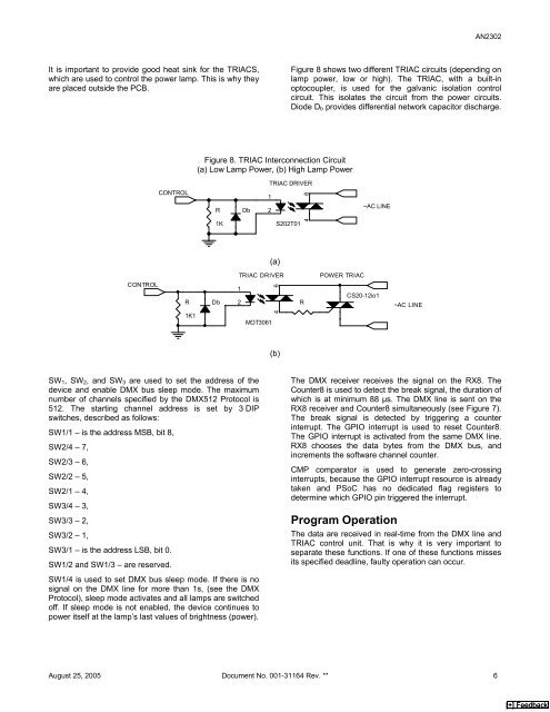
It is important to provide good heat sink for the TRIACS,<br />
which are used to control the power lamp. This is why they<br />
are placed outside the PCB.<br />
CONTROL<br />
CONTROL<br />
R<br />
1K1<br />
Figure 8. TRIAC Interconnection Circuit<br />
(a) Low Lamp <strong>Power</strong>, (b) High Lamp <strong>Power</strong><br />
R Db<br />
1K<br />
Db<br />
1<br />
2<br />
<strong>AN2302</strong><br />
Figure 8 shows two different TRIAC circuits (depending on<br />
lamp power, low or high). The TRIAC, with a built-in<br />
optocoupler, is used for the galvanic isolation control<br />
circuit. This isolates the circuit from the power circuits.<br />
Diode Db provides differential network capacitor discharge.<br />
TRIAC DRIVER<br />
1<br />
2<br />
(a)<br />
TRIAC DRIVER<br />
MOT3061<br />
SW1, SW2, and SW3 are used to set the address of the<br />
device and enable <strong>DMX</strong> bus sleep mode. The maximum<br />
number of channels specified by the <strong>DMX</strong>512 Protocol is<br />
512. The starting channel address is set by 3 DIP<br />
switches, described as follows:<br />
SW1/1 – is the address MSB, bit 8,<br />
SW2/4 – 7,<br />
SW2/3 – 6,<br />
SW2/2 – 5,<br />
SW2/1 – 4,<br />
SW3/4 – 3,<br />
SW3/3 – 2,<br />
SW3/2 – 1,<br />
SW3/1 – is the address LSB, bit 0.<br />
SW1/2 and SW1/3 – are reserved.<br />
SW1/4 is used to set <strong>DMX</strong> bus sleep mode. If there is no<br />
signal on the <strong>DMX</strong> line for more than 1s, (see the <strong>DMX</strong><br />
Protocol), sleep mode activates and all lamps are switched<br />
off. If sleep mode is not enabled, the device continues to<br />
power itself at the lamp’s last values of brightness (power).<br />
6<br />
4<br />
(b)<br />
S202T01<br />
6<br />
4<br />
R<br />
POWER TRIAC<br />
~AC LINE<br />
CS20-12io1<br />
~AC LINE<br />
The <strong>DMX</strong> receiver receives the signal on the RX8. The<br />
Counter8 is used to detect the break signal, the duration of<br />
which is at minimum 88 µs. The <strong>DMX</strong> line is sent on the<br />
RX8 receiver and Counter8 simultaneously (see Figure 7).<br />
The break signal is detected by triggering a counter<br />
interrupt. The GPIO interrupt is used to reset Counter8.<br />
The GPIO interrupt is activated from the same <strong>DMX</strong> line.<br />
RX8 chooses the data bytes from the <strong>DMX</strong> bus, and<br />
increments the software channel counter.<br />
CMP comparator is used to generate zero-crossing<br />
interrupts, because the GPIO interrupt resource is already<br />
taken and PSoC has no dedicated flag registers to<br />
determine which GPIO pin triggered the interrupt.<br />
Program Operation<br />
The data are received in real-time from the <strong>DMX</strong> line and<br />
TRIAC control unit. That is why it is very important to<br />
separate these functions. If one of these functions misses<br />
its specified deadline, faulty operation can occur.<br />
August 25, 2005 Document No. 001-31164 Rev. ** 6<br />
[+] Feedback
![Microchip Signal Chain Design Guide [pdf] - Farnell](https://img.yumpu.com/19262401/1/190x245/microchip-signal-chain-design-guide-pdf-farnell.jpg?quality=85)