Power Management - 6-Channel DMX Dimmer - AN2302 - Farnell
Power Management - 6-Channel DMX Dimmer - AN2302 - Farnell
Power Management - 6-Channel DMX Dimmer - AN2302 - Farnell

You also want an ePaper? Increase the reach of your titles
YUMPU automatically turns print PDFs into web optimized ePapers that Google loves.
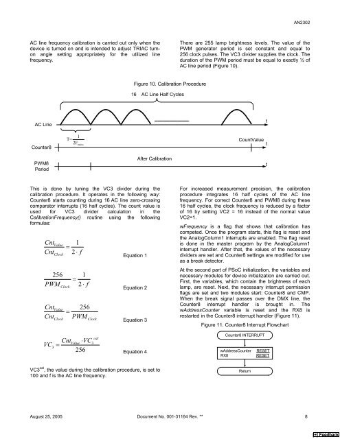
AC line frequency calibration is carried out only when the<br />
device is turned on and is intended to adjust TRIAC turnon<br />
angle setting appropriately for the utilized line<br />
frequency.<br />
AC Line<br />
Counter8<br />
PWM8<br />
Period<br />
Figure 10. Calibration Procedure<br />
16 AC Line Half Cycles<br />
<strong>AN2302</strong><br />
There are 255 lamp brightness levels. The value of the<br />
PWM generator period is set constant and equal to<br />
256 clock pulses. The VC3 divider supplies the clock. The<br />
duration of the PWM period must be equal to exactly ½ of<br />
AC line period (Figure 10).<br />
1<br />
T= CountValue<br />
2Fmains t<br />
After Calibration<br />
This is done by tuning the VC3 divider during the<br />
calibration procedure. It operates in the following way:<br />
Counter8 starts counting during 16 AC line zero-crossing<br />
comparator interrupts (16 half cycles). The count value is<br />
used for VC3 divider calculation in the<br />
CalibrationFrequency() routine using the following<br />
formulas:<br />
CntValue<br />
1<br />
=<br />
Cnt 2 ⋅ f<br />
Clock<br />
Equation 1<br />
256 1<br />
=<br />
PWM Clock 2 ⋅ f<br />
Equation 2<br />
CntValue<br />
256<br />
=<br />
Cnt PWM<br />
VC =<br />
3<br />
Clock Clock<br />
CntValue ⋅VC<br />
256<br />
cal<br />
3<br />
Equation 3<br />
Equation 4<br />
VC3 cal , the value during the calibration procedure, is set to<br />
100 and f is the AC line frequency.<br />
For increased measurement precision, the calibration<br />
procedure integrates 16 half cycles of the AC line<br />
frequency. For correct Counter8 and PWM8 during these<br />
16 half cycles, the clock frequency is reduced by a factor<br />
of 16 by setting VC2 = 16 instead of the normal value<br />
VC2=1.<br />
wFrequency is a flag that shows that calibration has<br />
competed. Once the program starts, this flag is reset and<br />
the AnalogColumn1 interrupts are enabled. The flag reset<br />
is done in the master program by the AnalogColumn1<br />
interrupt handler. After that, the values of the necessary<br />
dividers are set and Counter8 settings are modified for use<br />
as a break detector.<br />
At the second part of PSoC initialization, the variables and<br />
necessary modules for device initialization are carried out.<br />
First, the variables, which contain the brightness of each<br />
lamp, are reset. Next, the necessary interrupt permission<br />
flags are set and two modules start: Counter8 and CMP.<br />
When the break signal passes over the <strong>DMX</strong> line, the<br />
Counter8 interrupt handler is brought in. The<br />
wAddressCounter variable is reset and the RX8 is<br />
restarted in the Counter8 interrupt handler (Figure 11).<br />
Figure 11. Counter8 Interrupt Flowchart<br />
Counter8 INTERRUPT<br />
wAddressCounter RESET<br />
RX8 RESET<br />
August 25, 2005 Document No. 001-31164 Rev. ** 8<br />
Return<br />
t<br />
t<br />
[+] Feedback
![Microchip Signal Chain Design Guide [pdf] - Farnell](https://img.yumpu.com/19262401/1/190x245/microchip-signal-chain-design-guide-pdf-farnell.jpg?quality=85)