Pleur-Evac Operation Manual - Clinical Engineering
Pleur-Evac Operation Manual - Clinical Engineering
Pleur-Evac Operation Manual - Clinical Engineering

You also want an ePaper? Increase the reach of your titles
YUMPU automatically turns print PDFs into web optimized ePapers that Google loves.
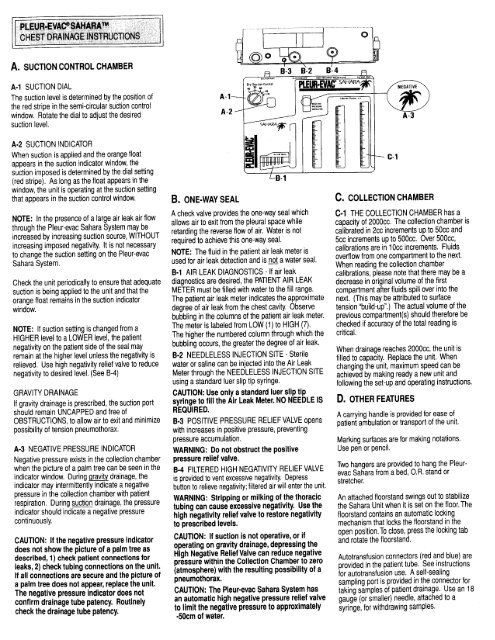
A. SUCTION CONTROL CHAMBER<br />
A-l SUCTION DIAL<br />
The suction level is determined by the position of<br />
the red stripe in the semi-circular<br />
!&ion control<br />
window. Rotate the dial to adjust the desired<br />
suction level.<br />
A-2 SUCTION INDICATOR<br />
When suction is applied and the orange float<br />
appears in the suction indicator window, the<br />
suction imposed is determined by the dial setting<br />
(red stripe). As long as the float appears in the<br />
window, the unit is operating at the suction setting<br />
that appears in the suction control window.<br />
NOTE: In the presence of a large air leak air flow<br />
through the <strong>Pleur</strong>-evac Sahara System may be<br />
increased by increasing suction source, WITHOUT<br />
increasing imposed negativity. It is not necessary<br />
to change the suction setting on the <strong>Pleur</strong>-evac<br />
Sahara System.<br />
Check the unit periodically to ensure that adequate<br />
suction is being applied to the unit and that the<br />
orange float remains in the suction indicator<br />
window.<br />
NOTE: If suction setting is changed from a<br />
HIGHER level to a LOWER level, the patient<br />
negativity on the patient side of the seal may<br />
remain at the higher level unless the negativity is<br />
relieved. Use high negativity relief valve to reduce<br />
negativity to desired level. (See B-4)<br />
GRAVITY DRAINAGE<br />
If gravity drainage is prescribed, the suction port<br />
should remain UNCAPPED and free of<br />
OBSTRUCTIONS, to allow air to exit and minimize<br />
possibility of tension pneumothorax.<br />
A-3 NEGATIVE PRESSURE INDICATOR<br />
Negative pressure exists in the collection chamber<br />
when the picture of a palm tree can be seen in the<br />
indicator window. During gravity drainage, the<br />
indicator may intermittently indicate a negative<br />
pressure in the collection chamber with patient<br />
respiration. During suction drainage, the pressure<br />
indicator should indicate a negative pressure<br />
continuously.<br />
CAUTION: If the negative pressure indicator<br />
does not show the picture of a palm tree as<br />
described, 1) check patient connections for<br />
leaks, 2) check tubing connections on the unit.<br />
If all connections are secure and the picture of<br />
a palm tree does not appear, replace the unit.<br />
The negative pressure indicator does not<br />
confirm drainage tube patency. Routinely<br />
check the drainage tube patency.<br />
Ei-3<br />
b-2<br />
B. ONE-WAY SEAL<br />
A check valve provides the one-way seal which<br />
allows air to exit from the pleural space while<br />
retarding the reverse flow of air. Water is not<br />
required to achieve this one-way seal.<br />
NOTE: The fluid in the patient air leak meter is<br />
used for air leak detection and is not a water seal.<br />
B-l AIR LEAK DIAGNOSTICS - If air leak<br />
diagnostics are desired, the PATIENT AIR LEAK<br />
METER must be filled with water to the fill range.<br />
The patient air leak meter indicates the approximate<br />
degree of air leak from the chest cavity. Observe<br />
bubbling in the columns of the patient air leak meter.<br />
The meter is labeled from LOW (1) to HIGH (7).<br />
The higher the numbered column through which the<br />
bubbling occurs, the greater the degree of air leak.<br />
B-2 NEEDLELESS INJECTION SITE - Sterile<br />
water or saline can be injected into the Air Leak<br />
Meter through the NEEDLELESS INJECTION SITE<br />
using a standard luer slip tip syringe.<br />
CAUTION: Use only a standard luer slip tip<br />
syringe to fill the Air Leak Meter. NO NEEDLE IS<br />
REQUIRED.<br />
B-3 POSITIVE PRESSURE RELIEF VALVE opens<br />
with increases in positive pressure, preventing<br />
pressure accumulation.<br />
WARNING: Do not obstruct the positive<br />
pressure relief valve.<br />
B-4 FILTERED HIGH NEGATIVITY RELIEF VALVE<br />
is provided to vent excessive negativity. Depress<br />
button to relieve negativity; filtered air will enter the unit.<br />
WARNING: Stripping or milking of the thoracic<br />
tubing can cause excessive negativity. Use the<br />
high negativity relief valve to restore negativity<br />
to prescribed levels.<br />
CAUTION: If suction is not operative, or if<br />
operating on gravity drainage, depressing the<br />
High Negative Relief Valve can reduce negative<br />
pressure within the Collection Chamber to zero<br />
(atmosphere) with the resulting possibility of a<br />
pneumothorax.<br />
CAUTION: The <strong>Pleur</strong>-evac Sahara System has<br />
an automatic high negative pressure relief valve<br />
to limit the negative pressure to approximately<br />
40cm of water.<br />
B:4<br />
R<br />
A-3<br />
c. COLLECTION CHAMBER<br />
C-l THE COLLECTION CHAMBER has a<br />
capacity of 2000~~. The collection chamber is<br />
calibrated in 2cc increments up to 5Occ and<br />
5cc increments up to 500~~. Over 5OOcc,<br />
calibrations are in 1 Occ increments. Fluids<br />
overflow from one compartment to the next.<br />
When reading the collection chamber<br />
calibrations, please note that there may be a<br />
decrease in original volume of the first<br />
compartment after fluids spill over into the<br />
next. (This may be attributed to surface<br />
tension “build-up”.) The actual volume of the<br />
previous compartment(s) should therefore be<br />
checked if accuracy of the total reading is<br />
critical.<br />
When drainage reaches 2OOOcc, the unit is<br />
filled to capacity. Replace the unit. When<br />
changing the unit, maximum speed can be<br />
achieved by making ready a new unit and<br />
following the set-up and operating instructions.<br />
D. OTHER FEATURES<br />
A carrying handle is provided for ease of<br />
patient ambulation or transport of the unit.<br />
Marking surfaces are for making notations.<br />
Use pen or pencil.<br />
Two hangers are provided to hang the <strong>Pleur</strong>evac<br />
Sahara from a bed, O.R. stand or<br />
stretcher.<br />
An attached floorstand swings out to stabilize<br />
the Sahara Unit when it is set on the floor. The<br />
floorstand contains an automatic locking<br />
mechanism that locks the floorstand in the<br />
open position. To close, press the locking tab<br />
and rotate the floorstand.<br />
Autotransfusion connectors (red and blue) are<br />
provided in the patient tube. See instructions<br />
for autotransfusion use. A self-sealing<br />
sampling port is provided in the connector for<br />
taking samples of patient drainage. Use an 18<br />
gauge (or smaller) needle, attached to a<br />
syringe, for withdrawing samples.