

Catalog Add On: BETA Low-Voltage Circuit Protection ...
Catalog Add On: BETA Low-Voltage Circuit Protection ...
Catalog Add On: BETA Low-Voltage Circuit Protection ...

Create successful ePaper yourself
Turn your PDF publications into a flip-book with our unique Google optimized e-Paper software.
Occasional surge load from preloading with unknown surge outcome<br />
Specifying the required rated current In of the fuse link is carried out<br />
in two steps:<br />
1. Specifying the rated current In based on the previous load<br />
current Iprev :<br />
1<br />
In > Ivor × ----------------------------------------------------ku<br />
× kq × kλ × kl × WL<br />
Permissible load current I n' of the selected fuse link:<br />
I n' = k u x k q x k λ x k l x WL x I n<br />
2. Checking the permissible overload duration of the surge<br />
current I surge<br />
Melting time t vs (time/current characteristic curves) x<br />
residual value factor RW ≥ surge wave duration t surge<br />
To do this, you require the previous load ratio<br />
V =<br />
Ieff ------<br />
In ′<br />
as well as the characteristic curve "permissible overload and<br />
melting time for previous load" (page 5/58, curve a or b) and the<br />
"time/current characteristic curve" for the selected fuse link.<br />
If a determined overload duration is less than the required overload<br />
duration t surge , then you need to select a fuse link with a greater<br />
rated current I n (taking into account the rated voltage U n and the<br />
permissible breaking I 2 t value) and repeat the check.<br />
La<br />
Load current<br />
'<br />
Condition:<br />
t interval ≥ 3 x t surge<br />
t interval ≥ 5 min<br />
0<br />
J<br />
surge<br />
surge<br />
J interval<br />
Sample selections<br />
For a converter assembly in circuit (B6) A (B6) C, whose rated direct<br />
current is I dn = 850 A, fuse links that can be installed as arm fuses<br />
should be selected. The choice of fuse is shown for different operating<br />
modes of the converter assembly.<br />
Data for converter assembly<br />
Supply voltage<br />
U N = 3 50 Hz 400 V AC<br />
Recovery voltage<br />
U W = 360 V = U N x 0.9 (for shoot-throughs)<br />
Thyristor T 508N (from eupec),<br />
l 2 t value<br />
∫ I 2 dt = 320 x 10 3 A 2 s (10 ms, cold)<br />
Fuse links, natural air cooling<br />
Ambient temperature ϑ u = +35 °C<br />
Conductor cross-section for copper fuse link: 160 mm 2<br />
Conversion factor<br />
Direct current I d/fuse load current I La: I La = I d x 0.58<br />
For the following examples, it is assumed, in the case of loads that<br />
exceed the rated direct current of the converter assembly, that the<br />
converter assembly is rated for this load.<br />
prev<br />
J<br />
I2_12652<br />
© Siemens AG 2007<br />
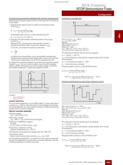
Continuous, no-break load<br />
=<br />
<strong>BETA</strong> Protecting<br />
SITOR Semiconductor Fuses<br />
" ' ! )<br />
Siemens ET B1 AO · 2008, Characteristic curves<br />
Configuration<br />
Direct current Id = Idn = 850 A<br />
ILa = Id x 0.58 = 493 A<br />
Selected:<br />
3NE3 335 SITOR fuse link<br />
(560 A/1000 V), WL = 1<br />
breaking I 2 t value<br />
I 2 tA = 360 x 10 3 x 0.53 = 191 x 10 3 A 2 s<br />
Test cross-section to page 5/54: 400 mm 2<br />
The following correction factors are to be applied:<br />
ku = 1.02 (ϑu = +35 °C)<br />
kq = 0.91 (conductor cross-section, double-ended, 40 % of test<br />
cross-section)<br />
kλ = 1.0 (conduction angle λ = 120°)<br />
kl = 1.0 (no forced-air cooling)<br />
Required rated current In of the SITOR fuse link:<br />
1<br />
In ≥ ILa × ------------------------------------------------- = 493 A<br />
ku × kq × kλ × kl × WL<br />
1<br />
493 A × --------------------------------------------------------------------- = 531 A<br />
102 , × 0, 91 × 10 , × 10 , × 1, 0<br />
Unknown varying load, but with known maximum current<br />
=<br />
= N " ! # )<br />
Max. direct current I dmax = 750 A<br />
Max. fuse current I max = I dmax x 0.58 = 435 A<br />
Selected:<br />
3NE3 334-0B SITOR fuse link<br />
(560 A/1000 V), WL = 1<br />
Breaking I 2 t value<br />
I 2 t A = 260 x 10 3 x 0.53 = 138 x 10 3 A 2 s<br />
Test cross-section to page 5/54: 400 mm 2<br />
The following correction factors are to be applied:<br />
k u = 1.02 (ϑ u = +35 °C)<br />
k q = 0.91 (conductor cross-section, double-ended, 40 % of test<br />
cross-section)<br />
k λ = 1.0 (conduction angle λ = 120°)<br />
k l = 1.0 (no forced-air cooling)<br />
Required rated current I n of the SITOR fuse link:<br />
1<br />
In ≥ Imax × ------------------------------------------------- = 493 A<br />
ku × kq × kλ × kl × WL<br />
1<br />
435 A × --------------------------------------------------------------------- = 469 A<br />
102 , × 0, 91 × 10 , × 10 , × 1, 0<br />
J<br />
J<br />
1 $ # !<br />
1 $ # "<br />
4/63<br />
1<br />
2<br />
3<br />
4<br />
5<br />
6<br />
7<br />
8<br />
9<br />
10<br />
11<br />
12<br />
13<br />
14<br />
15<br />
16<br />
17


