

Catalog Add On: BETA Low-Voltage Circuit Protection ...
Catalog Add On: BETA Low-Voltage Circuit Protection ...
Catalog Add On: BETA Low-Voltage Circuit Protection ...

Create successful ePaper yourself
Turn your PDF publications into a flip-book with our unique Google optimized e-Paper software.
3<br />
<strong>BETA</strong> Protecting<br />
<strong>Low</strong>-<strong>Voltage</strong> Fuse Systems<br />
Introduction<br />
Current limitation<br />
As well as a failsafe rated breaking capacity, the current-limiting<br />
effect of a fuse link is of key importance for the cost effectiveness of<br />
a system. In the event of short-circuit breaking by a fuse, the<br />
breaking current continues to flow through the network until the fuse<br />
link is switched off. However, the breaking current is limited by the<br />
system impedance.<br />
The simultaneous melting of all the bottlenecks of a fuse element<br />
produce a sequence of tiny partial arcs that ensure a fast breaking<br />
operation with strong current limitation. The current limitation is also<br />
strongly influenced by the production quality of the fuse - which in<br />
the case of Siemens fuses is extremely high. For example, an LV<br />
HRC fuse link, size 2 (224 A) limits a breaking current with a possible<br />
r.m.s. value of approximately 50 kA to a let-through current with a<br />
peak value of approx. 18 kA. This strong current limitation provides<br />
constant protection for the system against excessive loads.<br />
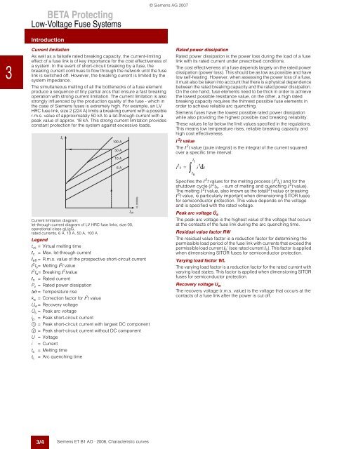
Current limitation diagram;<br />
let-through current diagram of LV HRC fuse links, size 00,<br />
operational class gL/gG,<br />
rated currents, 6 A, 10 A, 50 A, 100 A<br />
Legend<br />
tvs = Virtual melting time<br />
Ic = Max. let-through current<br />
Ieff = R.m.s. value of the prospective short-circuit current<br />
I2ts= Melting I2t value<br />
I2ta = Breaking I2tvalue In = Rated current<br />
Pv = Rated power dissipation<br />
∆ϑ = Temperature rise<br />
ka = Correction factor for I2t value<br />
Uw= Recovery voltage<br />
Ûs = Peak arc voltage<br />
ip = Peak short-circuit current<br />
$ = Peak short-circuit current with largest DC component<br />
% = Peak short-circuit current without DC component<br />
U =<strong>Voltage</strong><br />
i = Current<br />
ts = Melting time<br />
tL = Arc quenching time<br />
3/4<br />
1 c<br />
100 A<br />
50 A<br />
10 A<br />
6 A<br />
1 eff<br />
Siemens ET B1 AO · 2008, Characteristic curves<br />
I2_06998a<br />
© Siemens AG 2007<br />
Rated power dissipation<br />
Rated power dissipation is the power loss during the load of a fuse<br />
link with its rated current under prescribed conditions.<br />
The cost effectiveness of a fuse depends largely on the rated power<br />
dissipation (power loss). This should be as low as possible and have<br />
low self-heating. However, when assessing the power loss of a fuse,<br />
it must also be taken into account that there is a physical dependence<br />
between the rated breaking capacity and the rated power dissipation.<br />
<strong>On</strong> the one hand, fuse elements need to be thick in order to achieve<br />
the lowest possible resistance value, on the other, a high rated<br />
breaking capacity requires the thinnest possible fuse elements in<br />
order to achieve reliable arc quenching.<br />
Siemens fuses have the lowest possible rated power dissipation<br />
while also providing the highest possible load breaking reliability.<br />
These values lie far below the limit values specified in the regulations.<br />
This means low temperature rises, reliable breaking capacity and<br />
high cost effectiveness.<br />
I 2 t value<br />
The I2t value (joule integral) is the integral of the current squared<br />
over a specific time interval:<br />
I 2 t i 2 t1 = dt<br />
∫t0<br />
Specifies the I2t values for the melting process (I2ts) and for the<br />
shutdown cycle (I 2 tA, - sum of melting and quenching I 2 t value).<br />
The melting I2t value, also known as the totalI2t value or breaking<br />
I2t value, is particularly important when dimensioning SITOR fuses<br />
for semiconductor protection. This value depends on the voltage<br />
and is specified with the rated voltage.<br />
Peak arc voltage Ûs The peak arc voltage is the highest value of the voltage that occurs<br />
at the contacts of the fuse link during the arc quenching time.<br />
Residual value factor RW<br />
The residual value factor is a reduction factor for determining the<br />
permissible load period of the fuse link with currents that exceed the<br />
permissible load current In' (see rated current In). This factor is applied<br />
when dimensioning SITOR fuses for semiconductor protection.<br />
Varying load factor WL<br />
The varying load factor is a reduction factor for the rated current with<br />
varying load states. This factor is applied when dimensioning SITOR<br />
fuses for semiconductor protection.<br />
Recovery voltage Uw The recovery voltage (r.m.s. value) is the voltage that occurs at the<br />
contacts of a fuse link after the power is cut off.


