

Catalog Add On: BETA Low-Voltage Circuit Protection ...
Catalog Add On: BETA Low-Voltage Circuit Protection ...
Catalog Add On: BETA Low-Voltage Circuit Protection ...

You also want an ePaper? Increase the reach of your titles
YUMPU automatically turns print PDFs into web optimized ePapers that Google loves.
4<br />
<strong>BETA</strong> Protecting<br />
SITOR Semiconductor Fuses<br />
Configuration<br />
■ Overview<br />
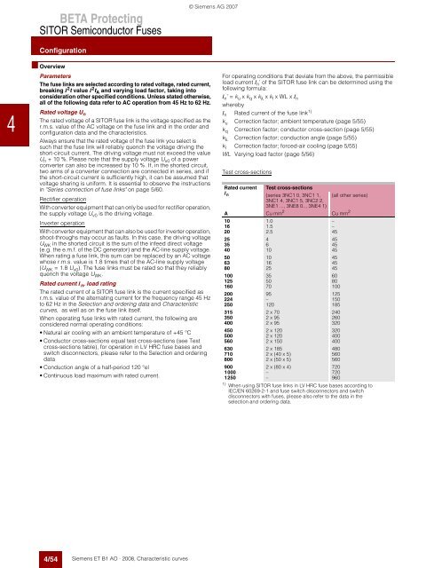
Parameters<br />
The fuse links are selected according to rated voltage, rated current,<br />
breaking I2t value I2tA and varying load factor, taking into<br />
consideration other specified conditions. Unless stated otherwise,<br />
all of the following data refer to AC operation from 45 Hz to 62 Hz.<br />
Rated voltage Un The rated voltage of a SITOR fuse link is the voltage specified as the<br />
r.m.s. value of the AC voltage on the fuse link and in the order and<br />
configuration data and the characteristics.<br />
Always ensure that the rated voltage of the fuse link you select is<br />
such that the fuse link will reliably quench the voltage driving the<br />
short-circuit current. The driving voltage must not exceed the value<br />
Un + 10 %. Please note that the supply voltage Uv0 of a power<br />
converter can also be increased by 10 %. If, in the shorted circuit,<br />
two arms of a converter connection are connected in series, and if<br />
the short-circuit current is sufficiently high, it can be assumed that<br />
voltage sharing is uniform. It is essential to observe the instructions<br />
in "Series connection of fuse links" on page 5/60.<br />
Rectifier operation<br />
With converter equipment that can only be used for rectifier operation,<br />
the supply voltage Uv0 is the driving voltage.<br />
Inverter operation<br />
With converter equipment that can also be used for inverter operation,<br />
shoot-throughs may occur as faults. In this case, the driving voltage<br />
UWK in the shorted circuit is the sum of the infeed direct voltage<br />
(e.g. the e.m.f. of the DC generator) and the AC-line supply voltage.<br />
When rating a fuse link, this sum can be replaced by an AC voltage<br />
whose r.m.s. value is 1.8 times that of the AC-line supply voltage<br />
(UWK = 1.8 Uv0 ). The fuse links must be rated so that they reliably<br />
quench the voltage UWK. Rated current In, load rating<br />
The rated current of a SITOR fuse link is the current specified as<br />
r.m.s. value of the alternating current for the frequency range 45 Hz<br />
to 62 Hz in the Selection and ordering data and Characteristic<br />
curves, as well as on the fuse link itself.<br />
When operating fuse links with rated current, the following are<br />
considered normal operating conditions:<br />
Natural air cooling with an ambient temperature of +45 °C<br />
Conductor cross-sections equal test cross-sections (see Test<br />
cross-sections table), for operation in LV HRC fuse bases and<br />
switch disconnectors, please refer to the Selection and ordering<br />
data<br />
Conduction angle of a half-period 120 °el<br />
Continuous load maximum with rated current.<br />
4/54<br />
Siemens ET B1 AO · 2008, Characteristic curves<br />
© Siemens AG 2007<br />
For operating conditions that deviate from the above, the permissible<br />
load current In ’ of the SITOR fuse link can be determined using the<br />
following formula:<br />
In’ = ku x kq x kλ x kl x WL x In whereby<br />
In Rated current of the fuse link1) ku Correction factor; ambient temperature (page 5/55)<br />
kq Correction factor; conductor cross-section (page 5/55)<br />
kλ Correction factor; conduction angle (page 5/55)<br />
kl Correction factor; forced-air cooling (page 5/55)<br />
WL Varying load factor (page 5/56)<br />
Test cross-sections<br />
Rated current Test cross-sections<br />
In (series 3NC1 0, 3NC1 1,<br />
3NC1 4, 3NC1 5, 3NC2 2,<br />
3NE1 ..., 3NE8 0.., 3NE4 1)<br />
(all other series)<br />
A Cu mm<br />
1)<br />
When using SITOR fuse links in LV HRC fuse bases according to<br />
IEC/EN 60269-2-1 and fuse switch disconnectors and switch<br />
disconnectors with fuses, please also refer to the data in the<br />
selection and ordering data.<br />
2<br />
Cu mm 2<br />
10 1.0 –<br />
16 1.5 –<br />
20 2.5 45<br />
25 4 45<br />
35 6 45<br />
40 10 45<br />
50 10 45<br />
63 16 45<br />
80 25 45<br />
100 35 60<br />
125 50 80<br />
160 70 100<br />
200 95 125<br />
224 – 150<br />
250 120 185<br />
315 2 x 70 240<br />
350 2 x 95 260<br />
400 2 x 95 320<br />
450 2 x 120 320<br />
500 2 x 120 400<br />
560 2 x 150 400<br />
630 2 x 185 480<br />
710 2 x (40 x 5) 560<br />
800 2 x (50 x 5) 560<br />
900 2 x (80 x 4) 720<br />
1000 – 720<br />
1250 – 960


