User's Guide - Toro Media
User's Guide - Toro Media
User's Guide - Toro Media

Create successful ePaper yourself
Turn your PDF publications into a flip-book with our unique Google optimized e-Paper software.
<strong>Toro</strong> Modular Controller - 4 to 24 Stations<br />
♦ Installation<br />
♦ Programming<br />
♦ Operation<br />
%<br />
ON<br />
PREV NEXT<br />
OFF<br />
User’s <strong>Guide</strong>
Introduction<br />
The TMC-424E Series takes modularity to a whole new level. <strong>Toro</strong>’s advanced modular technology<br />
combines sophisticated features with simple operation to provide a customizable controller. Station<br />
count can be 4 – 24 stations, using four-or eight-station modules. Real-time flow sensing monitors up<br />
to three independent sensors and is compatible with the <strong>Toro</strong> TFS Series flow sensors. Versatile run<br />
times allows for additional watering flexibility. Add this together with features like two levels of surge<br />
protection, compatibility with the TMR-1 Maintenance Remote, the rugged dual-use cabinet, and<br />
convenient program review feature, and you really do have the ultimate in controller Flexibility.<br />
TMC-424E controller features:<br />
• Advanced hybrid control module featuring easy-to-use dial interface<br />
• Non-volatile memory–retains program data without battery backup<br />
• Four fully-independent watering programs<br />
• Concurrent operation of up to three automatic programs<br />
• 16 unique start times allotted to programs in any combination of 0–16<br />
• Program cycle and soak option provides 1–30 repeat cycles and soak time delay from 1 second<br />
to 60 minutes<br />
• Day scheduling by Calendar days, 1–31-day Interval or Odd/Even days with<br />
selective day exclusion<br />
• Station run time adjustable form 1 second to 8 hours<br />
• Season Adjust by program and by month from 0–200% (automatic split-cycle watering for adjustment<br />
over 100%)<br />
• Rain delay to postpone automatic watering operation from 1–14 days<br />
• Master valve/pump start operation assignable by program or station<br />
• Programmable well recovery/station delay from 1–60 seconds or 1–60 minutes<br />
• Flow monitoring and alert parameters for 1– 3 flow sensors.<br />
• Output current watchdog feature detects overload/short-circuit condition and automatically<br />
bypasses suspect station(s).<br />
• Optional Normally Open master valve control on flow sensing modules<br />
• Manual operations by station and program<br />
• Review feature quickly recaps all program information<br />
• 12-or 24-hour time designation<br />
• Programming display prompts selectable in English, Spanish, French, German, Italian or<br />
Portuguese<br />
• Valve test feature for quick station and system check<br />
• Equipped for optional <strong>Toro</strong> rain sensor models TRS, TWRS and TWRFS,<br />
<strong>Toro</strong> TMR-1 handheld maintenance remote and <strong>Toro</strong> TFS Series flow sensors.<br />
ii
The unique TMC-424E Expansion Modules are color-coded for easy identification. The modules<br />
can be mixed and matched in any combination and are available in six models as indicated in the<br />
table below.<br />
Model Color Station Surge Surge Flow Flow Monitor Master Valve<br />
Number Code Count Level Icon Monitor Icon Control<br />
TSM-4 Gray 4 Standard No No<br />
TSM-8 Gray 4 Standard No No<br />
TSM-4H Beige 4 High No No<br />
TSM-8H Beige 4 High No No<br />
TSM-4F Blue 4 High Yes Yes<br />
TSM-8F Blue 4 High Yes Yes<br />
The Expansion Modules can be installed and removed at any time without powering down the<br />
controller. The TMC-424E will gain instant access to the module and will logically number the stations<br />
based on module position.<br />
For example, if three 4-station modules are installed, the stations will be numbered 1–12: module I<br />
(stations 1–4) module II (stations 5–8) and module III (stations 9–12). If module II is removed, stations<br />
5–8 will be automatically assigned to module III. All stations will remain in sequence without gaps.<br />
Getting Started<br />
As an initial step, we recommend that you take a few moments to browse through various sections of<br />
this User’s <strong>Guide</strong>. Also, take the time jot down some basic watering program and station information<br />
on the Watering Schedule form provided. Having this information readily at hand will be very helpful<br />
during the initial controller setup and programming procedures.<br />
Note that the Watering Schedule form provides a convenient pocket for the User’s <strong>Guide</strong> and Quick<br />
Reference <strong>Guide</strong> when folded and attached to the inside of the cabinet door.<br />
iii
Table of Contents<br />
Introduction. . . . . . . . . . . . . . . . . . . . . . . . . . . . . . . . . . . . . . . . . . . . . . . . . . . . . . . . . . . . . . . . . . ii<br />
Control Module Overview . . . . . . . . . . . . . . . . . . . . . . . . . . . . . . . . . . . . . . . . . . . . . . . . . . . . . . 2<br />
Internal Component Overview . . . . . . . . . . . . . . . . . . . . . . . . . . . . . . . . . . . . . . . . . . . . . . . . . . 4<br />
Programming Overview. . . . . . . . . . . . . . . . . . . . . . . . . . . . . . . . . . . . . . . . . . . . . . . . . . . . . . . . 5<br />
What is a Watering Program? . . . . . . . . . . . . . . . . . . . . . . . . . . . . . . . . . . . . . . . . . . . . . . . . . 5<br />
What is a Program Watering Cycle? . . . . . . . . . . . . . . . . . . . . . . . . . . . . . . . . . . . . . . . . . . . . 5<br />
What is Armchair Programming TM ?. . . . . . . . . . . . . . . . . . . . . . . . . . . . . . . . . . . . . . . . . . . . . . 5<br />
Controller Programming. . . . . . . . . . . . . . . . . . . . . . . . . . . . . . . . . . . . . . . . . . . . . . . . . . . . . . . 6<br />
Set Current Time and Date . . . . . . . . . . . . . . . . . . . . . . . . . . . . . . . . . . . . . . . . . . . . . . . . . . . 6<br />
Select the Program. . . . . . . . . . . . . . . . . . . . . . . . . . . . . . . . . . . . . . . . . . . . . . . . . . . . . . . . . . 6<br />
Set Station Run Time . . . . . . . . . . . . . . . . . . . . . . . . . . . . . . . . . . . . . . . . . . . . . . . . . . . . . . . . 6<br />
Set Program Start Times . . . . . . . . . . . . . . . . . . . . . . . . . . . . . . . . . . . . . . . . . . . . . . . . . . . . . 7<br />
Set Watering Day Schedule . . . . . . . . . . . . . . . . . . . . . . . . . . . . . . . . . . . . . . . . . . . . . . . . . . . 7<br />
To Set Calendar Days. . . . . . . . . . . . . . . . . . . . . . . . . . . . . . . . . . . . . . . . . . . . . . . . . . . . . 8<br />
To Set Odd or Even Days. . . . . . . . . . . . . . . . . . . . . . . . . . . . . . . . . . . . . . . . . . . . . . . . . . 8<br />
To Set Interval Days . . . . . . . . . . . . . . . . . . . . . . . . . . . . . . . . . . . . . . . . . . . . . . . . . . . . . . 8<br />
Season Adjust Feature . . . . . . . . . . . . . . . . . . . . . . . . . . . . . . . . . . . . . . . . . . . . . . . . . . . . . . . . 9<br />
Special Functions. . . . . . . . . . . . . . . . . . . . . . . . . . . . . . . . . . . . . . . . . . . . . . . . . . . . . . . . . . . . 10<br />
Setting Station Delay Time Option. . . . . . . . . . . . . . . . . . . . . . . . . . . . . . . . . . . . . . . . . . . . . 10<br />
Setting Master Valve/Pump Start Options . . . . . . . . . . . . . . . . . . . . . . . . . . . . . . . . . . . . . . . 10<br />
To Select MV/PS Operation by Program and Station. . . . . . . . . . . . . . . . . . . . . . . . . . . . 11<br />
To Set MV/PS Start Delay . . . . . . . . . . . . . . . . . . . . . . . . . . . . . . . . . . . . . . . . . . . . . . . . 11<br />
To Set MV/PS Operation During Station Delay . . . . . . . . . . . . . . . . . . . . . . . . . . . . . . . . 11<br />
Setting Watering Cycle Repeat Option . . . . . . . . . . . . . . . . . . . . . . . . . . . . . . . . . . . . . . . . . 12<br />
Setting Program Stack/Overlap Option . . . . . . . . . . . . . . . . . . . . . . . . . . . . . . . . . . . . . . . . . 12<br />
Erase Program Memory . . . . . . . . . . . . . . . . . . . . . . . . . . . . . . . . . . . . . . . . . . . . . . . . . . . . . 13<br />
Selecting Handheld Remote Operation . . . . . . . . . . . . . . . . . . . . . . . . . . . . . . . . . . . . . . . . . 13<br />
Selecting Display Language Option . . . . . . . . . . . . . . . . . . . . . . . . . . . . . . . . . . . . . . . . . . . . 13<br />
12/24-hour Time Display Option. . . . . . . . . . . . . . . . . . . . . . . . . . . . . . . . . . . . . . . . . . . . . . . 13<br />
Selecting Run Time Format . . . . . . . . . . . . . . . . . . . . . . . . . . . . . . . . . . . . . . . . . . . . . . . . . . 13<br />
iv
Manual Operations. . . . . . . . . . . . . . . . . . . . . . . . . . . . . . . . . . . . . . . . . . . . . . . . . . . . . . . . . . .14<br />
Manual Station Operations. . . . . . . . . . . . . . . . . . . . . . . . . . . . . . . . . . . . . . . . . . . . . . . . . . .14<br />
True Manual Operation . . . . . . . . . . . . . . . . . . . . . . . . . . . . . . . . . . . . . . . . . . . . . . . . . . .14<br />
Timed Manual Operation. . . . . . . . . . . . . . . . . . . . . . . . . . . . . . . . . . . . . . . . . . . . . . . . . .14<br />
Manual Program Operations . . . . . . . . . . . . . . . . . . . . . . . . . . . . . . . . . . . . . . . . . . . . . . . . .15<br />
Single Program Operation. . . . . . . . . . . . . . . . . . . . . . . . . . . . . . . . . . . . . . . . . . . . . . . . .15<br />
Multiple Program Operation . . . . . . . . . . . . . . . . . . . . . . . . . . . . . . . . . . . . . . . . . . . . . . .15<br />
Flow Sensor Operations . . . . . . . . . . . . . . . . . . . . . . . . . . . . . . . . . . . . . . . . . . . . . . . . . . . . . .16<br />
Select Fill Delay Option . . . . . . . . . . . . . . . . . . . . . . . . . . . . . . . . . . . . . . . . . . . . . . . . . . . . .16<br />
Select Flow Sensor Module Master Valve Type . . . . . . . . . . . . . . . . . . . . . . . . . . . . . . . . . .17<br />
Select Flow Rate Alert Thresholds. . . . . . . . . . . . . . . . . . . . . . . . . . . . . . . . . . . . . . . . . . . . .17<br />
Rain Sensor Control Features . . . . . . . . . . . . . . . . . . . . . . . . . . . . . . . . . . . . . . . . . . . . . . . . .18<br />
Rain Sensor Timed Bypass . . . . . . . . . . . . . . . . . . . . . . . . . . . . . . . . . . . . . . . . . . . . . . . . . .18<br />
Rain Sensor Control by Program . . . . . . . . . . . . . . . . . . . . . . . . . . . . . . . . . . . . . . . . . . . . . .19<br />
Valve Test Feature . . . . . . . . . . . . . . . . . . . . . . . . . . . . . . . . . . . . . . . . . . . . . . . . . . . . . . . . . . .19<br />
Rain Delay Feature. . . . . . . . . . . . . . . . . . . . . . . . . . . . . . . . . . . . . . . . . . . . . . . . . . . . . . . . . . .20<br />
Program Review Function. . . . . . . . . . . . . . . . . . . . . . . . . . . . . . . . . . . . . . . . . . . . . . . . . . . . .20<br />
Installation Instructions. . . . . . . . . . . . . . . . . . . . . . . . . . . . . . . . . . . . . . . . . . . . . . . . . . . . . . .21<br />
Cabinet Installation. . . . . . . . . . . . . . . . . . . . . . . . . . . . . . . . . . . . . . . . . . . . . . . . . . . . . . . . .21<br />
Field Wire Connections . . . . . . . . . . . . . . . . . . . . . . . . . . . . . . . . . . . . . . . . . . . . . . . . . . . . .22<br />
Flow Sensor Connection . . . . . . . . . . . . . . . . . . . . . . . . . . . . . . . . . . . . . . . . . . . . . . . . . . . .23<br />
Power Connection – Indoor Models. . . . . . . . . . . . . . . . . . . . . . . . . . . . . . . . . . . . . . . . . . . .24<br />
Power Connection – Outdoor Models . . . . . . . . . . . . . . . . . . . . . . . . . . . . . . . . . . . . . . . . . .25<br />
Rain Sensor Installation (Optional). . . . . . . . . . . . . . . . . . . . . . . . . . . . . . . . . . . . . . . . . . . . .26<br />
<strong>Toro</strong> TMR-1 Handheld Remote Installation (Optional). . . . . . . . . . . . . . . . . . . . . . . . . . . . . .27<br />
Appendix A – TFS Flow Sensor Performance Data . . . . . . . . . . . . . . . . . . . . . . . . . . . . . . . .28<br />
Appendix B – TMC-424E Current Load Data . . . . . . . . . . . . . . . . . . . . . . . . . . . . . . . . . . . . . .29<br />
Appendix C – Display Alerts. . . . . . . . . . . . . . . . . . . . . . . . . . . . . . . . . . . . . . . . . . . . . . . . . . .30<br />
Appendix D – Default Settings - Abbreviations . . . . . . . . . . . . . . . . . . . . . . . . . . . . . . . . . . .31<br />
Specifications . . . . . . . . . . . . . . . . . . . . . . . . . . . . . . . . . . . . . . . . . . . . . . . . . . . . . . . . . . . . . . .32<br />
The <strong>Toro</strong> Promise - Limited Warranty Information. . . . . . . . . . . . . . . . . . . . . . . . . . . . . . . . .33<br />
FCC Compliance Information . . . . . . . . . . . . . . . . . . . . . . . . . . . . . . . . . . . . . . . . . . . . . . . . . .36<br />
Customer Care You Can Count On . . . . . . . . . . . . . . . . . . . . . . . . . . . . . . . . . . . . . . . . . . . . .36<br />
v
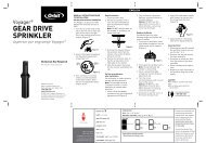
Control Module Overview<br />
The following brief descriptions of the controller components and display elements are provided<br />
for general overview. Each of these items are explained in detail within the appropriate section of<br />
this guide.<br />
1 - Program Switch<br />
Four-position slide switch used to select<br />
program A, B, C and D for set up, review<br />
and manual control.<br />
2 - Digital Display<br />
a - Station run time icon.<br />
b - Start time icon.<br />
c - Program identifiers.<br />
d - Prompt displayed with Interval schedule<br />
length<br />
e - Flow sensor icon displayed with flow<br />
sensor expansion module<br />
f - % symbol displayed when the<br />
Season Adjust function is active.<br />
g - Water drop icon indicates current<br />
watering activity. Icon with slash<br />
indicates automatic operation is disabled<br />
(Off, station disabled or Rain Delay<br />
function.<br />
h - Prompt displayed to indicate<br />
current day within an Interval watering<br />
day schedule.<br />
i - Expansion module dock identifier<br />
(I, II and III, left to right).<br />
j - Hollow circles represent the station<br />
terminals of an installed 4-or 8-station<br />
expansion module. Station positions of<br />
the current operating station or stations<br />
assigned to a program are indicated by<br />
a solid circle.<br />
k - Indicates the station number or start<br />
time number is currently shown in<br />
the 2-digit numeric display (directly<br />
above).<br />
2<br />
l - 2-digit display identifies the<br />
station number or start time number<br />
currently selected.<br />
3 - Navigation Buttons<br />
The and buttons are used to select<br />
function menu items.<br />
All numeric, On/Off, and Yes/No values<br />
are selected with the and buttons.<br />
4 - Function Dial<br />
Turns in either direction to select the<br />
following operating, control, and programming<br />
functions:<br />
run – The normal position for<br />
automatic controller operations.<br />
current time/day – To set clock time,<br />
day and date.<br />
station times – To set station<br />
run time.<br />
start times – To set program start<br />
times.<br />
calendar days – To set<br />
program watering day schedule by days<br />
of the week.<br />
odd/even – To set program<br />
watering day schedule by Odd or Even<br />
numbered days.<br />
season adjust – To adjust run time of all<br />
stations within a program and/or program<br />
within a month from 0 to 200% in 10%<br />
increments.<br />
special functions – To select specialized<br />
setup and programming options<br />
(see page 10 for details).<br />
sensors – To select flow sensor<br />
operation setup parameters.
manual program – To operate<br />
watering programs manually.<br />
manual station – To operate individual<br />
stations manually.<br />
valve test – To manually test valve<br />
operating sequence using a temporary run<br />
time.<br />
review – To recap all program information<br />
including: start times, run times,<br />
and season adjust %.<br />
OFF – Shuts off and prevents all<br />
automatic and manual watering operations.<br />
c d e f g<br />
b<br />
1<br />
a<br />
5<br />
2<br />
l<br />
k<br />
j<br />
4<br />
PREV NEXT<br />
5 - 9V Battery Compartment & Clip<br />
%<br />
A standard 9V battery is required for<br />
Armchair Programming TM and to maintain<br />
clock time during an extended power loss.<br />
ON<br />
OFF<br />
3<br />
h<br />
i<br />
3
Internal Component Overview<br />
6<br />
6 - Power supply compartment cover.<br />
7 - Control module ribbon cable receptacle.<br />
8 - Transformer 24 VAC output connection<br />
terminals<br />
9 - MR-1 remote connection port.<br />
10 - Rain sensor bypass switch.<br />
11 - Auxiliary port (not enabled).<br />
12 - Flow sensor expansion module<br />
(model TSM-8F indicated).<br />
13 - Flow sensor wiring terminals<br />
14 - Flow module master valve<br />
wiring terminal.<br />
15 - Expansion module valve<br />
wiring terminals.<br />
4<br />
7<br />
8<br />
9<br />
10<br />
17<br />
11<br />
19 18 16<br />
16 - Expansion module<br />
(model TSM-4 shown).<br />
17 - Wiring connection terminals:<br />
S - Rain Sensor (2).<br />
Hot Post (24 VAC source)<br />
P - Pump Start/Master Valve<br />
C - Valve (field) Common (2)<br />
18 - Optional Earth Ground Lug<br />
Attachment Screw.<br />
19 - Input power wire connection<br />
terminals:.<br />
L - Line (mains 1)<br />
N - Neutral (mains 2)<br />
- Ground<br />
12<br />
13<br />
14<br />
15
Programming Overview<br />
What is a watering program?<br />
In basic terms, a watering program is a small set of instructions that tells the controller which days will<br />
be active for watering, when to start a watering cycle, and how long each station will operate during<br />
the cycle. The TMC-424E series has four independent watering programs identified as A, B, C, and D.<br />
Separate programs are usually used to group stations with similar landscape or watering attributes<br />
or to provide a way to segment specific site conditions, such as north-facing slopes or shaded turf<br />
areas. As you can see, the availability of four programs allows you to have unique watering programs<br />
for your varied landscape needs. Multiple programs can be designated to operate one at a time or<br />
can overlap operated in sequence or concurrently with up to three programs at the same time as you<br />
choose. This feature enables more watering to be completed within the prime watering time, which is<br />
generally between midnight and 6:00 a.m.<br />
What is a program watering cycle?<br />
When a program start time is selected, that time becomes the beginning of an automatic watering<br />
cycle. A watering cycle operates each station with an assigned run time duration in the program,<br />
one by one, in numeric sequence from the lowest to the highest station number.<br />
The TMC-424E provides up to 16 watering cycle start time slots that can be assigned to the four<br />
programs in any combination. For example, program A could have 10 start times, program B two<br />
start times, program C four start times and program D no start times. Any combination up to 16<br />
start times is permitted.<br />
NOTE: A Watering Schedule Form is provided for your convenience. Use this form to plan and<br />
record your automatic watering information. Keep the card handy for reference by attaching it<br />
inside the cabinet cover.<br />
What is Armchair Programming TM ?<br />
A 9V battery can be installed, enabling the control module to be fully programmed prior to installation<br />
– in the comfort of your favorite easy chair.<br />
1. Slide and lock the expansion module(s) into position.<br />
2. Attach a 9V battery to the control module battery clip and stow the battery in the slot provided.<br />
(See item 5 on page 3.)<br />
3. With the Function Dial in the RUN position, press the button to acquire the expansion<br />
module configuration (note the displayed module identifier).<br />
4. To remove the control module from the cabinet, disconnect the ribbon cable at the cabinet,<br />
then press the top hinge in to release the module.<br />
5. Program the controller starting at Setting Current Time and Date on page 6.<br />
NOTE: The 9V battery powers the microprocessor during an extended AC interruption. Once<br />
programmed, the battery can be removed or remain installed as preferred. Controller output<br />
requires AC power input.<br />
5
Controller Programming<br />
NOTE: English display prompts and 12-hour (a.m./p.m.) time format are factory-default settings. To<br />
select an optional display language, including Spanish, French, Italian, German and Portuguese,<br />
and/or a 24-hour time format, refer to the Special Function setup procedures on page 13.<br />
Set Current Time and Date<br />
1. Turn the Function Dial clockwise to Current Time/Day . The hour digits will begin flashing.<br />
2. Adjust the display by pressing the or buttons.<br />
NOTE: Hold either button down for rapid advance.<br />
3. Press the button to select the next field.<br />
4. Repeat steps 2 and 3 to set the current minutes, year, month and day (current weekday will<br />
be set based on calendar setting).<br />
5. Return the Function Dial to RUN when finished.<br />
Select the Program<br />
NOTE: If the controller has been previously programmed, the user-defined program settings can be<br />
quickly erased and reset to factory defaults. See “Using the Program Memory Erase Feature” on<br />
page 13.<br />
To simplify the programming process, the following procedures are provided to define the<br />
operating parameters of one program at a time.<br />
To begin, set the program switch to select program A, B, C, or D.<br />
Set Station Run Time<br />
A station is assigned to the selected program when it is given a run time duration. The station can<br />
have only one run time assignment per program, but can have a separate run time assignment in<br />
each program. By default, station run time is defined in minutes and hours. To enable station run<br />
time to include seconds, see “Station Runtime Display Format” on page 13.<br />
1. Turn the Function Dial to Station Times .<br />
2. Press the or button to select the station number. The corresponding station output<br />
terminal will be shown on the display as a solid circle.<br />
3. Press the or buttons to adjust the station run time from Off (-- -- --) to 1 minute – 8<br />
hours (in 1-minute increments). If seconds format is enabled, station run time can be set from<br />
01–60 seconds.<br />
NOTE: Hold either button down for rapid advance.<br />
4. Repeat steps 2 and 3 for all stations to be assigned to the selected program.<br />
6
Set Program Start Times<br />
NOTE: The TMC-424E enables a total of 16 unique start times to assigned to four programs<br />
in any combination totaling 16. For example, program A could have 12 start time assignments,<br />
which would leave four start time assignments available for programs B, C and D.<br />
1. Turn the Function Dial to Start Times . The start time hour digit(s) will begin flashing.<br />
2. Press the or button to select a start time number (01 to 16).<br />
NOTE: Any start time number currently assigned to another program can not be selected. If all 16<br />
start time assignments are in use, NONE will be displayed.<br />
3. Press the or button to select a start time hour (note the correct a.m./p.m. designation in<br />
the 12-hour clock mode).<br />
NOTE: To remove a start time, select -- --:-- -- (Off), located between the hours of 11:00 p.m.<br />
and 12:00 a.m. (00 minutes).<br />
4. Press the button to select minutes digits. Repeat step 3 to set start time minutes (00–59).<br />
5. Repeat steps 2–4 to set additional start times for the selected program.<br />
Set Watering Day Schedule<br />
The TMC-424E series offers three watering day schedule formats. Each program can have any one<br />
of the following schedule formats:<br />
Calendar Days – Use this scheduling method to select specific days of the week.<br />
Odd/Even – Schedules days by odd-or even-numbered calendar days.<br />
NOTE: When an odd-numbered day schedule is used, watering will not occur on the 31st of any<br />
month and February 29th of a leap year.<br />
Day Interval – Scheduling by Day Interval enables a specific number of days between watering to<br />
be selected. For example, selecting a 1-day Interval<br />
schedules watering to occur every day. A 2-day interval schedules watering<br />
to occur every-other day. A 31-day interval is the maximum schedule, providing watering only<br />
once every 31 days. Since the interval schedule is not tied to<br />
specific days of the week, you will also need to determine when the interval<br />
will start, by selecting the current day within the Interval.<br />
• Day Exclusion – When using the Odd/Even or Day Interval watering day schedule, watering<br />
will not always occur on the same days each week.<br />
To prevent watering on a specific days, for example, watering-restricted days, specific days of<br />
the week can be easily excluded from the schedule.<br />
NOTE: Each program can only have one assigned watering schedule format.<br />
If either an Interval or Odd/Even schedule is currently set, it must be turned Off first to enable an<br />
optional format to be selected.<br />
7
To Set Calendar Days:<br />
1. Turn the Function Dial to Calendar Days .<br />
2. Sunday will be displayed and selected to water indicated by the water icon. To exclude the<br />
day from the schedule, press the or button to display the No Water icon.<br />
3. Press the button to select the next day.<br />
4. Repeat step 2 and 3 to schedule the remaining days of the week.<br />
To Set Odd or Even Days:<br />
1. Turn the Function Dial to the Odd/Even position.<br />
2. Press the or button to select ODD or EVEN.<br />
3. To exclude specific days from watering, press the button to select the day.<br />
4. To exclude the day from the schedule, press the or button to display the No Water<br />
icon.<br />
5. To exclude additional days (7 maximum), repeat steps 4 and 5.<br />
To Set Interval Days:<br />
1. Turn the Function Dial to Interval Days .<br />
2. The CYCLE LENGTH prompt and the current Interval (01–31 DAY or -- -- -- [Off]) will be<br />
displayed.<br />
3. Press the or button to select the Interval cycle length.<br />
NOTE: The cycle length can be set from 01 (water every day) to 31 (water once every 31 days).<br />
The Interval cycle starts at 01 and increases by 1 digit each day. The watering day occurs when<br />
the selected Interval cycle length is reached.<br />
To specify when the first watering day will occur, the current day within the Interval cycle must be<br />
selected. For example, if a 04 DAY Interval is entered and watering is to begin in one day, select<br />
03 as the Current Day.<br />
4. To select the Current Day in the Interval cycle, press the button to display the<br />
CURRENT DAY prompt.<br />
5. Press the or button to select the value (01–selected Interval number).<br />
6. To exclude specific days from watering (7 maximum), press the button to select the day.<br />
7. To exclude the day from the schedule, press the or button to display the<br />
No Water icon.<br />
8. Repeat steps 6 and 7 to continue excluding days.<br />
STOP – This concludes the basic program setup procedures. Repeat these procedures<br />
starting at “Select the Program” on page 6 for each program you wish set up at this<br />
time.<br />
8
Season Adjust Feature<br />
The Season Adjust feature enables the cumulative program run time to be easily increased or<br />
decreased by a percentage factor from 0% (Off) – 200%, in 10% increments. Season Adjust can<br />
be applied to individual programs and globally to all programs by selected months of the year.<br />
When a Season Adjust factor is applied by program and by month, the adjusted program duration is<br />
the result of the combined percentage factors.<br />
For example, program A has a total station run duration of 60 minutes with an 80% Season Adjust<br />
value applied to the program. The adjusted run time for<br />
program A is 48 minutes. In addition, a 50% Season Adjust value is applied to<br />
the month of December. The resulting cumulative run time for program A during December will be 24<br />
minutes.<br />
Example: 60 minutes x 80% (.80) = 48 minutes x 50% (.50) = 24 minutes.<br />
NOTE: By selecting the program Review function, you can instantly view the total run time of<br />
each program adjusted for all operating factors including: timed delays, repeat cycles and Season<br />
Adjust %. See “Program Review Feature” on page 20 for additional information.<br />
1. Set the Program Switch to select program A, B, C, or D.<br />
2. Turn the Function Dial to Season Adjust .<br />
3. Press the or button to adjust the % value for the selected program.<br />
NOTE: Adjusting the % value to Off prevents operation of the program.<br />
NOTE: As a runoff-prevention measure, selecting a Season Adjust % factor over 100% will<br />
automatically split the adjusted program run time in half and run a repeat (back-to-back)<br />
program watering cycle.<br />
4. Press the button to select Season Adjust (for all programs) by month<br />
(01 = Jan, 02 = Feb, etc).<br />
5. Press the or button adjust the % value.<br />
NOTE: Adjusting the % value to Off prevents operation of all programs for the entire month.<br />
NOTE: The % symbol will be displayed to indicate when a Season Adjust % factor is applied.<br />
9
Special Functions<br />
The following program setup options and control parameters are provided in the<br />
Special Functions dial position.<br />
NOTE: To review the factory default settings for each function, refer to “Appendix D - Controller<br />
Default Settings” on page 31.<br />
• Set delay period between sequential stations within a program cycle<br />
• Set Pump Start/Master Valve operation by specific programs<br />
• Set Pump Start/Master Valve operation for specific stations<br />
• Set delay period between pump start/master valve and station sequence<br />
• Set Pump Start/Master Valve operation during station delay<br />
• Set program cycle repeat and delay options<br />
• Select program stacking or overlap options<br />
• Erase program memory by specific program<br />
• Set handheld remote control option<br />
• Select display language format<br />
• Select 12- or 24-hour clock format<br />
• Select station time<br />
• View controller firmware version.<br />
Setting Station Delay Time Option<br />
This feature enables a delay period to be entered between sequential stations within a watering cycle.<br />
This option is generally used when irrigation demand exceeds the supply capacity, as can occur when<br />
the supply is pumped from a well or reservoir. The delay period is adjustable from Off to 59 seconds<br />
in 1-second increments, or 1 to 60 minutes in 1-minute increments.<br />
1. Set the Program Switch to select program A, B, C, or D.<br />
2. Turn the Function Dial to Special Functions .<br />
3. Press the button (as needed) to display SD -- -- -- (Station Delay – Off).<br />
4. Press the or button to select the delay time.<br />
NOTE: The time value will change from seconds to minutes as the display scrolls past 59<br />
seconds. Minutes value is displayed as 1M – 60M.<br />
Setting Master Valve/Pump Start Options<br />
The TMC-424E allows you to set Master Valve/Pump Start (MV/PS) operation by individual<br />
program and by individual station as preferred. By default, operation of all programs and all<br />
stations will activate the MV/PS circuit. The following procedures are primarily used to exclude<br />
specific programs and/or stations from MV/PS operation.<br />
10
NOTE: A program must have the MV/PS control option enabled to permit individual stations<br />
assigned to the program to be excluded from MV/PS operation. In other words, assigning MV/PS<br />
operation by station is not applicable unless MV/PS operation for its assigned program is enabled.<br />
• Master Valve/Pump Start Operation by Program<br />
1. Set the Program Switch to select program A, B, C, or D.<br />
2. Turn the Function Dial to Special Functions .<br />
3. Press the button to display MVA -- Y (Master Valve [program A] - Yes [on]).<br />
4. To exclude the selected program from MV/PS operation, press the or button to select<br />
MV[A] – N (Master Valve [program A] – No).<br />
• Master Valve/Pump Start Operation by Station<br />
1. Press the button to display MVS -- N (Master Valve Stations – No).<br />
2. To access this option, the option must first be enabled by pressing the<br />
or button to select MVS -- Y (Yes). By default, all station identifiers will be solid circles<br />
(all enabled).<br />
3. Press the button to select MV -- Y 01 (Master Valve--Yes, station 01).<br />
The station identifier will begin flashing.<br />
4. Press the button to exclude selected station, or press the button to skip the station.<br />
When excluded, the station identifier will change from solid to hollow. The next station identifier<br />
in sequence will begin flashing.<br />
5. Repeat the procedure in step 4 as needed for each station.<br />
• To Set Pump Delay<br />
This feature enables a delay period from 1 to 60 seconds to occur after the MS/PS circuit is activated,<br />
and prior to the start of the first station in the watering sequence. This delay feature is often used in<br />
conjunction with the Station Delay (SD) feature.<br />
1. Set the Program Switch to select program A, B, C, or D.<br />
2. Turn the Function Dial to Special Functions .<br />
3. Press the button (as needed) to display PD -- -- (Pump Delay Off).<br />
4 . Press the or button to select the delay time value from 01 to 60 seconds.<br />
• To Set Pump Enable<br />
This feature allows you to enable or disable MV/PS operation for the duration of a Station Delay<br />
period.<br />
1. Set the Program Switch to select program A, B, C, or D.<br />
2. Turn the Function Dial to Special Functions .<br />
3. Press the button as needed to display PE - - N (Pump Enable - No [Off]).<br />
4. Press the or button to select PE - - Y (Pump Enable - Yes [On]).<br />
11
Setting Watering Cycle Repeat Option<br />
This option enables a program watering cycle to automatically repeat operation<br />
from 1 to 30 times per program start.<br />
1. Set the Program Switch to select program A, B, C, or D.<br />
2. Turn the Function Dial to Special Functions .<br />
3. Press the button as needed to display CYC --N (Cycle [repeat] - No [Off]).<br />
4. Press the or button to select CYC --Y (Cycle [repeat] - Yes [On]).<br />
5. Press the button once to display RPT – – (Repeat (none).<br />
6. Press the or button to select the number of repeat cycles from 01–30<br />
(1 repeat = 2 watering cycles).<br />
7. Press the button to select DL -- -- -- (delay period between repeat cycles).<br />
8. Press the or button to select the delay period, Off (– – –) to 59 seconds in 1-second<br />
increments or 1–60 minutes in 1-minute increments.<br />
Setting Program Stack/Overlap Option<br />
This option determines if multiple programs will be constrained to single-file operation (stacked) or<br />
enabled to operate 2 or 3 programs concurrently (overlap).<br />
CAUTION: Before selecting the overlap option, ensure the hydraulic capacity of the<br />
irrigation system and the controller’s maximum current load will not be exceeded when<br />
multiple stations (including master valve/pump start circuits) operate concurrently.<br />
Refer to “Appendix B – TMC-424E Current Load Data” on page 29 for additional<br />
information.<br />
1. Turn the Function Dial to Special Functions .<br />
2. Press the button as needed to display 1PROG (stack).<br />
3. Press the or buttons to select 2PROG or 3PROG (overlap).<br />
NOTE: When operating multiple programs in the stacked mode, any watering cycle that extends<br />
past midnight into the next day will continue operating until finished. However, any program cycle<br />
start times remaining in queue after the day change to an unscheduled watering day, will be<br />
canceled. This rule applies to all automatic and manual operations.<br />
12
Erase Program Memory<br />
Erasing the program memory will remove all user-defined information including run times, start<br />
times and day schedule from a specified program. Additionally, all control options specified for the<br />
program will be reset to factory defaults.<br />
1. Set the Program Switch to select program A, B, C, or D.<br />
2. Turn the Function Dial to Special Functions .<br />
3. Press the button as needed to display ERASE.<br />
4. Press the button once to display OK? To initiate the erase function, press the button<br />
again to display DONE.<br />
Selecting Handheld Remote Operation<br />
The TMC-424E is equipped for use with the <strong>Toro</strong> TMR-1 handheld remote.<br />
By default, remote control operation is enabled. To disable operation with TMR-1 receiver, using<br />
the following procedure.<br />
1. Turn the Function Dial to Special Functions .<br />
2. Press the button as needed to display HH – Y (Hand Held – Yes)<br />
3. Press the or buttons to select HH – N (Hand Held – No).<br />
Selecting Display Language Option<br />
The TMC-424E displays word prompts in English (ENG) by default and offers five additional<br />
languages preferences as follows: Spanish (ESP), French (FRA), Italian (ITA), German (DEU) and<br />
Portuguese (POR).<br />
1. Turn the Function Dial to Special Functions .<br />
2. Press the button as needed to display ENG (or the current language).<br />
3. Press the or buttons to select the desired language.<br />
Selecting 12/24-hour Time Display Option<br />
This feature enables the clock time display to be changed from 12-hour (am./p.m.) format to a 24-hour<br />
clock format.<br />
1. Turn the Function Dial to Special Functions .<br />
2. Press the button as needed to display 12H.<br />
3. Press the or buttons to select 24H.<br />
Selecting Run Time Format<br />
This feature enables the station run time to be selected in seconds increments<br />
in addition to minutes and hours increments.<br />
1. Turn the Function Dial to Special Functions .<br />
2. Press the button as needed to display SEC – N (Seconds – No).<br />
3. Press the or buttons to select SEC – Y (Seconds – Yes).<br />
13
Manual Operations<br />
The TMC-424E offers several manual operation methods. A separate Function Dial position is<br />
provided for Manual Station and Manual Program operations<br />
NOTE: All program control options selected within Special Functions will also apply to all manual<br />
control operations.<br />
Manual Station Operations<br />
The TMC-424E offers two ways to manually activate individual stations: True manual, to operate a<br />
selected station without a specified run time, and Timed manual to operate selected stations with<br />
an assigned temporary run time.<br />
• True Manual Operation<br />
1. Turn the Function Dial to Manual Station .<br />
2. Press the button as needed to select the station number.<br />
3. Press the button to turn on the station. ON will be displayed with the icon.<br />
NOTE: The station will run continuously until a navigation button is pressed or the Function<br />
Dial is turned. The station will turn off automatically at Midnight.<br />
IMPORTANT: Flow thresholds do not apply during True Manual and Timed Manual<br />
operations.<br />
• Timed Manual Operation<br />
1. Turn the Function Dial to Manual Station .<br />
2. Press the button to select the station number.<br />
3. Press the or buttons to select a manual run time (1 minute – 8 hours).<br />
4. To select additional stations, repeat steps 2 and 3.<br />
5. When station selections have been made, turn the Function Dial to RUN .<br />
14<br />
• The operating station number(s), remaining station run time and the icon (flashing) will<br />
begin alternating with the current time of day.<br />
• The stations will operate in the order selected, either sequentially or concurrently as determined<br />
by the Stack/Overlap option selection.<br />
• Automatic mode will resume when the manual operation has been completed.<br />
• To advance through the station sequence, press the button.<br />
• To terminate manual operation at any time, turn the Function Dial to OFF .<br />
When the display stops flashing, turn the dial to RUN .
Manual Program Operations<br />
This type of manual watering is also known as “Semi-automatic” operation. When a program is<br />
started manually, it runs through the watering cycle as if started automatically. A single program<br />
can be operated, or multiple programs can be run in sequence or simultaneously.<br />
NOTE: All automatic program control options selected within Special Functions will also apply to<br />
all manual operations.<br />
• Single Program Operation<br />
1. Turn the Function Dial to Manual Program .<br />
2. Set the Program Switch to select program A, B, C, or D. The program letter and MAN will be<br />
displayed. All stations assigned to the program will be indicated by solid circles.<br />
3. Press the button to start the watering cycle. The first station in sequence will turn on. The<br />
program identifier and icon will begin flashing.<br />
4. Turn the Function Dial to RUN .<br />
• The operating station number, remaining station run time and the icon (flashing) will begin<br />
alternating with the current time of day.<br />
• The stations will operate one at a time in numeric sequence.<br />
• Automatic mode will resume when the manual operation is finished.<br />
• To turn off an active station and start the next station in sequence, press the button.<br />
• To end manual operation at any time, turn the Function Dial to OFF , wait for the display to<br />
stop flashing, then turn the dial to RUN .<br />
• Multiple Program Operation<br />
1. Turn the Function Dial to Manual Program .<br />
2. Set the Program Switch to select program A, B, C, or D.<br />
3. Press the button to start (or queue) the program. The program identifier and icon will<br />
begin flashing.<br />
4. To select additional programs, repeat steps 2 and 3.<br />
5. Turn the Function Dial to RUN .<br />
• The operating program identifier, station number(s), remaining station run time and icon<br />
will begin alternating with the current time of day.<br />
• The programs will operate in the order selected, either sequentially or concurrently as<br />
determined by the Stack/Overlap option selection.<br />
• Automatic mode will resume when the manual operation is finished.<br />
• To turn off an active station and start the next station in sequence, position the Program Switch<br />
(if needed) to select the program, then press the button.<br />
• To end manual operation at any time, turn the Function Dial to OFF . When the display<br />
stops flashing, turn the dial to RUN .<br />
15
Flow Sensor Operations<br />
Flow monitoring is one of the best water resource management tools available in the irrigation<br />
industry today. With definable under-, over- and critical-flow limits set, broken lateral or mainline<br />
piping, stuck valves or damaged sprinklers can be quickly detected and bypassed automatically.<br />
The TMC-424E accepts up to three flow-sensing expansion modules (flow modules) that enable<br />
the controller to read, store and compare flow rate data from individual flow meters. Each station<br />
connected to flow-enabled expansion module has the option of being flow monitored.<br />
After a defined delay period (Fill Delay), a flow measurement is taken. If the station flow rate<br />
exceeds any of the established thresholds, an alert is triggered; the station is bypassed and<br />
operated at the next scheduled watering time.<br />
After inserting a flow-sensor expansion module, the flow sensor icon is displayed and the<br />
following control features become accessible:<br />
• Select flow sensing operations by individual station<br />
• Automatically read and learn the flow rate of each station<br />
• Measure flow as part of normal irrigation operation<br />
• Set lower, upper and critical flow thresholds<br />
• Immediately disable station and flow module master valve operation if flow rate exceeds a<br />
critical flow threshold.<br />
NOTE: The actual or “Learned” flow rate for each station should be established prior to setting alert<br />
thresholds. To perform this operation, the Valve Test function, True Manual or Timed Manual station<br />
operations can be used to operate each station for a two-minute run time required to establish the<br />
Learned flow rate.<br />
Flow Module Setup Procedure<br />
NOTE: The TMC-424E is designed for use with <strong>Toro</strong> TFS series flow sensors only. Consult with<br />
an authorized <strong>Toro</strong> distributor prior to connecting other flow sensor makes. For complete TFS flow<br />
sensor installation and setup information, refer to the user’s guide provided with the unit.<br />
• Select Fill Delay option:<br />
The fill delay period helps prevent false sensor readings caused by initial turbulence within long<br />
main line runs. Fill delay setting postpones flow sampling up to 9 minutes after irrigation begins.<br />
1. Turn the Function Dial to Sensors .<br />
2. Set the Program Switch to select program A, B, C, or D.<br />
3. Press the button as needed to display FIL: 0M (Fill delay – 0 minutes).<br />
4. Press the or button to select a delay period (1 – 9 minutes in 1-minute increments or<br />
leave at 0M if a fill delay is not required.<br />
5. Repeat this procedure for each program as needed, starting at step 2.<br />
16
• Select Flow Sensor Module Master Valve Type<br />
1. Press the button to display MV:NC (Master Valve: Normally Closed). If the flow module<br />
does not control a master valve, press the button twice to skip this setting.<br />
NOTE: When multiple flow sensor modules are installed, the first module in sequence will be<br />
selected (designated by the flow sensor icon ). To change the module selection, press<br />
the or button.<br />
2. To change the master valve type to Normally Open, press the or button to select<br />
MV:NO (Master Valve: Normally Open).<br />
NOTE: A Normally Open master valve must be energized to remain closed. Therefore, the<br />
master valve will remain open when the controller is idle. However, if a flow alert is triggered,<br />
the master valve (controlled by the flow sensor module) will be energized (closed).<br />
• To set flow rate alert thresholds:<br />
1. Press the button to display NF -- -- (Nominal Flow – Off). Nominal flow threshold is the<br />
maximum allowable flow while the controller is idle. A flow alert is triggered if flow is detected<br />
above this setting.<br />
2. Press the or button to select a value from 01 to 99 PPS (pulses per second).<br />
Select -- -- (Off) to disable this threshold.<br />
NOTE: Refer to page 28 for important flow sensor performance data.<br />
3. Press the button to display CLR:LF (Clear: Learned Flow).<br />
• To retain the current learned flow value, press the button to skip this setting.<br />
• To clear the current learned flow value, press the button to display OK?.<br />
Press the button again. Continue when DONE is displayed.<br />
4. Press the button to display FLO -- N (Flow – No), flow sensing option for the<br />
selected station.<br />
• To enable flow sensing for the selected station, press the or button to display<br />
FLO–Y (Flow –Yes).<br />
• To bypass flow sensing for the selected station, press the button.<br />
The next station in sequence will be selected.<br />
NOTE: Flow sensing setup parameters (Over-flow, Under-flow, Critical-flow and Learned-flow)<br />
are available only to stations that have flow sensing enabled.<br />
5. Press the button to select OF -- -- (Over Flow – Off). This setting establishes the alert<br />
threshold for a flow rate above the Learned Flow.<br />
6. Press the or button to select a value from 10–100%, (in 10% increments).<br />
Select -- -- to disable this threshold.<br />
(continued)<br />
17
7. Press the button to select UF -- -- (Under Flow – Off). This setting establishes the alert<br />
threshold for a flow rate below the Learned Flow.<br />
8. Press the or button to select a value from 10–100%, (in 10% increments).<br />
Select -- -- to disable this threshold.<br />
9. Press the button to select CF -- -- (Critical Flow – Off). This setting establishes the alert<br />
threshold for a flow rate above the Learned Flow.<br />
10. Press the or button to select a value from 10–100% (in 10% increments).<br />
Select -- -- to disable this threshold.<br />
NOTE: If a Critical Flow alert is triggered, operation of all stations (and master valve)<br />
monitored by the flow sensor will be immediately terminated.<br />
11. Press the button to select Learned Flow (LF). If the Learned flow rate has been previously<br />
established, the PPS value is displayed. If the Learned flow has not been established, the<br />
display will indicate LF -- --.<br />
NOTE: The learned flow rate for each station (assigned to flow monitoring) will be automatically<br />
recorded the first time it is operated.<br />
For PPS/GPM conversion information, see chart on page 28.<br />
12. Press the button. Repeat the flow sensor setup parameters for each station starting at<br />
step 4 on page 17.<br />
Rain Sensor Control Features<br />
Rain Sensor Timed Bypass<br />
Rain sensor input can be manually overridden by placing the sensor control switch in the bypass<br />
position (see item 10, page 4). An alternate method of controlling rain sensor input is by enabling<br />
the Timed Bypass feature. When enabled, Timed Bypass overrides rain sensor input and sensor<br />
bypass switch function, enabling the controller to continue irrigation operations regardless of rain<br />
sensor input.<br />
By default, the Timed Bypass mode is Off until it is enabled. Once enabled, rain sensor input<br />
will be bypassed for the remainder of the day. At midnight, Timed Bypass mode is terminated,<br />
enabling normal rain sensor operations to resume.<br />
1. Turn the Function Dial to Sensors . TBP - N (Timed Bypass – No) is selected by default.<br />
2. Press the or button to select TBP-Y (Timed Bypass – Yes).<br />
18
Rain Sensor Control by Program<br />
This unique TMC-424E feature enables rain sensor control input to be enabled/disabled for specific<br />
programs. By default rain sensor input is active for all programs.<br />
1. Turn the Function Dial to Sensors .<br />
2. Set the Program Switch to select program A, B, C, or D.<br />
3. Press the button as needed to select RS(A) - - Y (Rain Sensor [program A] Yes (default).<br />
4. Press the or button to select RS(A ) - - N (Timed Bypass – No).<br />
5. Repeat steps 2–4 for each program as required.<br />
Valve Test Feature<br />
This feature allows you to quickly operate of each station for short period of time for a convenient<br />
initial system check, periodic maintenance, spring start-up etc.<br />
The preset time for each station is two minutes but can be quickly adjusted from 30 seconds to 10<br />
minutes as desired.<br />
NOTE: Only stations with a run time (assigned to any program) will be included in the<br />
test operation.<br />
IMPORTANT: Flow thresholds do not apply during Valve Test operation.<br />
1. Turn the Function Dial to Valve Test . The display will show 2 M (2 minutes) of run time<br />
per station.<br />
2. Press the or buttons to change the run time of all stations from 30 seconds<br />
to 10 minutes.<br />
3. Press the button. The program identification letter will begin flashing and water on icon will<br />
be displayed.<br />
4. Turn the Function Dial to RUN . All station numbers with assigned run time in any program<br />
will be displayed. The currently operating station number and the icon will be flashing.<br />
The stations will operate one at a time in numeric sequence. The automatic mode will resume<br />
when the valve test operation is finished.<br />
NOTE: To turn off an active station and start the next station in sequence, press the button.<br />
Review operation will be terminated when the last station number displayed has completed it’s<br />
run time or has been skipped.<br />
To terminate operation at any time, turn the Function Dial to OFF . Wait for display to stop<br />
flashing, then turn the dial to RUN .<br />
19
Rain Delay Feature<br />
The Rain Delay and Season Adjust control features enable quick, temporary changes in operation to<br />
help compensate for changes in weather and season.<br />
Rain Delay enables all automatic watering operations to be delayed from 1 to 14 days.<br />
For example, rain is forecast in your area for the next two days. Instead of turning the controller off<br />
and possibly forgetting to turn it back on, a 3-day delay can be easily set. At the end of 3 days, the<br />
controller will resume automatic operation as scheduled.<br />
1. Turn the Function Dial to OFF .<br />
2. Press the or button to select the number of days to delay operation from 1 to 14.<br />
3. Turn the Function Dial to RUN .<br />
NOTE: OFF and the number of rain delay days remaining until automatic<br />
operation resumes will be displayed (alternating with the current time). The rain delay day<br />
number will decrease by one at each day change.<br />
Automatic operation will resume when the watering delay day number is no longer displayed.<br />
4. To terminate the rain delay function, turn the Function Dial to OFF .<br />
5. Press the button until only OFF is displayed.<br />
6. Turn the Function Dial to RUN .<br />
Program Review Feature<br />
The Program Review feature provides a convenient method of reviewing all user-defined<br />
programming information.<br />
Program elements will be displayed as follows:<br />
• Total program cycle duration, factored for Season Adjust %, delays and repeats.<br />
• Total irrigation time (time irrigation actually occurs), factored for Season Adjust %, delays<br />
and repeats.<br />
• Watering day schedule type (Calendar, Odd/Even of Interval)<br />
• Program start times<br />
• Station run times<br />
• Rain Sensor assignment by program<br />
• All flow settings (when flow sensing option is used).<br />
1. Turn the Function Dial to Review .<br />
2. Set the Program Switch to select the program to be reviewed.<br />
3. Press the button to index through the program information.<br />
4. When finished, turn the Function Dial to RUN .<br />
20
Installation Instructions<br />
Preparing the Cabinet for Installation<br />
1. Swing open the timing mechanism to access the internal components and wiring access holes.<br />
2. Five wiring access holes are provided in the bottom of the cabinet as follows:<br />
A- 1/2" (13mm) for power and equipment ground wires.<br />
B- Two 1/2" (13mm) knock-outs for the optional rain sensor or handheld remote wiring.<br />
C- Two 3/4" (19mm) 1" (25mm) knock-outs for field wires.<br />
NOTE: Removing all applicable knock-out plugs prior to cabinet installation is recommended.<br />
NOTE: Install electrical conduit as specified by applicable electrical and/or building codes.<br />
(Wire, electrical conduit and conduit fittings are not provided.)<br />
Selecting an Appropriate Installation Site<br />
A B C<br />
Select an installation site for the TMC-424E controller that will provided the following conditions:<br />
• Protection from direct exposure to irrigation spray, midday sun, wind and snow.<br />
• Access to all field and optional accessory wiring.<br />
• Access to a grounded AC power source that is not controlled by a light switch or shared by a<br />
major appliance, motor-driven equipment.<br />
• (Indoor controller models only) – within 4' (1.2m) of a grounded electrical outlet.<br />
21
Cabinet Installation<br />
1. Drive a wood screw into the wall within eye<br />
level until only 1/4" (10mm) of the screw is<br />
exposed.<br />
NOTE: If installing the controller on drywall or<br />
masonry, install the appropriate type screw<br />
anchors.<br />
2. Hang the cabinet on the screw using the<br />
keyhole slot.<br />
3. Open the controller cabinet and swing open<br />
the timing mechanism to access the lower<br />
mounting screw location.<br />
4. Install the lower mounting screw in the hole<br />
provided and tighten securely.<br />
5. Fill out the provided Watering Schedule form with program and system details. Affix the provided<br />
hook and loop disks to the form in the designated locations. Attach the form to the inside of the<br />
cabinet cover.<br />
Field Wire Connections<br />
NOTE: Using 14–18 AWG (2–1mm2 ) multi-strand irrigation hookup cable for<br />
field wire connections is recommended. This cable is made specifically for underground installation<br />
and is available in various lengths and conductor count. Select a cable that has at least one<br />
conductor for each valve connection and one conductor to provide a valve common connection.<br />
1. Route the valve control wires between the valves and the controller.<br />
2. Attach the white wire to either lead from each valve solenoid to provide a valve common wire.<br />
3. Attach a separate wire to the remaining valve solenoid lead of each valve.<br />
NOTE: For reference when making wire connections at the controller, note of the wire color<br />
used for each control valve connection and the corresponding watering zones.<br />
4. Secure all wire splices using water-proof wire connectors or any appropriate method of<br />
protecting wire splices from direct contact with soil or moisture.<br />
5. Route the cable into the controller through one of the 3/4" (19mm) access holes in the base<br />
of the housing or through the PVC conduit (if installed). Strip insulation back 3/8” (10mm) for<br />
wiring terminal connections.<br />
6. Secure the field common wire(s) to common terminal(s) (C).<br />
7. Secure the individual valve wires to the appropriate expansion module station output terminals<br />
8. Connect one wire from the master valve or pump start relay to terminal (P).<br />
22<br />
7"<br />
(17,78mm)
Pump Start/<br />
Master Valve<br />
Valve<br />
Common<br />
Valve Common Wire<br />
Pump Start Relay Master Valve<br />
CAUTION: To avoid possible equipment damage, do not connect pump starter directly<br />
to the controller. A 24V, 0.5A (maximum) relay must be used for this connection.<br />
Flow Sensor Connection<br />
1. Route the flow sensor wires into the controller cabinet.<br />
2. Connect the flow sensor wires to the flow-enabled expansion module as follows: Black to<br />
negative (–) and Red to positive (+).<br />
NOTE: Flow Sensor wiring polarity must be correct to enable operation.<br />
Black (–) Red (+) Master<br />
Valve<br />
Flow Sensor Master Valve<br />
3. If the master valve circuit is used, connect either solenoid wire to the MV terminal and the<br />
remaining wire to either common terminal (C).<br />
NOTE: The master valve circuit is controlled by operation of the corresponding expansion<br />
module only.<br />
23
Input Power Connection - Indoor Models<br />
NOTE: Unlike most indoor-type controller models, the TMC-424E-ID model incorporates an internal<br />
transformer. A Class C power cord and strain relief are supplied for connection of the transformer<br />
terminal block to a grounded wall outlet.<br />
1. Remove the transformer compartment<br />
cover secured by two phillips screws.<br />
2. Referring to the illustration, install the strain<br />
relief and tighten securely using appropriate<br />
hand tools.<br />
NOTE: Power cord assembly will vary by<br />
controller model.<br />
3. Insert the power cord through the strain<br />
relief.<br />
4. Connect the power cord wires<br />
to the terminal block as follows:<br />
120 VAC Models:<br />
Black to L, White to N and Green<br />
to ground .<br />
230 VAC Models:<br />
Brown to L, Blue to N and Green/Yellow<br />
to ground .<br />
5. Tighten the bottom strain relief nut using an appropriate hand tool. Pull lightly on the power<br />
cord to confirm proper retention.<br />
24<br />
Black or<br />
Brown<br />
White or<br />
Blue<br />
Green/<br />
Yellow
Input Power Connection - Outdoor Models<br />
WARNING: AC power wiring must be installed and connected by qualified personnel<br />
only. All electrical components and installation procedures must comply with all applicable<br />
electrical codes. Some codes may require a means of disconnection from the AC<br />
power source installed in the fixed wiring and having a contact separation of at least<br />
0.120” (3mm) in the line and neutral poles. Make sure the power source is OFF prior to<br />
connecting the controller.<br />
1. Remove the transformer compartment cover secured by two phillips screws.<br />
2. Install 1/2" (13mm) conduit from the power supply to the controller.<br />
3. Route the AC power and equipment ground wires from the power source, through the conduit<br />
and into the transformer compartment.<br />
NOTE: The controller terminal block accepts wire size up to 12 AWG (3mm 2 ).<br />
4. Secure the wires to the terminal block as follows: Hot or Mains 1 to L, Neutral or Mains 2 to N<br />
and equipment ground to .<br />
5. Reinstall the transformer compartment cover and apply power to the controller.<br />
Black or<br />
Blue<br />
White or Blue<br />
Green/<br />
Yellow<br />
Ground Lug and Earth Ground<br />
Connection (optional)<br />
NOTE: In lightning-prone areas, an earth-ground connection may be necessary to provide<br />
adequate surge protection. An (optional) ground lug can be easily installed to facilitate a<br />
ground wire connection. Contact your local <strong>Toro</strong> irrigation distributor for specific grounding<br />
recommendations.<br />
25
Rain Sensor Installation (Optional)<br />
All <strong>Toro</strong> rain sensors, including wireless models TWRS and TWFRS (rain/freeze), and wired version<br />
TRS, can be connected directly to the TMC-424E to automatically interrupt irrigation when the preset<br />
rain or (freeze) threshold is met.<br />
A sensor bypass switch is provided to override sensor operation as needed. Refer to page 18 for<br />
additional Rain Sensor operating information.<br />
When the sensor absorbs moisture, it signals the TMC-424E to suspend automatic watering operations.<br />
While irrigation is suspended, SEN is displayed. When the sensor automatically resets (or is<br />
bypassed) enabling the controller to return to automatic operation, the controller will return to normal<br />
program operation.<br />
1. Route the sensor wires from the device into the controller housing through the provided<br />
access hole.<br />
2. Remove the jumper wire installed between the sensor terminals.<br />
3. Connect the white wire to the top sensor (S) terminal. Connect the brown wire to the<br />
remaining sensor (S) terminal. Connect one (either) red wire to the Hot Post, and the<br />
remaining red wire to a station common (C) terminal.<br />
4. Set the sensor switch to the Sensor Active position.<br />
5. Refer to the instructions provided with the rain sensor for detailed installation and set up<br />
information.<br />
26<br />
– White Wire<br />
– Brown Wire<br />
– Red Wire<br />
– Red Wire<br />
TWRFS<br />
Receiver
<strong>Toro</strong> TMR-1 Handheld Remote Installation (Optional)<br />
The TMC-424E is equipped for operation with the <strong>Toro</strong> TMR-1 handheld remote control. A<br />
handheld control option is provided in Special Functions that enables/disables handheld operation.<br />
By default operation is enabled. Refer to page 13 to disable handheld remote operation.<br />
1. Install the TMR-1 remote receiver plug assembly according to the user’s guide provided with<br />
the TMR-1 kit.<br />
2. Route the receiver power wires and control cable into the cabinet through one of the available<br />
knock-out access holes.<br />
3. Connect either power wire to the Hot Post terminal, and the remaining power wire to a station<br />
common (C) terminal.<br />
4. Plug the RJ-11 connector into the Handheld Remote Port receptacle.<br />
TMR-1<br />
Receiver<br />
Receiver<br />
Plug<br />
5. For complete handheld remote operating information, refer to the user’s guide provided with<br />
the TMR-1 kit.<br />
27
Appendix A – TFS Series Flow Sensor Performance Data<br />
Sensor Model TFS-050 TFS-075 TFS-100 TFS-150 TFS-200 TFS-300 TFS-400<br />
Size<br />
1/2"<br />
(13mm)<br />
3/4" 1.0"<br />
(19mm) (25mm)<br />
1.5" 2.0" 3.0"<br />
(38mm) (51mm) (76mm)<br />
4.0"<br />
(102mm)<br />
K Value 00.78 0.1563 0.26112 1.699 2.8249 8.309 13.74283<br />
Offset 0.9 0.9 1.2 -3.016 0.1435 0.227 0.23707<br />
Min. GPM 1.5 3 5 5 10 20 40<br />
Max. GPM<br />
10 20 30 100 200 300 500<br />
Learned Flow<br />
(PPS)<br />
Equivalent GPM *<br />
5 0.5 1.0 1.7 8.0 14.7 43.5 72.0<br />
10 0.5 1.8 3.0 16.5 28.9 85.0 140.7<br />
15 1.3 2.5 4.3 25.0 43.1 126.6 209.5<br />
20 1.7 3.3 5.6 33.5 57.3 168.1 278.2<br />
25 2.1 4.1 6.9 42.0 71.5 209.7 346.9<br />
30 2.5 4.9 8.2 50.5 85.7 251.2 415.6<br />
35 2.9 5.7 9.5 59.0 100.0 292.8 484.3<br />
40 3.2 6.4 10.8 67.5 114.2 334.0 553.0<br />
45 3.6 7.2 12.1 76.0 128.4 375.8 621.7<br />
50 4.0 8.0 13.4 84.5 142.6 417.4 690.4<br />
55 4.4 8.8 14.7 93.0 156.8 458.9 759.2<br />
60 4.8 9.6 16.0 101.5 171.0 500.5 827.9<br />
65 5.2 10.4 17.3 109.9 185.2 542.2 889.6<br />
70 5.6 11.1 18.6 118.4 199.5 583.6 965.3<br />
75 6.0 11.9 19.9 126.9 231.7 625.1 1034.0<br />
80 6.4 12.7 21.3 135.4 227.9 666.7 1102.7<br />
85 6.8 13.5 22.6 143.9 242.1 708.2 1171.4<br />
90 7.1 14.3 23.9 152.4 256.3 749.7 1240.2<br />
95 7.5 15.0 25.2 160.9 270.5 791.3 1308.9<br />
100 7.9 15.8 26.5 169.4 284.7 832.8 1377.6<br />
105 8.3 16.6 27.8 177.9 299.0 874.4 1446.3<br />
110 8.7 17.4 29.1 186.4 313.2 915.9 1515.0<br />
115 9.1 18.2 30.4 194.9 327.4 957.5 1583.7<br />
120 9.5 18.9 31.7 203.4 341.6 999.0 1652.4<br />
125 9.9 19.7 33.0 211.9 355.8 1040.6 1721.2<br />
NOTE:<br />
• = Do not operate in this region<br />
• TMC-424E maximum PPS = 125<br />
• To convert GPM to LPM, multiply x 3.79<br />
• If installed flow sensor measures in units other than PPS, contact your <strong>Toro</strong> distributor for<br />
assistance.<br />
28
Appendix B – TMC-424E Current Load Data<br />
Determining Maximum Current Load<br />
The reference table below provides various current load combinations that may be encountered<br />
when using multiple programs running simultaneously with Master Valve/Pump Start control<br />
options.<br />
The number of 24 VAC loads based on one station/valve operating per program are listed in the<br />
Station Valves row. The Master Valve and Pump Start values are based on one load per circuit<br />
and one or two Flow Modules each utilizing the individual Master Valve control output.<br />
TMC-424E – Output Current Load<br />
Station Valves<br />
Master Valves<br />
Pump Start<br />
Total Current<br />
Acceptable Marginal Exceeds Limit<br />
NOTE: The maximum total current load permitted is 1.20A @24 VAC. The valve and relay loads<br />
shown in the chart are based on 0.30A @ 24 VAC (nominal). Actual current draw will vary with<br />
make, model, configuration, and size of valves and/or relays utilized. Refer to the manufacturer’s<br />
electrical specifications and recalculate the maximum number of loads permitted based on actual<br />
values.<br />
29
Appendix C: Display Alerts<br />
FUSE – Station and MV/PS output alert<br />
The TMC-424E features built-in circuit protection to help prevent damage to the controller caused<br />
by an over-current condition on any output terminal.<br />
If the controller detects an overload condition, it will bypass the affected output and display the<br />
word FUSE with the affected station number identifier(s). All remaining stations will operate as<br />
programmed for automatic operation.<br />
If the condition occurs on the Pump Start/Master Valve circuit, all stations using the master valve<br />
will prompt the FUSE message.<br />
To clear the warning, press any button. The controller will continue to operate as scheduled and<br />
will attempt to run all stations as programmed.<br />
IMPORTANT: Clearing the display does not correct the problem. The controller will<br />
retry the affected station(s) at each programmed watering cycle and bypass the affected<br />
station(s) until the problem is corrected.<br />
Before continuing to operate the controller, identify and correct the source of the problem.<br />
In most cases, the FUSE alert condition is caused by a faulty valve solenoid, pump start<br />
relay and/or shorted wire splice.<br />
FLOW or NFLOW – Flow sensor alarms<br />
When flow monitoring is used, the FLOW error message will be displayed when a station<br />
experiences an over-, under-, or critical-flow error. In this event, the station is skipped, and the<br />
next programmed station in sequence is operated.<br />
Error message NFLOW is displayed if the Nominal flow threshold (flow measured while controller<br />
is idle) is exceeded. When a Normally Open master valve is controlled by the flow module, it will<br />
be activated (valve closed).<br />
To clear the warning, press any button. The controller will continue to operate as scheduled and<br />
will attempt to run all stations as programmed.<br />
SEN – Rain sensor active<br />
When the rain sensor is active and all controller outputs are off, the SEN prompt is displayed.<br />
Rain sensor input can be bypassed with the controller’s Sensor Bypass switch, the Timed<br />
Bypass feature and rain sensor receiver controls. For complete information regarding rain sensor<br />
operation, refer to the user’s guide provided with the TWRS/TWRFS units.<br />
PAUSE – Watering suspended by TMR-1 handheld remote<br />
When irrigation is paused using the TMR-1 handheld remote, PAUSE will be displayed.<br />
NOTE: If an optional Display Language is in use, – x – will be shown.<br />
30
Appendix D: Default Settings - Abbreviations<br />
When the TMC-424E is shipped from the factory, or the control module has been restored to<br />
factory default settings, the following control parameters are selected:<br />
NOTE: The program default settings, indicated by an asterisk (*), are restored by the Erase feature<br />
provided within Special Functions.<br />
Factory Default Abbreviation<br />
Current Time – 12:00 a.m.. . . . . . . . . . . . . . . . . . . . . . . . . . . . . . . . . . . . . . . . . . . . n/a<br />
Month – January. . . . . . . . . . . . . . . . . . . . . . . . . . . . . . . . . . . . . . . . . . . . . . . . . . . JAN<br />
Year – 2008 . . . . . . . . . . . . . . . . . . . . . . . . . . . . . . . . . . . . . . . . . . . . . . . . . . . . . . n/a<br />
Day – 1. . . . . . . . . . . . . . . . . . . . . . . . . . . . . . . . . . . . . . . . . . . . . . . . . . . . . . . . . . n/a<br />
*Station Times – All Off . . . . . . . . . . . . . . . . . . . . . . . . . . . . . . . . . . . . . . . . . . . . . n/a<br />
*Start Times – All Off . . . . . . . . . . . . . . . . . . . . . . . . . . . . . . . . . . . . . . . . . . . . . . . n/a<br />
*Calendar Days – All On . . . . . . . . . . . . . . . . . . . . . . . . . . . . . . . . . . . . . . . . . . . . n/a<br />
*Odd/Even Days – All Off (no excluded days). . . . . . . . . . . . . . . . . . . . . . . . . . . . n/a<br />
*Interval Days – All Off (no excluded days). . . . . . . . . . . . . . . . . . . . . . . . . . . . . . INT<br />
*Season Adjust – 100% (program and month) . . . . . . . . . . . . . . . . . . . . . . . . . . . 100 %<br />
*Station Delay – No (All Off) . . . . . . . . . . . . . . . . . . . . . . . . . . . . . . . . . . . . . . . . . SD - -<br />
*Master Valve Operation by Program – Yes (All on) . . . . . . . . . . . . . . . . . . . . . . . MV[A] -Y<br />
Master Valve Exclusion by Station – No (No stations excluded) . . . . . . . . . . . . . . MVS - N<br />
*Pump Delay – No (All Off) . . . . . . . . . . . . . . . . . . . . . . . . . . . . . . . . . . . . . . . . . . PD - -<br />
*Pump Enable – No (All Off during station delay) . . . . . . . . . . . . . . . . . . . . . . . . . PE - N<br />
*Cycle Repeats/Delays – No (All Off) . . . . . . . . . . . . . . . . . . . . . . . . . . . . . . . . . . CYC - N<br />
Simultaneous Programs – 1 (stacked) . . . . . . . . . . . . . . . . . . . . . . . . . . . . . . . . . . 1PROG<br />
Handheld Remote Operation – Yes (On). . . . . . . . . . . . . . . . . . . . . . . . . . . . . . . . HH -Y<br />
Display Language – English. . . . . . . . . . . . . . . . . . . . . . . . . . . . . . . . . . . . . . . . . . ENG<br />
Clock Time Format – 12-hour (a.m./p.m). . . . . . . . . . . . . . . . . . . . . . . . . . . . . . . . 12H<br />
Seconds Time Increments – No (Off). . . . . . . . . . . . . . . . . . . . . . . . . . . . . . . . . . . SEC - N<br />
Timed Bypass – No (Off) . . . . . . . . . . . . . . . . . . . . . . . . . . . . . . . . . . . . . . . . . . . . TBP - N<br />
*Rain Sensor/Program – Yes (All On) . . . . . . . . . . . . . . . . . . . . . . . . . . . . . . . . . . RS[A] - Y<br />
*Main Line Fill (delay) – 0 Minutes . . . . . . . . . . . . . . . . . . . . . . . . . . . . . . . . . . . . FIL:0M<br />
Master Valve (type) – NC (Normally Closed). . . . . . . . . . . . . . . . . . . . . . . . . . . . . MV:NC<br />
Nominal Flow – All Off . . . . . . . . . . . . . . . . . . . . . . . . . . . . . . . . . . . . . . . . . . . . . . NF - -<br />
Assign Station to Flow Sensor – No (All Off) . . . . . . . . . . . . . . . . . . . . . . . . . . . . . FLO - N<br />
Overflow – All Off . . . . . . . . . . . . . . . . . . . . . . . . . . . . . . . . . . . . . . . . . . . . . . . . . . OF - -<br />
Underflow – All Off . . . . . . . . . . . . . . . . . . . . . . . . . . . . . . . . . . . . . . . . . . . . . . . . . UF - -<br />
Critical Flow – All Off . . . . . . . . . . . . . . . . . . . . . . . . . . . . . . . . . . . . . . . . . . . . . . . CF - -<br />
Learned Flow – All Off . . . . . . . . . . . . . . . . . . . . . . . . . . . . . . . . . . . . . . . . . . . . . . LF - -<br />
Rain Delay – Off. . . . . . . . . . . . . . . . . . . . . . . . . . . . . . . . . . . . . . . . . . . . . . . . . . . OFF<br />
31
Specifications<br />
Cabinet Dimensions:<br />
• 10.5” W x 9.5” H x 5” D<br />
Temperature Limits:<br />
• Operating: +14°F to +140°F (-10°C to +60°C)<br />
• Storage: -22°F to +149°F (-30°C to +65°C)<br />
Power Specifications:<br />
• North America<br />
Internal Transformer, Class 2, UL Listed, CSA Certified (or equivalent)<br />
Input: 120 VAC ± 10%, 50/60 Hz<br />
Output: 24 VAC ± 10%, 50/60 Hz, 30 VA<br />
• Europe and Australia<br />
Internal Transformer, TUV Approved, SAA Approved<br />
Input: 230 VAC ± 10%, 50/60 Hz<br />
Output: 24 VAC ± 10%, 50/60 Hz, 30 VA<br />
• Maximum Load Per Station:<br />
0.5A @ 24 VAC<br />
• Maximum Load Per Pump/Master Valve Circuit:<br />
0.5A @ 24 VAC<br />
• Total Maximum Load:<br />
1.20A @ 24 VAC<br />
Surge Protection<br />
• TSM-4 and TSM-8<br />
6.0 KV common mode; 600 V normal mode<br />
• TSM-4H, TSM-8H, TSM-4F and TSM-8F:<br />
6.0 KV common mode; 6.0 KV normal mode<br />
Battery Type:<br />
• 9V Alkaline (not included)<br />
32
The <strong>Toro</strong> Promise — Limited Five-Year Warranty<br />
The <strong>Toro</strong> Company and its affiliate, <strong>Toro</strong> Warranty Company, pursuant to an agreement between<br />
them, jointly warrants, to the owner, each new piece of equipment (featured in the current catalog<br />
at date of installation) against defects in material and workmanship for a period described below,<br />
provided they are used for irrigation purposes under manufacturer’s recommended specifications.<br />
Product failures due to acts of God (i.e., lightning, flooding, etc.) are not covered by this warranty.<br />
Neither <strong>Toro</strong> nor <strong>Toro</strong> Warranty Company is liable for failure of products not manufactured by them<br />
even though such products may be sold or used in conjunction with <strong>Toro</strong> products.<br />
During such warranty period, we will repair or replace, at our option, any part found to be defective.<br />
Your remedy is limited solely to the replacement or repair of defective parts.<br />
Return the defective part to your local <strong>Toro</strong> distributor, who may be listed in your telephone<br />
directory Yellow Pages under “Irrigation Supplies” or “Sprinkler Systems,” or contact The <strong>Toro</strong><br />
Warranty Company P.O. Box 489, Riverside, California, 92502. Phone (800) 664-4740 for the<br />
location of your nearest <strong>Toro</strong> distributor or outside the U.S., call (951) 688-9221.<br />
This warranty does not apply where equipment is used, or installation is performed in any<br />
manner contrary to <strong>Toro</strong>’s specifications and instructions, nor where equipment is altered or<br />
modified.<br />
Neither <strong>Toro</strong> nor <strong>Toro</strong> Warranty Company is liable for indirect, incidental or consequential<br />
damages in connection with the use of equipment, including but not limited to: vegetation loss, the<br />
cost of substitute equipment or services required during periods of malfunction or resulting non-use,<br />
property damage or personal injury resulting from installer’s actions, whether negligent or otherwise.<br />
Some states do not allow the exclusion or limitation of incidental or consequential damages, so<br />
the above limitation or exclusion may not apply to you.<br />
All implied warranties, including those of merchantability and fitness for use, are limited to the<br />
duration of this express warranty.<br />
Some states do not allow limitations of how long an implied warranty lasts, so the above limitation<br />
may not apply to you.<br />
This warranty gives you specific legal rights and you may have other rights which vary from<br />
state to state.<br />
The <strong>Toro</strong> TMC-424E series controllers are covered by this warranty for a period of five years<br />
from the date of installation.<br />
33
Notes:<br />
34
Notes:<br />
35
FCC Compliance Information<br />
This equipment generates and uses radio frequency energy and if not installed and used properly,<br />
that is, in strict accordance with the manufacturer’s instructions, may cause interference to<br />
radio and television reception. It has been type tested and found to comply with the limits for a<br />
FCC Class B computing device in accordance with the specifications in Subpart J of Part 15 of<br />
FCC Rules, which are designed to provide reasonable protection against such interference in a<br />
residential installation. However, there is no guarantee that interference will not occur in a particular<br />
installation. If this equipment does cause interference to radio or television reception, which<br />
can be determined by turning the equipment off and on, the user is encouraged to try to correct<br />
the interference by one or more of the following measures:<br />
• Reorient the receiving antenna.<br />
• Relocate the irrigation controller with respect to the receiver.<br />
• Move the irrigation controller away from the receiver.<br />
• Plug the irrigation controller into a different outlet so that the irrigation controller and receiver<br />
are on different branch circuits.<br />
If necessary, the user should consult the dealer or an experienced radio/television technician<br />
for additional suggestions. The user may find the following booklet prepared by the Federal<br />
Communications Commission helpful:<br />
“How to Identify and Resolve Radio/TV Interference Problems.” This booklet is available from the<br />
U.S. Government Printing Office, Washington, DC 20402. Stock No. 004-000-00345-4.<br />
Customer Care You Can Count On<br />
At <strong>Toro</strong>, not only do we provide the most efficient water management products, we deliver a superior<br />
customer support experience as well. Like our products, <strong>Toro</strong>’s customer support teams have more<br />
than exceptional technical skills – they are empowered to resolve problems and always perform in<br />
the customer’s best interest. Our support team is truly extraordinary at the services they provide.<br />
Among the four team members, they offer almost 100 years of <strong>Toro</strong> irrigation experience and<br />
hands-on product knowledge.<br />
Call: 800-664-4740 inside U.S.A. or 951-688-9221 outside U.S.A., Monday through Friday,<br />
7:30 a.m. to 4:00 p.m., Pacific Time.<br />
© 2008 The <strong>Toro</strong> Company, Irrigation Division • www.toro.com Form Number 373-0466 Rev B<br />
36