The SATRACK System: Development and Applications
The SATRACK System: Development and Applications
The SATRACK System: Development and Applications

You also want an ePaper? Increase the reach of your titles
YUMPU automatically turns print PDFs into web optimized ePapers that Google loves.
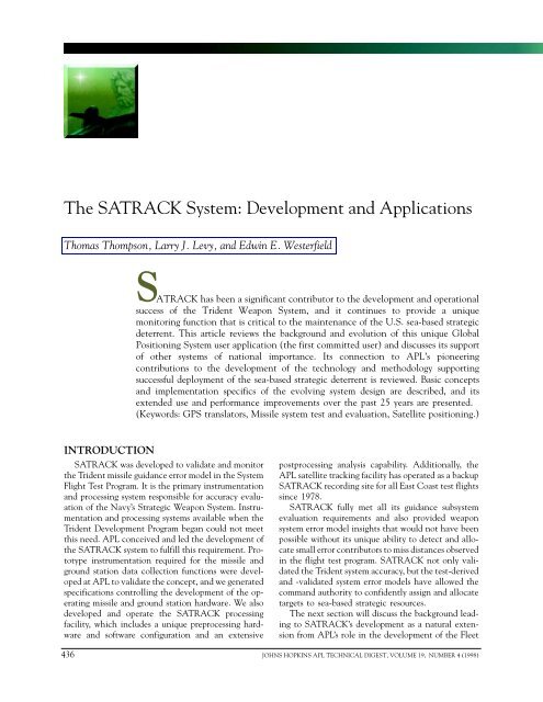
T. THOMPSON, L. J. LEVY, AND E. E. WESTERFIELD<br />
<strong>The</strong> <strong>SATRACK</strong> <strong>System</strong>: <strong>Development</strong> <strong>and</strong> <strong>Applications</strong><br />
Thomas Thompson, Larry J. Levy, <strong>and</strong> Edwin E. Westerfield<br />
<strong>SATRACK</strong><br />
has been a significant contributor to the development <strong>and</strong> operational<br />
success of the Trident Weapon <strong>System</strong>, <strong>and</strong> it continues to provide a unique<br />
monitoring function that is critical to the maintenance of the U.S. sea-based strategic<br />
deterrent. This article reviews the background <strong>and</strong> evolution of this unique Global<br />
Positioning <strong>System</strong> user application (the first committed user) <strong>and</strong> discusses its support<br />
of other systems of national importance. Its connection to APL’s pioneering<br />
contributions to the development of the technology <strong>and</strong> methodology supporting<br />
successful deployment of the sea-based strategic deterrent is reviewed. Basic concepts<br />
<strong>and</strong> implementation specifics of the evolving system design are described, <strong>and</strong> its<br />
extended use <strong>and</strong> performance improvements over the past 25 years are presented.<br />
(Keywords: GPS translators, Missile system test <strong>and</strong> evaluation, Satellite positioning.)<br />
INTRODUCTION<br />
<strong>SATRACK</strong> was developed to validate <strong>and</strong> monitor<br />
the Trident missile guidance error model in the <strong>System</strong><br />
Flight Test Program. It is the primary instrumentation<br />
<strong>and</strong> processing system responsible for accuracy evaluation<br />
of the Navy’s Strategic Weapon <strong>System</strong>. Instrumentation<br />
<strong>and</strong> processing systems available when the<br />
Trident <strong>Development</strong> Program began could not meet<br />
this need. APL conceived <strong>and</strong> led the development of<br />
the <strong>SATRACK</strong> system to fulfill this requirement. Prototype<br />
instrumentation required for the missile <strong>and</strong><br />
ground station data collection functions were developed<br />
at APL to validate the concept, <strong>and</strong> we generated<br />
specifications controlling the development of the operating<br />
missile <strong>and</strong> ground station hardware. We also<br />
developed <strong>and</strong> operate the <strong>SATRACK</strong> processing<br />
facility, which includes a unique preprocessing hardware<br />
<strong>and</strong> software configuration <strong>and</strong> an extensive<br />
postprocessing analysis capability. Additionally, the<br />
APL satellite tracking facility has operated as a backup<br />
<strong>SATRACK</strong> recording site for all East Coast test flights<br />
since 1978.<br />
<strong>SATRACK</strong> fully met all its guidance subsystem<br />
evaluation requirements <strong>and</strong> also provided weapon<br />
system error model insights that would not have been<br />
possible without its unique ability to detect <strong>and</strong> allocate<br />
small error contributors to miss distances observed<br />
in the flight test program. <strong>SATRACK</strong> not only validated<br />
the Trident system accuracy, but the test-derived<br />
<strong>and</strong> -validated system error models have allowed the<br />
comm<strong>and</strong> authority to confidently assign <strong>and</strong> allocate<br />
targets to sea-based strategic resources.<br />
<strong>The</strong> next section will discuss the background leading<br />
to <strong>SATRACK</strong>’s development as a natural extension<br />
from APL’s role in the development of the Fleet<br />
436 JOHNS HOPKINS APL TECHNICAL DIGEST, VOLUME 19, NUMBER 4 (1998)
Ballistic Missile Evaluation <strong>System</strong> <strong>and</strong> the Navy Navigation<br />
Satellite <strong>System</strong> (Transit). <strong>The</strong>n, following a<br />
discussion of the basic concepts, this article will trace<br />
the system’s evolution:<br />
• <strong>SATRACK</strong> I—A technology project to develop <strong>and</strong><br />
demonstrate the instrumentation <strong>and</strong> processing system<br />
using the Trident I missile (1973–1983)<br />
• <strong>SATRACK</strong> II—<strong>The</strong> operational system designed to<br />
meet system requirements for the Trident II missile<br />
(1983–present)<br />
• Other applications—Uses of <strong>SATRACK</strong> for Army<br />
<strong>and</strong> Air Force missile test applications (1983–present)<br />
• <strong>SATRACK</strong> III—Current system upgrade <strong>and</strong> future<br />
applications<br />
BACKGROUND<br />
From 1967 through early 1971, APL conducted a<br />
series of studies to support concept development of the<br />
Defense Navigation Satellite <strong>System</strong> (DNSS). <strong>The</strong>se<br />
studies addressed a variety of configurations capable of<br />
meeting DNSS requirements <strong>and</strong> eventually led to a<br />
concept proposal called Two-In-View (TIV) Transit.<br />
<strong>The</strong> name was chosen to indicate that DNSS requirements<br />
could be met with only two visible satellites (in<br />
contrast to the alternate concepts that required four<br />
visible satellites) <strong>and</strong> that it could evolve naturally<br />
from the already operational Transit system. We chose<br />
this concept because it was the lowest-cost approach<br />
to meeting DNSS requirements.<br />
<strong>The</strong> ability to provide three-dimensional positioning<br />
with the required accuracy using two satellites is<br />
possible only because their motion relative to a user<br />
is significant. <strong>The</strong> alternate concepts were based on<br />
simultaneous range measurements to four satellites.<br />
Since these concepts were not benefited by high<br />
relative motion, they incorporated satellite constellations<br />
at higher altitude. <strong>The</strong> higher-altitude constellations<br />
were selected because they achieved the<br />
required global coverage with a smaller number of<br />
satellites. This choice was partly motivated by the<br />
incorrect assessment that system costs increased as the<br />
required number of satellites increased. However, fewer<br />
satellites were possible because the area that each<br />
served exp<strong>and</strong>ed in direct relation to the reduction in<br />
the number of satellites, <strong>and</strong> costs for signal services<br />
tend to have a direct relationship to service area, not<br />
to the number of satellites. To a first-order approximation,<br />
positioning satellite system costs are independent<br />
of constellation altitude. Further discussion of these<br />
topics <strong>and</strong> the prevalent views of the time is available<br />
from Refs. 1–3.<br />
<strong>The</strong> last performance study of the TIV Transit<br />
system addressed its ability to provide trajectory measurements<br />
of SLBM test flights. <strong>The</strong> study showed that<br />
SLBM measurement objectives could be met, <strong>and</strong> an<br />
THE <strong>SATRACK</strong> SYSTEM<br />
interim report published in late 1971 formulated the<br />
tracking concepts <strong>and</strong> missile <strong>and</strong> ground station capabilities<br />
needed to support TIV Transit measurements<br />
of SLBM flight tests. However, by mid-1972 it was<br />
clear that none of the then-proposed DNSS concepts<br />
would be developed, <strong>and</strong> the missile tracking concept<br />
was temporarily forgotten.<br />
In a parallel chain of events, the Navy’s Strategic<br />
<strong>System</strong>s Programs organization was asked to address<br />
the suitability of the Trident Weapon <strong>System</strong> for more<br />
accurate targeting requirements. Several studies were<br />
initiated to consider this question. <strong>The</strong> primary issues<br />
concerned possible system improvements to achieve<br />
the desired accuracy. An important secondary concern<br />
regarded the method by which the accuracy of the new<br />
system would be validated.<br />
It was soon evident that the impact scoring techniques<br />
used for Polaris <strong>and</strong> Poseidon evaluations would<br />
not be adequate. A new methodology that provided<br />
insights into major error contributors within the flight<br />
test environment would be needed so that accuracy<br />
projections could be based on a high-confidence underst<strong>and</strong>ing<br />
of the underlying system models. <strong>The</strong><br />
technique of comparing observed test impact statistics<br />
with results computed from models used for development<br />
(i.e., “shoot <strong>and</strong> score” approach) was unacceptable.<br />
Assessing performance models in the flight test<br />
environment requires guidance-independent measurements<br />
with sufficient precision to separate out the<br />
important contributors to system inaccuracy. <strong>The</strong><br />
existing range instrumentation (missile tracking <strong>and</strong><br />
trajectory estimation) was largely provided by radar<br />
systems, <strong>and</strong> it was not clear that they could provide<br />
the needed measurement accuracy or coverage in the<br />
broad ocean test areas.<br />
In early 1973, we initiated a study to compare current<br />
range radar with TIV Transit measurement capabilities<br />
in relation to needed SLBM accuracy evaluation<br />
objectives. <strong>The</strong> study results showed that only a<br />
satellite-based measurement system could meet future<br />
requirements. APL presented the <strong>SATRACK</strong> concept<br />
to the Navy’s Strategic <strong>System</strong>s Programs staff in May<br />
1973. <strong>The</strong> proposed system was based on a custom<br />
satellite design patterned after TIV Transit satellites,<br />
but simplified by the removal of any requirement for<br />
real-time positioning service. A six-satellite constellation<br />
would support two flight test windows per day.<br />
<strong>The</strong>se concepts were proposed to minimize costs.<br />
Missile hardware <strong>and</strong> ground support capabilities were<br />
unchanged from the concepts defined in 1971.<br />
<strong>The</strong> proposal was accepted <strong>and</strong> preliminary development<br />
was initiated. However, 1973 was also the year<br />
that the Global Positioning <strong>System</strong> (GPS) development<br />
began. With the emergence of GPS, we were<br />
asked to consider its use in place of the specialized<br />
satellite constellation. Our studies indicated that the<br />
JOHNS HOPKINS APL TECHNICAL DIGEST, VOLUME 19, NUMBER 4 (1998) 437
T. THOMPSON, L. J. LEVY, AND E. E. WESTERFIELD<br />
GPS could be applied to the SLBM accuracy evaluation<br />
system with some changes to the missile <strong>and</strong> ground<br />
station designs. <strong>The</strong>re was a technical concern regarding<br />
the available signal power <strong>and</strong> ionospheric correction<br />
capabilities as well as a programmatic concern<br />
regarding the number of satellites that would be available<br />
for early Trident test flights, but otherwise, the<br />
GPS capabilities were expected to be adequate. In July<br />
1974, the Improved Accuracy Program was initiated to<br />
consider the implications of modifying Trident to support<br />
an improved accuracy requirement. <strong>SATRACK</strong><br />
development was initiated to support the program, <strong>and</strong><br />
in September 1974, DoD Research <strong>and</strong> Engineering<br />
directed the Navy to use GPS for <strong>SATRACK</strong>, making<br />
it the first committed GPS user system.<br />
BASIC CONCEPTS<br />
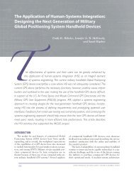
<strong>The</strong> <strong>SATRACK</strong> concept is shown in Fig. 1. Signals<br />
from GPS satellites are relayed by the test missile to<br />
receiving equipment at a launch-area support ship<br />
(LASS) <strong>and</strong> a downrange support site (DRSS). At the<br />
L-b<strong>and</strong><br />
low noise<br />
amplifier<br />
Missile<br />
Translator<br />
Telemetry<br />
Station<br />
All-in-view GPS satellites<br />
(L-b<strong>and</strong> signals)<br />
M1<br />
First IF <strong>and</strong><br />
GPS<br />
signal filter<br />
Oscillator <strong>and</strong><br />
frequency<br />
synthesizer<br />
Recording<br />
equipment<br />
Figure 1. <strong>SATRACK</strong> measurement concept. Signals transmitted from the Global Positioning<br />
<strong>System</strong> satellites are received at the missile, translated to another frequency, <strong>and</strong><br />
relayed to the telemetry station, where they are recorded for later playback <strong>and</strong><br />
postprocessing at APL.<br />
M2<br />
(Signal<br />
data)<br />
beginning of the Trident Flight Test Program a ship was<br />
used for downrange support; now that support is provided<br />
by a l<strong>and</strong> station. <strong>The</strong> missile hardware was<br />
called a translator to emphasize that no signal tracking<br />
functions are accomplished in the missile (i.e., the<br />
signals are simply “translated” to S-b<strong>and</strong> <strong>and</strong> retransmitted).<br />
<strong>The</strong> evolution of translator systems is discussed<br />
in a companion article by Thompson <strong>and</strong><br />
Westerfield elsewhere in this issue. <strong>The</strong> receiving<br />
equipment at the LASS <strong>and</strong> DRSS also does not provide<br />
a <strong>SATRACK</strong> signal tracking function (although<br />
the DRSS does provide a lower-accuracy real-time<br />
tracking capability to support range safety). <strong>The</strong> translated<br />
signals received at both sites are sampled at a<br />
high enough rate to capture the desired signal spectrum.<br />
Precision tracking of the GPS signals is actually<br />
accomplished at the APL postflight tracking facility<br />
through playback of the recorded translator signals.<br />
After the signal tracking data are recovered <strong>and</strong><br />
several systematic corrections are applied, the derived<br />
satellite-to-missile (link) range <strong>and</strong> integrated Doppler<br />
data are used in a large Kalman filter that provides<br />
estimates of trajectory-observable<br />
model parameters (this terminology<br />
is used because not all model<br />
parameters produce observable signatures<br />
in any specific trajectory<br />
geometry). <strong>The</strong> processing methodology<br />
developed at APL properly<br />
combines a priori model data <strong>and</strong><br />
trajectory-observable model data<br />
for each flight test.<br />
Significantly, the critical mea-<br />
(S-b<strong>and</strong> signals)<br />
S-b<strong>and</strong><br />
power<br />
amplifier<br />
APL<br />
postprocessing<br />
facility<br />
surements are provided by carrier<br />
phase tracking of the GPS-tomissile<br />
signals. <strong>The</strong> GPS signal<br />
phase measurements (i.e., integrated<br />
Doppler) sense range changes<br />
along each signal line of sight to a<br />
small fraction of a wavelength (i.e.,<br />
a few millimeters). <strong>The</strong>se measurements,<br />
which are compared with<br />
their values computed from guidance<br />
sensor data <strong>and</strong> satellite<br />
position <strong>and</strong> velocity estimates,<br />
provide most of the information.<br />
Range measurement noise in the<br />
recovered GPS range-code signals<br />
is of secondary importance. In<br />
essence, the inertial sensors provide<br />
high-frequency motion information<br />
better than the signal processes,<br />
the Doppler information<br />
senses the systematic errors associated<br />
with the inertial sensors, <strong>and</strong><br />
the range data provide an initial<br />
438 JOHNS HOPKINS APL TECHNICAL DIGEST, VOLUME 19, NUMBER 4 (1998)
condition for all the dynamic measurements. <strong>The</strong>refore,<br />
range noise (i.e., noise in the range tracking<br />
loops) can be smoothed over the full flight interval.<br />
<strong>The</strong> range noise remaining after this process is smaller<br />
than other bias-like uncertainties that set the limit on<br />
absolute position accuracy (e.g., satellite position).<br />
<strong>The</strong> <strong>SATRACK</strong> system configuration is shown in<br />
Fig. 2. Signals transmitted by GPS satellites are tracked<br />
by the GPS tracking network for several days surrounding<br />
the missile test flight. <strong>The</strong> tracking data from this<br />
operation are processed to derive satellite ephemerides<br />
<strong>and</strong> clock estimates that have the highest possible<br />
accuracy during the missile flight interval. <strong>The</strong> ephemerides<br />
<strong>and</strong> clock estimates are used by the postflight<br />
receiver <strong>and</strong> missile processor to provide the SA-<br />
TRACK data products for each flight.<br />
During the missile flight, all in-view GPS satellite<br />
signals are received at the missile, translated to S-b<strong>and</strong>,<br />
<strong>and</strong> retransmitted to the surface station. <strong>The</strong> translated<br />
GPS signals are recovered with the same station<br />
tracking antenna used for all the missile telemetry<br />
signals. <strong>The</strong> translated GPS signal data are separated<br />
into range safety <strong>and</strong> accuracy operations. <strong>The</strong> range<br />
safety function processes the lower-accuracy GPS signals<br />
to provide a real-time tracking solution for the<br />
range comm<strong>and</strong>. <strong>The</strong> real-time accuracy function is<br />
provided by simply sampling <strong>and</strong> recording the GPS<br />
signals (i.e., by sampling the signals at a rate that<br />
GPS<br />
satellites<br />
Range<br />
safety<br />
system<br />
Test<br />
missile<br />
Tracking<br />
antenna<br />
THE <strong>SATRACK</strong> SYSTEM<br />
captures the full b<strong>and</strong>width of the selected range-code<br />
modulation).<br />
<strong>The</strong> telemetry data are also recorded for postflight<br />
analysis. <strong>The</strong>se data, along with GPS ephemeris <strong>and</strong><br />
clock data, are used to provide tracking aids for the<br />
postflight receiver <strong>and</strong> measurement estimates for the<br />
missile processor. Raw tracking data from the postflight<br />
receiver are corrected for known systematic errors<br />
(e.g., antenna lever arm) before being passed to the<br />
missile processor. <strong>The</strong> missile processor is a large<br />
Kalman filter that operates on the raw guidance sensor<br />
measurement data supplied by missile telemetry. With<br />
these data <strong>and</strong> satellite ephemeris <strong>and</strong> clock estimates,<br />
the processor computes the expected satellite measurement<br />
data. <strong>The</strong>se expected data are compared to the<br />
actual satellite measurements, <strong>and</strong> the observed differences<br />
are used to drive the filter model to a best estimate<br />
of the underlying guidance model errors.<br />
Assuming that the data processing has not identified<br />
a system fault (i.e., an error component well outside its<br />
expected performance), the processed data from each<br />
flight test are used to provide estimates of major contributors<br />
to impact miss. Figure 3 shows a hypothetical<br />
diagram used to allocate contributions to impact miss.<br />
<strong>The</strong> method is based on projecting each error contributor<br />
<strong>and</strong> its uncertainty into the impact domain. <strong>The</strong><br />
first-level allocation is at the subsystem level (initial<br />
conditions, guidance, <strong>and</strong> deployment <strong>and</strong> reentry); a<br />
Real time Postflight<br />
Translator<br />
receiver<br />
<strong>SATRACK</strong><br />
recorder<br />
GPS<br />
tracking<br />
network<br />
Preamplifier<br />
Telemetry<br />
receiver<br />
Translator<br />
recorder<br />
Orbit/clock<br />
determination<br />
facility<br />
Postflight<br />
receiver<br />
Telemetry<br />
processor<br />
Ephemeris<br />
<strong>and</strong> clock<br />
estimates<br />
Tracker<br />
corrections<br />
Missile<br />
processor<br />
Guidance data<br />
Estimated initial<br />
conditions<br />
<strong>System</strong><br />
models<br />
Figure 2. Basic <strong>SATRACK</strong> configuration. For a number of days surrounding the missile flight, GPS signals are received, tracked, <strong>and</strong><br />
recorded at the GPS tracking sites. During the missile flight, GPS signals are received by the missile, translated in frequency, <strong>and</strong><br />
transmitted to the surface station(s). A tracking antenna at the station receives the missile signals, separates the various components,<br />
<strong>and</strong> records the data. <strong>The</strong> postflight process uses the recorded data to give satellite ephemerides <strong>and</strong> clock estimates, tracked signal<br />
data from the postflight receiver, <strong>and</strong> missile guidance sensor data. After the signal tracking data are corrected, all the data elements<br />
<strong>and</strong> the system models are used by the missile processor to produce the flight test data products.<br />
JOHNS HOPKINS APL TECHNICAL DIGEST, VOLUME 19, NUMBER 4 (1998) 439
T. THOMPSON, L. J. LEVY, AND E. E. WESTERFIELD<br />
Uncertainty in<br />
initial conditions<br />
estimate<br />
Gyros<br />
Uncertainty<br />
in guidance<br />
estimate<br />
Accelerometers<br />
Guidance<br />
Total<br />
<strong>SATRACK</strong><br />
uncertainty<br />
Total <strong>SATRACK</strong><br />
Deployment<br />
<strong>and</strong> reentry<br />
Orientation<br />
Initial<br />
conditions<br />
Downrange miss<br />
Position<br />
Velocity<br />
second level provides data for major error groups within<br />
each subsystem (e.g., accelerometers). A third level,<br />
not shown in the figure, produces estimates of fundamental<br />
error terms of the guidance model (e.g., an<br />
accelerometer scale factor error). In addition, SA-<br />
TRACK provides a point estimate of the initial conditions<br />
<strong>and</strong> a pre-deployment estimate; however, its<br />
principal purpose is to evaluate guidance subsystem<br />
error. <strong>The</strong> results from each flight are checked for statistical<br />
consistency with independent measures of impact,<br />
initial conditions, <strong>and</strong> several other factors.<br />
As noted previously, limitations of test geometry<br />
will prohibit observations of all errors in any single<br />
flight test. However, since each flight provides observations<br />
of the underlying missile guidance error models,<br />
the data from many flight tests can be combined.<br />
<strong>The</strong> final cumulative analysis of flight test data produces<br />
a guidance error model for the Trident Weapon<br />
<strong>System</strong>. It combines observations from each flight to<br />
derive a tactically representative missile guidance<br />
model based completely on flight test data. This model<br />
is used with other similarly derived subsystem models<br />
to develop planning factors used to assign weapon<br />
system targets.<br />
<strong>SATRACK</strong> has evolved over a quarter century. <strong>The</strong><br />
original development for the Trident I missile (C4)<br />
began in earnest in 1974. 4 <strong>The</strong> C4 version (<strong>SATRACK</strong><br />
I) was a technology development program aimed at<br />
“Observed” impact<br />
Crossrange miss<br />
Impact<br />
uncertainties<br />
Estimated<br />
<strong>SATRACK</strong><br />
impact<br />
Figure 3. Hypothetical example of <strong>SATRACK</strong> impact evaluation. Each error estimate<br />
provided by the <strong>SATRACK</strong> process is projected into the impact domain, showing its<br />
downrange <strong>and</strong> crossrange contribution to impact miss (the center of the coordinate<br />
system is the aim point). Uncertainties for each estimate are also projected. <strong>The</strong> estimated<br />
errors <strong>and</strong> their uncertainties are tested for statistical consistency with system models <strong>and</strong><br />
other independently measured results (e.g., the initial conditions derived from launch area<br />
instrumentation).<br />
(1) gaining insight into what<br />
was needed for improved accuracy<br />
<strong>and</strong> (2) developing an adequate<br />
accuracy evaluation system. SA-<br />
TRACK, as it evolved, is the fulfillment<br />
of the second major objective.<br />
<strong>SATRACK</strong> I proved that<br />
it could provide adequate estimates<br />
of guidance subsystem errors<br />
for individual flights. It was a pioneering<br />
effort in that both the<br />
tracking methods <strong>and</strong> the large<br />
Kalman filter processing techniques<br />
were pushing the state-ofthe-art.<br />
<strong>The</strong> second phase (<strong>SATRACK</strong><br />
II) was a major upgrade in response<br />
to the stringent measurement requirements<br />
set by the Accuracy<br />
Evaluation <strong>System</strong> study. 5 <strong>The</strong><br />
study established the total weapon<br />
system instrumentation requirements<br />
for the Trident II (D5) missile<br />
in accordance with specified<br />
accuracy evaluation objectives,<br />
including <strong>SATRACK</strong> as well as<br />
other prelaunch, in-flight, <strong>and</strong><br />
reentry area instrumentation. SA-<br />
TRACK II has been operational since 1987.<br />
A general upgrade has been initiated to replace<br />
aging components of the D5 test system. <strong>The</strong> new<br />
<strong>SATRACK</strong> ground recording equipment is currently<br />
in the final stages of checkout, upgrading at the postflight<br />
facility is well along, <strong>and</strong> preliminary design of<br />
replacement missile test components is beginning. Furthermore,<br />
efforts have been focused for the last several<br />
years on a new GPS translator system to support Trident<br />
reentry body testing. <strong>The</strong> upgraded system will<br />
not only modernize the facility hardware <strong>and</strong> software<br />
functions, it will also substantially extend <strong>SATRACK</strong><br />
performance capabilities.<br />
<strong>SATRACK</strong> EVOLUTION<br />
<strong>SATRACK</strong> I<br />
<strong>The</strong> C4 missile design was well under way before it<br />
was decided to implement the <strong>SATRACK</strong> system. <strong>The</strong><br />
proposed design approach did minimize the required<br />
additional missile electronics <strong>and</strong> it did take advantage<br />
of the existing S-b<strong>and</strong> antenna; however, a new GPS<br />
antenna had to be added. <strong>The</strong> C4 design constraints<br />
held the GPS antenna configuration to four elements<br />
spaced uniformly around the missile circumference.<br />
With the wide spacing between antenna elements,<br />
signal sums would cause strong interferometer null<br />
440 JOHNS HOPKINS APL TECHNICAL DIGEST, VOLUME 19, NUMBER 4 (1998)
patterns. To minimize the problems associated with<br />
removing antenna phase effects in the postprocessor,<br />
opposite pairs of antennas were summed to form twoelement<br />
interferometers oriented 90° from each other.<br />
<strong>The</strong> translator input was time multiplexed between<br />
the two interferometers. <strong>The</strong> time multiplex rate was<br />
set high enough to be outside the b<strong>and</strong>width of the<br />
signal tracking loops so that both inputs could be<br />
tracked simultaneously when the signals were strong<br />
enough. However, the tracking data used by the system’s<br />
Kalman filter were selected to include only tracking<br />
data from the regions of each antenna where the<br />
phase effects were well understood (i.e., away from the<br />
null regions). Although this was a reasonable compromise<br />
within the set constraints, it led to an antenna<br />
design with a very poor gain over a large region (i.e.,<br />
the specified gain was more than 14 dB below an ideal<br />
isotropic antenna, 0 dBi, over 15% of the coverage<br />
region). This poor gain, coupled with the levels of GPS<br />
satellite signals, represented a challenging condition<br />
for signal tracking.<br />
Signal refraction through the ionosphere at the<br />
GPS prime frequency (L 1 = 1575.42 MHz) is significant,<br />
<strong>and</strong> it must be corrected for precision positioning<br />
applications. GPS provides a second frequency signal<br />
(L 2 = 1227.60 MHz) that is used with the prime frequency<br />
to compute the needed correction for signal<br />
refraction. Modulations applied to each frequency<br />
provide the basis for epoch measurements used to<br />
determine the distance to each satellite (range measurements).<br />
Two range-code modulations are applied<br />
to the L 1 frequency, one having a 2-MHz b<strong>and</strong>width<br />
<strong>and</strong> a second having a 20-MHz b<strong>and</strong>width. <strong>The</strong> L 2<br />
frequency, however, is modulated only with the 20-<br />
MHz b<strong>and</strong>width ranging code.<br />
<strong>The</strong> strongest GPS signal is the narrow-b<strong>and</strong>width<br />
L 1 signal; the L 2 signal is at one-fourth the power level<br />
of the L 1 signal. <strong>The</strong> wide b<strong>and</strong>width <strong>and</strong> lower power<br />
characteristics of the L 2 signal, combined with the<br />
antenna constraints for C4, precluded its use in the<br />
<strong>SATRACK</strong> I system. <strong>The</strong>rfore, the C4 translator was<br />
designed to use only the narrow-b<strong>and</strong>width GPS signal.<br />
<strong>The</strong> narrow b<strong>and</strong>width code signal is referred to<br />
as the clear/acquisition (C/A) code, <strong>and</strong> the wideb<strong>and</strong>width<br />
code is normally referred to as the protected<br />
or precision (P) code. Sometimes the P code is called<br />
the P/Y code to indicate that the P code is encrypted.<br />
Since the C4 translator would be using only the<br />
GPS L 1 C/A signal, another means was needed to<br />
correct for ionospheric refraction. Because of our development<br />
of <strong>and</strong> operational experience with Transit,<br />
we had an extensive background in ionospheric science.<br />
We had developed <strong>and</strong> evaluated models of the<br />
ionosphere, <strong>and</strong> we understood their limitations. We<br />
therefore decided to provide a ground-based satellitelike<br />
transmitter (i.e., a pseudosatellite) with two<br />
THE <strong>SATRACK</strong> SYSTEM<br />
frequencies. Measurements of these two signals yielded<br />
a measure of refraction along the signal path between<br />
the missile <strong>and</strong> the pseudosatellite. <strong>The</strong>se data gave an<br />
estimate of the electron density profile in the region<br />
of the missile flight path. <strong>The</strong> profile was then used to<br />
adjust our best available ionosphere model, which was<br />
then applied to estimate the refraction correction for<br />
each GPS satellite-to-missile L 1 signal path. <strong>The</strong> primary<br />
pseudosatellite signal is similar to the GPS L 1<br />
signal. <strong>The</strong> second pseudosatellite signal was set at<br />
one-fourth the L 1 signal frequency (the L 1/4 signal),<br />
<strong>and</strong> it was modulated with a 200-KHz b<strong>and</strong>width ranging<br />
code. Another natural use of the L 1/4 signal was<br />
for SLBM range safety. By adding extra L 1/4 pseudosatellites<br />
at selected range sites, the required (loweraccuracy)<br />
real-time trajectory measurement is determined<br />
in relation to the three or more pseudosatellite<br />
locations. This range safety system was qualified during<br />
early C4 flights, which were equipped with both translators<br />
<strong>and</strong> C-b<strong>and</strong> radar transponders. (Although the<br />
range safety system shares components with SA-<br />
TRACK, it is normally treated as a separate system <strong>and</strong><br />
we will not discuss it further.)<br />
<strong>The</strong> Laboratory provided overall technical direction<br />
for the <strong>SATRACK</strong> system <strong>and</strong> developed <strong>and</strong><br />
continues to operate the unique postflight processing<br />
subsystem. Missile hardware development was part of<br />
the Navy’s missile development contract with Lockheed<br />
Missiles <strong>and</strong> Space Company, <strong>and</strong> the ground<br />
recording <strong>and</strong> range safety equipment development<br />
was added to the Navy’s contract with Interstate Electronics<br />
Corporation.<br />
Another major challenge in <strong>SATRACK</strong> development<br />
was implementation of the large Kalman filter<br />
processing technique. To get a head start on developing<br />
the required C4 postflight processing software, the<br />
proposed methodology was applied to radar data collected<br />
for Poseidon (C3) missile flight tests. We recognized<br />
from the outset that the radar data would be<br />
inadequate because of shortfalls in system geometry<br />
<strong>and</strong> velocity measurement accuracy; however, valuable<br />
analysis insights <strong>and</strong> practical experience would be<br />
gained in the process. <strong>The</strong> C3 processing would be<br />
applied to data available from selected earlier Demonstration<br />
<strong>and</strong> Shakedown Operation (DASO) flight<br />
tests <strong>and</strong> all subsequent C3 DASOs (after March<br />
1975) until the beginning of the C4 Missile Flight Test<br />
Program. DASOs were selected because the radar geometry<br />
was very weak in the operational test area.<br />
An improved tracking capability was subsequently<br />
added to collect Doppler data from missile telemetry<br />
signals to supplement the radar data. This capability,<br />
called the Telemetry Doppler Metric Measurement<br />
<strong>System</strong> (TDMMS), was based on the use of telemetry<br />
signal Doppler differences as observed at multiple receiving<br />
sites. <strong>The</strong> hardware to record these data for<br />
JOHNS HOPKINS APL TECHNICAL DIGEST, VOLUME 19, NUMBER 4 (1998) 441
T. THOMPSON, L. J. LEVY, AND E. E. WESTERFIELD<br />
postflight processing was in place to support two C3<br />
DASO tests <strong>and</strong> C4 tests beginning with C4X-13.<br />
(<strong>The</strong> “X” flight designation applies to developmental<br />
flight tests conducted from a launch pad.) In all, six<br />
C3 radar, two C3 radar/TDMMS, two C4X radar, six<br />
C4X radar/TDMMS, six C4-PEM (Production Evaluation<br />
Missile) radar/TDMMS, <strong>and</strong> three C4-DASO<br />
radar/TDMMS flight tests were processed with the<br />
modified <strong>SATRACK</strong> postflight processing software.<br />
<strong>The</strong> last three C4X flights <strong>and</strong> all the C4-PEM/DASO<br />
flights processed with the radar/TDMMS system were<br />
also processed with the GPS/<strong>SATRACK</strong> system.<br />
TDMMS processing was improved on C4 flights beyond<br />
C4X-19 by using a translator signal, known as the<br />
pilot carrier, for the Doppler measurement rather than<br />
the telemetry signal.<br />
<strong>The</strong> overlap of radar/TDMMS <strong>and</strong> GPS measurements<br />
was extended to overcome the limited number<br />
of GPS satellites available through the early C4 tests;<br />
it also provided an opportunity to compare the GPS<br />
processing results with radar <strong>and</strong> radar/TDMMS results.<br />
In these early C4 tests, the final best estimates<br />
of missile system performance were derived from a<br />
process that combined the data from all available<br />
methods. However, once the satellite support reached<br />
the expected levels, its accuracy was sufficiently superior<br />
to the radar/TDMMS that there was no longer any<br />
benefit from the combining process. Radar/TDMMS<br />
processing yielded only a part of the total validation<br />
activity associated with <strong>SATRACK</strong> development.<br />
It is easy now to forget how much of this technology<br />
was yet to be proven when <strong>SATRACK</strong> development<br />
started. GPS was in a concept demonstration phase,<br />
the missile translator <strong>and</strong> digital postflight tracking<br />
capabilities were untested, <strong>and</strong> the Kalman filter processing<br />
techniques were being extended significantly<br />
beyond the existing state-of-the-art. <strong>The</strong> <strong>SATRACK</strong><br />
<strong>Development</strong> Program included a substantial effort to<br />
validate all aspects of its accuracy (i.e., we had to<br />
validate the validation system). 6 In addition to the<br />
radar/TDMMS work, <strong>SATRACK</strong> accuracy was validated<br />
with a comprehensive simulation system <strong>and</strong> the<br />
use of a unique <strong>SATRACK</strong> test satellite.<br />
A hardware-in-the-loop simulation facility was<br />
developed that produced simulated data inputs for all<br />
the major processing elements of the system from<br />
software simulations of GPS satellite motions <strong>and</strong> a<br />
test missile flight trajectory. <strong>The</strong> software simulation<br />
produced GPS satellite tracking data files, including<br />
simulated errors, as if they were provided by the GPS<br />
tracking facilities. <strong>The</strong>se simulated data were sent to<br />
the Naval Surface Warfare Center (NSWC) for processing<br />
(using prototype software being developed<br />
for <strong>SATRACK</strong> operation). NSWC then produced satellite<br />
position <strong>and</strong> velocity estimates (i.e., ephemerides)<br />
<strong>and</strong> clock files that were returned to the APL<br />
postprocessing facility. <strong>The</strong> missile flight simulation<br />
produced simulated telemetry guidance data, including<br />
errors, <strong>and</strong> these were also forwarded to the postprocessing<br />
facility.<br />
<strong>The</strong> missile <strong>and</strong> satellite trajectories, including simulated<br />
errors for satellite positions <strong>and</strong> clocks, were<br />
also used to drive satellite signal generators to produce<br />
simulated GPS signals. <strong>The</strong>se, in turn, were passed<br />
through digitally controlled phase shifters <strong>and</strong> a time<br />
multiplexing switch to emulate the missile GPS antenna<br />
network. This antenna network simulator was connected<br />
to a missile translator hardware simulator that<br />
produced the translated GPS signals at S-b<strong>and</strong>. An Sb<strong>and</strong><br />
antenna hardware simulator produced the outputs,<br />
which were recorded by prototype telemetry station<br />
receiver <strong>and</strong> recording equipment. <strong>The</strong> hardware<br />
simulator drivers were conditioned to encompass all<br />
anticipated effects, including signal propagation<br />
through the ionosphere <strong>and</strong> troposphere. <strong>The</strong> recorded<br />
data produced by this simulation capability were<br />
equivalent to the data that would be received from a<br />
telemetry site. <strong>The</strong>se data, too, were sent to the postprocessing<br />
facility.<br />
<strong>The</strong> postprocessing facility now had all the inputs<br />
expected for an actual flight test: GPS ephemerides<br />
<strong>and</strong> clock files from NSWC, telemetry data, <strong>and</strong> the<br />
translated signal data tape. <strong>The</strong> facility then processed<br />
these data as if they had come from an actual flight<br />
test <strong>and</strong> produced an estimate of the underlying model<br />
errors that could be compared to the model errors used<br />
to produce the simulated data. <strong>The</strong> process provided<br />
a complete test of the processing system to the extent<br />
that the simulations were valid representations of the<br />
real world. Segments of the simulation capability were<br />
used in many test support activities associated with<br />
developing the processing hardware <strong>and</strong> software at<br />
the postprocessing facility. Two complete formal runs<br />
of the simulator were used to conclude this element of<br />
the <strong>SATRACK</strong> system validation.<br />
A second very important test <strong>and</strong> validation element,<br />
conceived by the APL <strong>SATRACK</strong> design team,<br />
was based on tracking a satellite configured to act like<br />
a C4 missile in its coast phase. Transat was produced<br />
by modifying a Transit satellite that was in st<strong>and</strong>by<br />
storage at APL. <strong>The</strong> modifications included the addition<br />
of a structural extension that comprised a C4<br />
translator prototype (actually two for redundancy) <strong>and</strong><br />
an antenna array that matched the performance characteristics<br />
of the C4 configuration. Once in orbit,<br />
Transat provided regularly available missile-like test<br />
opportunities for <strong>SATRACK</strong> system <strong>and</strong> hardware validation<br />
tests. Transit navigation system capabilities<br />
were maintained in Transat so that it could serve as<br />
an additional operational navigation satellite when it<br />
was not being used for <strong>SATRACK</strong> test purposes. <strong>The</strong><br />
Transit capabilities were also the basis for independent<br />
442 JOHNS HOPKINS APL TECHNICAL DIGEST, VOLUME 19, NUMBER 4 (1998)
satellite trajectory measurements that could be compared<br />
with translator-derived trajectory measurements<br />
for validation purposes.<br />
Transat was launched in October 1977 before any<br />
GPS satellites were available. In early November, the<br />
satellite was checked out in the Transit mode to verify<br />
that it was ready to support operational navigation<br />
users. It was then switched to the Transat mode, <strong>and</strong><br />
initial tests were conducted with the APL pseudosatellite.<br />
Through May 1978, Transat was primarily used<br />
to test equipment at the eastern <strong>and</strong> western test ranges.<br />
<strong>The</strong>se tests provided the capability to check real<br />
system data interfaces using pseudosatellite signals<br />
with an emphasis on range safety system testing. Transat<br />
also proved to be an effective tool for checkout of<br />
the TDMMS. However, validation of GPS tracking<br />
concepts would have to wait until at least two satellites<br />
were available.<br />
In June 1978, the first missile translator flight test,<br />
C4X-17, occurred. Only one GPS satellite was available<br />
for this test, <strong>and</strong> the translator failed after a short<br />
period of operation. However, the test was significant<br />
to the <strong>SATRACK</strong> developers because it was the first<br />
time that we were able to demonstrate that actual<br />
translated GPS signals could be successfully tracked at<br />
the APL postflight tracking facility using data recorded<br />
by one of the range telemetry sites. <strong>The</strong> C4X-18 flight<br />
test in August 1978 was supported by two GPS satellites,<br />
<strong>and</strong> the missile translator worked perfectly<br />
throughout the flight. Since then, translators have<br />
performed successfully on all flight tests. This test<br />
provided the first opportunity to complete a full missile<br />
evaluation with <strong>SATRACK</strong> <strong>and</strong> initiated the first<br />
opportunities for Transat evaluations of the GPS<br />
capabilities.<br />
<strong>The</strong> <strong>SATRACK</strong> processing facility was now operating<br />
at an intense level. Transat validation activities<br />
were just getting started, radar/TDMMS C4 processing<br />
was continuing, normal <strong>SATRACK</strong> C4 processing was<br />
beginning, system validation runs were concluding,<br />
<strong>and</strong> we were first beginning to evaluate the actual<br />
ephemeris accuracy for GPS satellites. <strong>The</strong> original<br />
estimates for these errors reflected into range <strong>and</strong> range<br />
rate uncertainties for each satellite line of sight were<br />
12 ft <strong>and</strong> 0.005 ft/s, respectively.<br />
To directly assess the value of these errors during<br />
each Transat or missile flight test period, data were<br />
collected at an accurately surveyed location. We referred<br />
to this data collecting as “static missile tests.”<br />
<strong>The</strong>se tests provided a direct observation of the link<br />
range <strong>and</strong> range rate errors relative to those computed<br />
from the satellite ephemeris. <strong>The</strong> formal simulation<br />
validation runs were completed in January 1979, <strong>and</strong><br />
a four-satellite Transat validation test was conducted<br />
in March 1979. That Transat test <strong>and</strong> the static missile<br />
results indicated that the GPS ephemeris was not<br />
THE <strong>SATRACK</strong> SYSTEM<br />
providing the expected accuracy. In the early days, we<br />
cross-checked ephemeris data from NSWC with data<br />
from the GPS Master Control Station (the official<br />
system source) <strong>and</strong> with data provided by Aerospace<br />
Corporation. A careful analysis of all the available data<br />
indicated that the GPS ephemeris errors were about 3<br />
times larger than expected for the period covering<br />
C4X-18 (two GPS satellites), C4X-19 (three GPS<br />
satellites), <strong>and</strong> C4X-21 (four GPS satellites) flight<br />
tests. 7 <strong>The</strong> limited number of satellites <strong>and</strong> the largerthan-expected<br />
ephemeris errors were the major difficulties;<br />
all other aspects of the system performed as<br />
expected.<br />
<strong>The</strong> process of evaluating sources of ephemeris<br />
errors continued through the end of 1981; 8 to 10<br />
different software configurations were evaluated.<br />
While this evaluation was being conducted, the initial<br />
baseline ephemeris generation software was being<br />
maintained through all flight tests to that time. However,<br />
in January 1982, a new baseline was selected that<br />
produced an improvement of about a factor of 2. To<br />
maintain consistent processing results, all previously<br />
processed C4 DASO <strong>and</strong> operational test flights<br />
(about 20) were reprocessed with the new baseline<br />
ephemeris generation software. On the basis of the<br />
limitations of the early C4X flight tests, <strong>SATRACK</strong><br />
processing results were compared to radar/TDMMS<br />
results into the early operational tests. 8 After the baseline<br />
was adjusted, C4 trajectory accuracy achieved<br />
with the <strong>SATRACK</strong> I system, based on the first 31<br />
DASO <strong>and</strong> operational flight tests, had a position<br />
uncertainty of 35 ft <strong>and</strong> a velocity uncertainty of 0.09<br />
ft/s at body deployment. 9<br />
Some finer-grain improvements in ephemeris were<br />
subsequently achieved by adding an additional GPS<br />
data collection site at APL, <strong>and</strong> Transat supported<br />
range safety testing as late as May 1982. For the most<br />
part, the <strong>SATRACK</strong> I project was complete, although<br />
translators continue to support all C4 flight tests. In<br />
all, translators have successfully supported range safety<br />
<strong>and</strong> accuracy processing requirements for 154 C4 flight<br />
tests through the end of 1997.<br />
<strong>SATRACK</strong> II<br />
<strong>The</strong> development of the Trident II (D5) missile<br />
began in 1981. To support this development, APL<br />
conducted the Accuracy Evaluation <strong>System</strong> study.<br />
That study supported development of the technical<br />
objectives <strong>and</strong> guidelines document that defined the<br />
accuracy evaluation requirements for the D5 Missile<br />
Flight Test Program. <strong>The</strong> <strong>SATRACK</strong> II requirements,<br />
defined by the Accuracy Evaluation <strong>System</strong> study,<br />
included significant performance enhancements.<br />
It was clear that the D5 requirements could not<br />
be met without a dual-frequency GPS signal tracking<br />
JOHNS HOPKINS APL TECHNICAL DIGEST, VOLUME 19, NUMBER 4 (1998) 443
T. THOMPSON, L. J. LEVY, AND E. E. WESTERFIELD<br />
capability to permit ionospheric corrections. <strong>The</strong> GPS<br />
signal structures were reviewed in a series of meetings<br />
with the GPS joint program staff. Unlike the L 1 signal,<br />
the L 2 signal could only be modulated by either the<br />
narrowb<strong>and</strong> C/A code or the wideb<strong>and</strong> P code. <strong>The</strong><br />
possibility of temporarily switching to the C/A code<br />
modulation on L 2 to support Trident tests was considered<br />
impractical because of the effect on other users.<br />
Future satellites might have been modified to include<br />
the dual-code capability on both frequencies. However,<br />
the joint program staff suggested an alternative that<br />
would use a third GPS frequency (L 3). This transmission<br />
served a nonpositioning purpose. It was used only<br />
intermittently, it was derived from the same frequency<br />
source as the positioning signals, <strong>and</strong> it could have the<br />
C/A code modulation applied when needed for<br />
Trident test support. This approach was agreed to, <strong>and</strong><br />
it became the baseline GPS signal concept for<br />
<strong>SATRACK</strong> II.<br />
<strong>The</strong> implementation of a dual-frequency GPS capability<br />
naturally affected all other aspects of the system<br />
hardware configuration. <strong>The</strong> addition of another<br />
signal channel to the missile translator could increase<br />
the output b<strong>and</strong>width requirement <strong>and</strong> affect the telemetry<br />
station recording requirement. However, we<br />
recognized that the two GPS signals could be overlaid<br />
in a common translator channel. <strong>The</strong> signals could be<br />
separated during the signal tracking operation by virtue<br />
of the differences in their code structures, but at<br />
the expense of increased noise in each signal. Another<br />
benefit of the overlay was that the <strong>SATRACK</strong> I recorder<br />
would not need modification. We also realized<br />
that the range safety tracking capability could be based<br />
on the translated GPS signals, that is, this choice<br />
would eliminate the need for the L 1/4 translated signal<br />
channel. <strong>The</strong> initial system design was based on the<br />
common channel GPS approach, which we tested at<br />
APL. However, at the completion of the preliminary<br />
design phase, the <strong>SATRACK</strong> II baseline was established<br />
with a separate channel L 1/L 3 configuration, <strong>and</strong><br />
the range safety system was based on the GPS<br />
L 1 C/A signal alone.<br />
Another major effort in establishing the SA-<br />
TRACK II baseline concerned the missile antenna<br />
configuration. A careful study of the phase noise characteristics<br />
of several c<strong>and</strong>idate configurations eventually<br />
led to the choice of a wraparound antenna array.<br />
This design was selected because it minimized phase<br />
variations in the missile roll plane, apart from small<br />
angular regions in the nose <strong>and</strong> tail directions. This<br />
choice was also important to the range safety configuration,<br />
not because of accuracy considerations but<br />
because it allowed for smoother, more continuous<br />
performance of the real-time signal tracking loops.<br />
<strong>The</strong>se were important but relatively straightforward<br />
upgrades to the <strong>SATRACK</strong> I system. All the missile<br />
<strong>and</strong> telemetry station hardware requirements were<br />
updated to include the modifications, <strong>and</strong> the APL<br />
simulation facility was updated to support development<br />
of the postprocessing facilities. <strong>The</strong> development<br />
of the upgraded postprocessing facility was then begun.<br />
<strong>The</strong> new missile hardware test equipment configuration<br />
was again provided within the Lockheed Missiles<br />
<strong>and</strong> Space Company development contract, <strong>and</strong> the<br />
telemetry station upgrades were provided within the<br />
Interstate Electronics Corporation contract.<br />
<strong>The</strong> major hardware development effort at APL<br />
focused on a redesigned <strong>SATRACK</strong> postflight tracking<br />
configuration to enhance accuracy <strong>and</strong> throughput.<br />
<strong>The</strong> tracking system was upgraded to track 12 dualfrequency<br />
links from right- <strong>and</strong> left-h<strong>and</strong> circularly<br />
polarized translated signals (i.e., 48 range-code <strong>and</strong><br />
carrier tracking loops). Similarly, the tracked data correction<br />
<strong>and</strong> editing software was enhanced to include<br />
automatic editing <strong>and</strong> analyst-interactive capabilities.<br />
<strong>The</strong> postflight tracking software was substantially<br />
improved using a modular architecture <strong>and</strong> better<br />
modeling techniques. However, the most significant<br />
development activity of <strong>SATRACK</strong> II was the implementation<br />
of the cumulative flight test accuracy evaluation<br />
capability. Although conceptualized during<br />
<strong>SATRACK</strong> I development, a formal theoretical basis<br />
for its design <strong>and</strong> its subsequent implementation were<br />
completed as part of the <strong>SATRACK</strong> II development<br />
program.<br />
<strong>The</strong> pad-launched developmental D5 flight tests<br />
began in January 1987 (D5X-1) <strong>and</strong> ended in January<br />
1989 (D5X-20). During that time, GPS satellite support<br />
was not yet continuous <strong>and</strong> not all tests could be<br />
conducted within the time period providing maximum<br />
satellite coverage. Furthermore, only the Block II satellites<br />
had the dual-frequency signal capability. <strong>The</strong>se<br />
limitations were mitigated by new dual-frequency pseudosatellites,<br />
but they, too, were being introduced on the<br />
range during the D5X test series. Despite the coverage<br />
limitations, missile trajectory uncertainties at body<br />
deployment for the first five tests were from 13 to 20<br />
ft in position <strong>and</strong> 0.03 to 0.12 ft/s in velocity. However,<br />
from the seventh test on, the uncertainties improved<br />
to 4 to 11 ft in position <strong>and</strong> 0.006 to 0.014 ft/s in<br />
velocity. 10 <strong>The</strong> position <strong>and</strong> velocity requirements set<br />
for the <strong>SATRACK</strong> II system were 20 ft <strong>and</strong> 0.01 ft/s,<br />
respectively. Whereas these requirements were met at<br />
deployment, they were being exceeded in the boost<br />
regions. Currently, the system is providing velocity accuracy<br />
below 0.01 ft/s in all flight regions; the position<br />
accuracy is now less than 3 ft. This performance gain<br />
was primarily due to GPS improvements (more satellites<br />
<strong>and</strong> more accurate ephemerides).<br />
<strong>The</strong> first cumulative evaluation of the D5 Missile<br />
Flight Test Program was based on 19 tests that had used<br />
representative production guidance systems. This set<br />
444 JOHNS HOPKINS APL TECHNICAL DIGEST, VOLUME 19, NUMBER 4 (1998)
included 4 of the described D5X flights <strong>and</strong> 15 later<br />
PEM, DASO, <strong>and</strong> Comm<strong>and</strong>er-in-Chief Evaluation<br />
Test flights. 11 Excellent results were obtained with this<br />
very early test sample, <strong>and</strong> subsequent evaluations<br />
have contributed significantly to improvements in the<br />
underlying weapon system error models. A companion<br />
article (Coleman <strong>and</strong> Simkins, this issue) describes the<br />
significant contributions achieved by the cumulative<br />
processing methodology.<br />
Other <strong>Applications</strong><br />
At about the same time as <strong>SATRACK</strong> II development<br />
was beginning, the Range <strong>Applications</strong> Joint<br />
Program Office (RAJPO) initiated development of a<br />
translator for general missile test applications. APL<br />
provided technical support to RAJPO, <strong>and</strong> they eventually<br />
initiated a contract with Interstate Electronics<br />
Corporation to produce a ballistic missile translator<br />
(BMT) system for general-purpose range applications.<br />
<strong>The</strong> BMT provided an important test capability for<br />
numerous National Missile Defense (NMD) test flights<br />
that we have been supporting since the early 1990s.<br />
A special adaptation of the BMT was also used for two<br />
Air Force Peacekeeper ICBM flight tests that the<br />
Laboratory supported.<br />
<strong>The</strong> first NMD test support we provided was for two<br />
exo-atmospheric reentry intercept subsystem (ERIS)<br />
test flights in January 1991 <strong>and</strong> March 1992. <strong>The</strong>se<br />
tests demonstrated that differential GPS measurements<br />
between an interceptor <strong>and</strong> target, each equipped with<br />
a translator, could resolve the intercept vector geometry<br />
with submeter accuracy. <strong>The</strong> direct follow-on<br />
project of postflight tracking <strong>and</strong> analysis support to<br />
NMD is continuing, with the most recent intercept test<br />
series planned into 1999. <strong>The</strong> ERIS tests acted as a<br />
springboard to a series of independent research <strong>and</strong><br />
development (IR&D) activities directed at achieving<br />
intercept vector geometry accuracy of less than 2 cm.<br />
<strong>The</strong> ability to achieve that level of accuracy was demonstrated<br />
with an IR&D project based on the use of a<br />
recently developed <strong>SATRACK</strong> instrumentation.<br />
<strong>The</strong> U.S. Air Force Peacekeeper test support was a<br />
direct spin-off of the Navy Trident work. <strong>The</strong> postflight<br />
tracking <strong>and</strong> analysis work had the same general<br />
evaluation objectives for individual tests. However,<br />
with only two Peacekeeper flights evaluated using<br />
<strong>SATRACK</strong>, no basis for cumulative analysis existed.<br />
APL <strong>and</strong> the Charles Stark Draper Laboratory supported<br />
Peacekeeper contractors (TRW <strong>and</strong> Rockwell International)<br />
in a successful technology transfer of the<br />
Navy guidance evaluation capabilities. 12,13<br />
All objectives of the program were met. Of particular<br />
importance, the two tests showed that the GPS<br />
estimation uncertainties were better than the best<br />
available radar-based evaluation approach. Specifically,<br />
THE <strong>SATRACK</strong> SYSTEM<br />
this test experience demonstrated the superiority of<br />
GPS over radar for evaluating inertial measurement<br />
unit hardware errors. In addition, it was concluded that<br />
GPS would provide highly accurate instantaneous impact<br />
point data for range safety. 12,13 Although success<br />
was achieved with the <strong>SATRACK</strong> approach, the<br />
Peacekeeper program was meeting its objectives with<br />
the available radar instrumentation. <strong>The</strong>refore, the<br />
Air Force had no motivation to change its evaluation<br />
approach. However, Air Force reports recognized that<br />
the <strong>SATRACK</strong> methodology uncovered a previously<br />
undetected initial condition error. This finding led to<br />
a reassessment of the gravity model in the launch area<br />
<strong>and</strong> its influence on the Peacekeeper guidance model.<br />
<strong>SATRACK</strong> III<br />
<strong>The</strong> Navy will continue to test <strong>and</strong> evaluate the<br />
Trident Weapon <strong>System</strong> with the primary goals of detecting<br />
changes to system performance caused by aging<br />
components <strong>and</strong> assessing system modifications needed<br />
to extend its lifetime. In this regard, we recognize<br />
that <strong>SATRACK</strong> evaluation is only one part of system<br />
accuracy assessment, <strong>and</strong> accuracy assessment is only<br />
a part of the total weapon system evaluation. Equal<br />
diligence is needed in all aspects of monitoring <strong>and</strong><br />
maintaining the Trident system.<br />
Continued D5 accuracy evaluation support will<br />
remain the primary objective for <strong>SATRACK</strong>. However,<br />
in parallel with this activity, we have identified a<br />
natural extension of <strong>SATRACK</strong> capabilities that can<br />
support precision intercept evaluations for national<br />
<strong>and</strong> theater ballistic missile defense flight tests. This<br />
realization grew out of our ERIS flight test experience<br />
<strong>and</strong> our support to the Strategic Defense Initiative<br />
Organization for the development of a precision intercept<br />
test capability for the Brilliant Pebbles Program.<br />
Both of these projects <strong>and</strong> the continued support of<br />
NMD test objectives have, with Navy concurrence,<br />
taken advantage of the unique APL facilities developed<br />
for Trident. As noted in a companion article<br />
(Thompson, this issue) on a high-precision sled test,<br />
we successfully completed an IR&D project devoted to<br />
demonstrating the measurement capability needed for<br />
precision intercept test evaluations. An earlier IR&D<br />
project developed a translator design for this purpose<br />
that was the basis for a new Trident translator system<br />
used for supporting special reentry body tests.<br />
<strong>The</strong> upgraded <strong>SATRACK</strong> postflight tracking facility<br />
will support existing C4 <strong>and</strong> D5 translators <strong>and</strong><br />
reentry body translators as well as the replacement<br />
translator to be selected for the new D5 test missile<br />
kit. When completed, we will refer to this configuration<br />
as <strong>SATRACK</strong> III, which will take full advantage<br />
of technology growth in processing hardware <strong>and</strong><br />
software to produce a workstation-based facility that<br />
JOHNS HOPKINS APL TECHNICAL DIGEST, VOLUME 19, NUMBER 4 (1998) 445
T. THOMPSON, L. J. LEVY, AND E. E. WESTERFIELD<br />
is easily reconfigured to support a wide range of tests.<br />
<strong>The</strong> capabilities of the new configuration <strong>and</strong> the<br />
expected reduced test tempo of Trident flight tests<br />
naturally produce a processing capacity that can be<br />
extended to support critical ballistic intercept testing<br />
of other high-priority defense programs. Our studies<br />
indicate that this capability is required to adequately<br />
support model validation of precision missile intercept<br />
systems, <strong>and</strong> we have configured the postflight tracking<br />
subsystem architecture to be easily exp<strong>and</strong>ed to<br />
eventually support such tests.<br />
<strong>The</strong> office responsible for general range applications,<br />
RAJPO, is developing a translator-based GPS<br />
range system (TGRS) that includes a capability for<br />
intercept support missions. This system is intended to<br />
serve both range safety <strong>and</strong> postflight evaluation objectives<br />
for a variety of range users. Many new applications<br />
are expected to use TGRS digital translators<br />
<strong>and</strong> their ground station recording equipment. A new<br />
upgrade to the APL postflight tracking facility will<br />
provide an interface for TGRS data processing in the<br />
near future.<br />
SUMMARY<br />
<strong>SATRACK</strong> has been a significant contributor to<br />
the successful development <strong>and</strong> operational success of<br />
the Trident system. It continues to provide a unique<br />
monitoring function that is critical to the maintenance<br />
of the Navy’s strategic weapon system. As our<br />
nation moves toward a higher reliance on missile<br />
defense, the need to establish equivalent levels of<br />
assurance in those capabilities will require similar skills<br />
<strong>and</strong> facilities. Although Trident test <strong>and</strong> evaluation is<br />
our primary focus in the evolution of the <strong>SATRACK</strong><br />
system, we are attempting to accommodate emerging<br />
requirements associated with missile defense system<br />
test <strong>and</strong> evaluation, as appropriate. <strong>SATRACK</strong> will<br />
continue to support the Navy’s strategic weapon system<br />
operations <strong>and</strong> evolution for the foreseeable future.<br />
<strong>The</strong> Laboratory looks forward to continued support<br />
of the NMD program, <strong>and</strong> we hope to extend the<br />
use of this technology to a wider range of weapon<br />
system evaluations.<br />
REFERENCES<br />
1<br />
Kershner, R. B., “Low Altitude Navigation Satellite <strong>System</strong>,” in Electronic<br />
<strong>and</strong> Aerospace <strong>System</strong>s EASTCON ’69 Convention Record, Washington, DC,<br />
pp. 174–179 (1969).<br />
2<br />
Easton, R., “Mid-Altitude Navigation Satellites,” in Electronic <strong>and</strong> Aerospace<br />
<strong>System</strong>s EASTCON ’69 Convention Record, Washington, DC, pp. 180–183<br />
(1969).<br />
3<br />
Woodford, J. B., Melton, W. C., <strong>and</strong> Dutcher, R. L., “Satellite <strong>System</strong>s for<br />
Navigation Using 24-Hour Orbits,” in Electronic <strong>and</strong> Aerospace <strong>System</strong>s<br />
EASTCON ’69 Convention Record, Washington, DC, pp.184–189 (1969).<br />
4<br />
Levy, L. J., “<strong>SATRACK</strong> <strong>Development</strong>,” in APL <strong>Development</strong>s in Science <strong>and</strong><br />
Technology, JHU/APL DST-6, Laurel, MD, pp. 46–49 (1978).<br />
5Levy, L. J., “Requirements Study for a Trident II Accuracy Evaluation<br />
<strong>System</strong>,” in APL <strong>Development</strong>s in Science <strong>and</strong> Technology, JHU/APL DST-10,<br />
Laurel, MD, pp. 104–107 (1982).<br />
6Duven, D. J., “Validation of the <strong>SATRACK</strong> Processing Facility,” in APL<br />
<strong>Development</strong>s in Science <strong>and</strong> Technology, JHU/APL DST-6, Laurel, MD,<br />
pp. 49–52 (1978).<br />
7Anderson, R. J., Levy, L. J., Thompson, T., <strong>and</strong> Hester, R. B., “Evaluation<br />
of <strong>SATRACK</strong> <strong>System</strong> Performance,” in APL <strong>Development</strong>s in Science <strong>and</strong><br />
Technology, JHU/APL DST-7, 46–49 (1979).<br />
8Thompson, T., “Performance of the <strong>SATRACK</strong>/Global Positioning <strong>System</strong><br />
Trident I Missile Tracking <strong>System</strong>,” in Proc. IEEE Position Location <strong>and</strong><br />
Navigation Symp., Atlantic City, NJ, pp. 445-449 (1980).<br />
9Thompson, T., “<strong>SATRACK</strong>—Review <strong>and</strong> Update,” Johns Hopkins APL<br />
Tech. Dig., 4(2), 118–126 (1983).<br />
10<br />
Vetter, J. R., Schwenk, V. L., <strong>and</strong> Hattox, T. M., “An Improved GPS-Based<br />
Tracking <strong>System</strong> for High Accuracy Trident II Missile Navigation <strong>and</strong><br />
Guidance Evaluation,” in Fourteenth Biennial Guidance Test Symp.,<br />
Holloman AFB, NM, pp. 67–86 (1989).<br />
11Huneycutt, J. E., Payne, D. A., <strong>and</strong> Simkins, L. S., “Ensemble Ballistic<br />
Missile Guidance Accuracy Evaluation Using GPS,” in Fifteenth Biennial<br />
Guidance Test Symp., Holloman AFB, NM, pp. 233–247 (1991).<br />
12Peacekeeper/GPS Executive Summary Report, GT06PA, TRW Space <strong>and</strong><br />
Technology Group, San Bernardino, CA (1991).<br />
13<br />
Peacekeeper/GPS Executive Summary Report, GT07PA, TRW Space <strong>and</strong><br />
Technology Group, San Bernardino, CA (1992).<br />
ACKNOWLEDGMENTS: Since its inception about 25 years ago, much of<br />
<strong>SATRACK</strong> <strong>and</strong> its applications have been a joint effort of the Space <strong>and</strong> Strategic<br />
<strong>System</strong>s Departments. Many APL staff members, Navy sponsors, <strong>and</strong> commercial<br />
firms have made significant contributions to these activities. We would especially<br />
like to acknowledge some of the early, <strong>and</strong> perhaps overlooked, contributors.<br />
P. Samuel Sugg of APL’s Strategic <strong>System</strong>s Department is the single person most<br />
responsible for the original vision. He recognized that work supporting advanced<br />
satellite navigation system studies in the Space Department had an important<br />
application to Trident test <strong>and</strong> evaluation objectives. He suggested the concept<br />
in early high-level Navy meetings that led to the original <strong>SATRACK</strong> proposal,<br />
<strong>and</strong> he initiated the interdepartmental discussions that produced that proposal.<br />
R. B. Hester was the program manager who skillfully led the <strong>SATRACK</strong> program<br />
through its critical early development phase. M. Brodski <strong>and</strong> Comm<strong>and</strong>er<br />
O. Everett (Strategic <strong>System</strong>s Programs Instrumentation Branch, SP25) provided<br />
outst<strong>and</strong>ing leadership <strong>and</strong> considerable encouragement throughout <strong>SATRACK</strong>’s<br />
formative years. In retrospect, above all others, these four should be recognized as<br />
the prime movers for all that followed. We are sincerely grateful for their unique<br />
<strong>and</strong> important contributions.<br />
446 JOHNS HOPKINS APL TECHNICAL DIGEST, VOLUME 19, NUMBER 4 (1998)
THE AUTHORS<br />
THOMAS THOMPSON received a B.S.E.E. degree from Lafayette College in<br />
1960 <strong>and</strong> an M.S.E.E. degree from <strong>The</strong> Johns Hopkins University in 1968. He<br />
is a member of APL’s Principal Professional Staff in the Strategic <strong>System</strong>s<br />
Department. He joined APL’s Space Department in 1960 <strong>and</strong> served as a group<br />
supervisor, a branch supervisor, <strong>and</strong> the chief engineer. Mr. Thompson<br />
participated in a wide range of satellite development activities before becoming<br />
the lead system engineer for <strong>SATRACK</strong> development in 1973. In 1983, he<br />
joined <strong>System</strong> Planning Corporation, where he led the development of<br />
specialized radar instrumentation before returning to APL in 1992. At APL, he<br />
has led the development of important upgrades to the <strong>SATRACK</strong> system for<br />
Trident reentry body flight test evaluations, <strong>and</strong> IR&D activities to demonstrate<br />
new GPS measurement capability for missile intercept evaluations. His e-mail<br />
address is thomas.thompson@jhuapl.edu.<br />
LARRY J. LEVY is the Chief Scientist of APL’s Strategic <strong>System</strong>s Department.<br />
He received his Ph.D. in electrical engineering from Iowa State University in<br />
1971. Dr. Levy has worked on applied Kalman filtering for over 30 years. He was<br />
the co-developer of the GPS translator concept in <strong>SATRACK</strong> (a GPS-based<br />
missile tracking instrumentation system) <strong>and</strong> was instrumental in developing<br />
the end-to-end methodology for Trident II accuracy evaluation. He teaches<br />
graduate courses in Kalman filtering <strong>and</strong> system identification at <strong>The</strong> Johns<br />
Hopkins University Whiting School of Engineering <strong>and</strong> Kalman filtering<br />
seminars for Navtech Seminars. His e-mail address is larry.levy@jhuapl.edu.<br />
EDWIN E. WESTERFIELD attended the University of Maryl<strong>and</strong> where he<br />
received a B.S.E.E. degree in 1952 <strong>and</strong> an M.S.E.E. degree in 1963. He is a<br />
member of APL’s Principal Professional Staff in the Strategic <strong>System</strong>s<br />
Department. He joined APL in 1954 <strong>and</strong> was involved with development of the<br />
Talos guidance system <strong>and</strong> led the development of a large telemetry facility. In<br />
1960 he transferred to the Space Department, where he led the development of<br />
a relative navigation system using signals from the Navy Navigation Satellite<br />
<strong>System</strong>. On initiation of the <strong>SATRACK</strong> program, he became responsible for the<br />
development of much of the hardware <strong>and</strong> also served as a group supervisor. He<br />
transferred to the Strategic <strong>System</strong>s Department in 1990, where he is Group<br />
Supervisor of the <strong>SATRACK</strong>/GPS <strong>System</strong>s Group. Mr. Westerfield serves as the<br />
Program Manager of the National Missile Defense Precision Missile Tracking<br />
Program <strong>and</strong> of the GPS Range <strong>Applications</strong> Joint Program. His e-mail address<br />
is edwin.westerfield@jhuapl.edu.<br />
THE <strong>SATRACK</strong> SYSTEM<br />
JOHNS HOPKINS APL TECHNICAL DIGEST, VOLUME 19, NUMBER 4 (1998) 447