Modern Electronic Packaging Technology - Johns Hopkins APL ...
Modern Electronic Packaging Technology - Johns Hopkins APL ...
Modern Electronic Packaging Technology - Johns Hopkins APL ...

Create successful ePaper yourself
Turn your PDF publications into a flip-book with our unique Google optimized e-Paper software.
M. G. BEVAN AND B. M. ROMENESKO<br />
<strong>Modern</strong> <strong>Electronic</strong> <strong>Packaging</strong> <strong>Technology</strong><br />
Matthew G. Bevan and Bruce M. Romenesko<br />
A view of modern electronic packaging technology is presented along with its<br />
applications at <strong>APL</strong>. Although not always distinct, electronic packaging may be<br />
separated into three levels: component, board, and system. The manufacturing<br />
technologies and designs may vary at each level, but they all must provide electrical<br />
interconnection, thermal management, and mechanical and environmental protection.<br />
Each packaging level reflects a trade-off among many interrelated factors including<br />
design requirements, economics, and manufacturing infrastructure.<br />
(Keywords: <strong>Electronic</strong> components, <strong>Electronic</strong> packaging, <strong>Packaging</strong> design, <strong>Packaging</strong><br />
levels.)<br />
INTRODUCTION<br />
<strong>Electronic</strong> packaging serves a fourfold function for<br />
the electronic circuit by providing it with power and<br />
signal interconnection, a path to dissipate heat, mechanical<br />
support, and a protected environment that<br />
prevents contamination, mechanical damage, and electromagnetic<br />
interference. In some applications (e.g.,<br />
biomedical), the packaging also protects the environment<br />
from contamination by the electronics.<br />
Proper packaging design requires identification of<br />
the critical issues involved such as performance needs,<br />
the application environment, manufacturing capabilities,<br />
system heritage, testing, reliability, cost, and<br />
schedule. <strong>Electronic</strong> packaging technology uses a<br />
variety of fabrication techniques such as welding,<br />
electroplating, and injection molding to accomplish its<br />
purposes.<br />
Published information about electronic packaging<br />
technology is in abundance today. This article will<br />
touch on the critical aspects of packaging technology<br />
and how they are applied at <strong>APL</strong>. For additional information,<br />
the reader may consult the selected bibliography<br />
at the end of this article, which lists several refereed<br />
journals, conference proceedings, and books that track<br />
progress in the packaging field.<br />
PACKAGING DESIGN<br />
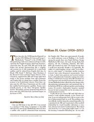
Over time, the trade-off in requirements has divided<br />
electronic packaging into three levels (Fig. 1): device<br />
packaging, board packaging, and system packaging.<br />
Although separation into these levels is not absolute,<br />
they reflect a common method used to organize the<br />
22 JOHNS HOPKINS <strong>APL</strong> TECHNICAL DIGEST, VOLUME 20, NUMBER 1 (1999)
Single-chip<br />
package<br />
Subsystem<br />
chassis<br />
electronic circuitry and categorize electronic packaging<br />
requirements. Each level of packaging provides similar<br />
functions but has a distinct purpose and design.<br />
Device packaging protects the integrated circuit<br />
from corrosion and dissipates heat, creating a component<br />
with an electrical interface and mechanical support<br />
for installation and testing. The printed wiring<br />
board or substrate provides support and interconnection<br />
of the device packages to create electronic subfunctions<br />
suitable for higher-level testing. Box-level<br />
packaging allows for electronic interconnection between<br />
the circuit substrates, and performs housing and<br />
interfacing (such as connectors or keyboards) to the<br />
outside world. Partitioning of the electronic system is<br />
a process that breaks down the complete electronic<br />
circuit into these different levels. The breakdown considers<br />
many factors. This process requires an understanding<br />
of the circuit and its subfunctions, component<br />
and assembly availability, application requirements, as<br />
well as development and testing needs.<br />
Meeting performance requirements is foremost in<br />
electronic packaging. Factors such as signal speed, noise<br />
sensitivity, and electromagnetic interference often dictate<br />
the approach to packaging. Signal speed may require<br />
substrates with a low dielectric constant or impedance<br />
matching. Noisy circuits and circuits that<br />
generate electromagnetic interference may hamper the<br />
proper functioning of adjacent circuits and may need<br />
to be separated from other sensitive circuits by shielding<br />
the device or filtering the power and signal lines. 1<br />
These design considerations often dictate component<br />
Die<br />
MCM<br />
MODERN ELECTRONIC PACKAGING TECHNOLOGY<br />
placement, material choices, and<br />
space allocation.<br />
Incorporation of off-the-shelf<br />
assemblies into the product drives<br />
many packaging decisions. Such<br />
assemblies perform crucial functions<br />
and have their own electrical<br />
and mechanical interfaces. There<br />
may be many electronic, optical,<br />
and mechanical subassemblies to be<br />
incorporated into an assembly, for<br />
example, power supplies, chargecoupled<br />
device cameras, disk<br />
drives, card guides, card cages, and<br />
connectors. For optimum performance,<br />
these subassemblies usually<br />
require exacting design considerations<br />
such as special mounting<br />
brackets and connectors, heat sinking,<br />
and environmental protection.<br />
Although these design factors<br />
are critical in the prototype and<br />
one-of-a-kind hardware that <strong>APL</strong><br />
designs and builds, commercial and<br />
military electronics may have addi-<br />
tional life cycle and consumer appeal issues. Life cycle<br />
issues such as maintainability and testability must be<br />
accommodated. Ergonomics and visual appeal are high<br />
priorities in many consumer electronic products. Finally,<br />
and usually most importantly, the packaging design<br />
must fall within the cost and schedule constraints of the<br />
product.<br />
<strong>Packaging</strong> Reliability<br />
Reliable packaging begins in the design stage. At<br />
this point, the packaging engineer must consider the<br />
potential for thermal, mechanical, and corrosion problems<br />
and determine the best method to minimize their<br />
effects.<br />
Heat is a by-product of the circuit’s function that<br />
raises component temperature and can reduce its reliability.<br />
This temperature increase is an internally generated<br />
stress that must be accounted for in the package<br />
design. Below some threshold, elevated junction temperature<br />
has little effect on the life of a part, but above<br />
that threshold, component life shortens exponentially<br />
with increasing temperature. Thresholds range from<br />
100 to 150°C, 2 depending on the expected product<br />
lifetime, circuit design, and materials. Hence, the package’s<br />
ability to dissipate the device’s heat closely correlates<br />
to its reliability. Proper thermal package design<br />
ensures that the heat dissipation path maintains the<br />
junction temperature below the threshold value. Highpower<br />
devices may require special packaging design and<br />
materials to minimize the junction temperature.<br />
JOHNS HOPKINS <strong>APL</strong> TECHNICAL DIGEST, VOLUME 20, NUMBER 1 (1999) 23<br />
COB<br />
Figure 1. Three levels of packaging: the device is packaged into a component, the<br />
component is mounted on the board, and the board is installed into the subsystem chassis<br />
(MCM = multichip module, COB = chip-on-board).
M. G. BEVAN AND B. M. ROMENESKO<br />
Although most circuit boards have sufficient free air<br />
convection to safely dissipate heat from the device<br />
package, some do not because of high component<br />
densities or high heat generation from power transistors,<br />
or because they operate in the vacuum of space.<br />
In these situations, special features must be incorporated<br />
to increase heat removal from the component. 3 As<br />
with personal computers, fans work well in many terrestrial<br />
environments, increasing heat transfer approximately<br />
an order of magnitude over free convection. 4<br />
In a vacuum, however, it may be necessary to improve<br />
the thermal path between the device package and substrate.<br />
This may be accomplished by filling the gaps<br />
between them with a thermally conductive material.<br />
Thermal resistance may be lowered across the substrate<br />
by bonding a metal heat spreader to it to improve heat<br />
flow to the surrounding box.<br />
In addition to component temperature, the mechanical<br />
environment may reduce the reliability of the electronic<br />
circuit. Specifically, factors such as vibration and<br />
shock, along with temperature changes of the system,<br />
induce forces that can break components and cause<br />
fatigue failure of leads or solder joints. By modeling, the<br />
packaging engineer can identify these potential problems<br />
early in the design stage and implement design<br />
modifications to mitigate these forces.<br />
Over the circuit’s lifetime, the thermal stresses on<br />
the assembly are frequently more destructive than those<br />
created by shock and vibration. In the assembly of<br />
electronic packages and circuit substrates, a variety of<br />
materials are bonded together with adhesives or solders.<br />
Because of the dissimilar thermal expansion of these<br />
materials, temperature changes generate forces at bond<br />
interfaces. For stiff materials, these forces may be sufficiently<br />
large to cause fracture or fatigue failure. Given<br />
the prevalence of problems caused by temperature<br />
cycling in the aerospace industry, spacecraft environmental<br />
stress screening performed by <strong>APL</strong> includes<br />
both temperature cycling and thermal shock tests to<br />
screen for potential problems.<br />
Prevention of temperature cycling damage usually<br />
requires attention to design or material selection. One<br />
common solution is to place an intermediate soft or<br />
spring-like material between the two high-modulus<br />
materials. The intermediate material absorbs the strain<br />
differences between the adjacent materials, reducing<br />
the overall stress. An example of this is the Tessera<br />
chip-scale package (CSP), 5 where silicone rubber is<br />
used between the low-expansion silicon device and the<br />
higher-expansion flex circuit. Alternative solutions<br />
include replacing high-modulus materials with lowmodulus<br />
materials or improving the match in the coefficients<br />
of thermal expansion.<br />
Temperature-induced damage may be particularly<br />
severe when using polymers near their glass transition<br />
temperature, T g. Cooling a polymer below this level<br />
increases the elastic modulus of the polymeric material<br />
by several orders of magnitude, making the polymer<br />
much more stiff and brittle. Although going below the<br />
T g does not damage the material, the change in modulus,<br />
coupled with its dimensional change, can cause<br />
unexpected fracture and fatigue. Concern for this failure<br />
mode has driven the <strong>APL</strong> Space Department<br />
to switch conformal coatings used on printed circuit<br />
boards from Solithane 113/300 (T g = –10°C) to Uralane<br />
5750 (T g = –65°C) (G. Arakaki, personal communication,<br />
Mar 1990; also see Ref. 6).<br />
In oceanic environments, exposure to corrosion can<br />
severely affect the performance and reliability of a<br />
circuit. Moisture, in the form of saltwater or condensing<br />
humidity, promotes corrosion of electronic circuits.<br />
Corrosion products may form between adjacent electrical<br />
conductors, creating an electrical short between<br />
them and interfering with overall circuit performance.<br />
In addition, corrosion may dissolve conductors, thereby<br />
severing the electrical path. The design engineer may<br />
incorporate design features to slow or prevent corrosion,<br />
such as conformal coating and encapsulation of<br />
the circuit boards.<br />
System Partitioning and Modeling<br />
After defining the top-level circuit, its environmental<br />
requirements, and its physical constraints, the system<br />
is partitioned into subsystems and components.<br />
Then, packaging engineers develop detailed designs<br />
that satisfy the requirements of the subsystems. At this<br />
point modeling is often used to predict the thermal and<br />
mechanical behavior of the system so that shortcomings<br />
in the packaging designs can be identified before<br />
fabrication begins.<br />
Partitioning breaks down a system into logical elements,<br />
usually organized by function, testing needs, and<br />
physical size. Additional design considerations that<br />
affect partitioning may include standard circuit board<br />
sizes, thermal management, and available space. Partitioning<br />
is frequently organized by electrical function to<br />
aid in testability, such as having one circuit card dedicated<br />
to power supply or to data communications.<br />
Careful partitioning of the electronic circuit simplifies<br />
testing significantly.<br />
In early Terrier missiles, the electronic components<br />
were hand wired, part by part, to the airframe. 7,8 As a<br />
result, the assembled missiles frequently failed acceptance<br />
tests because of a multitude of problems. The lack<br />
of functional subdivision made testing, troubleshooting,<br />
and repair difficult and time-consuming. Improved<br />
missile designs partitioned the circuits into subsystems<br />
(e.g., attitude control, telemetry, fusing), making the<br />
missile easier to assemble, test, and repair. This same<br />
functional division concept applies to the different<br />
levels of packaging.<br />
24 JOHNS HOPKINS <strong>APL</strong> TECHNICAL DIGEST, VOLUME 20, NUMBER 1 (1999)
Other issues besides testing drive<br />
the partitioning decisions. Partitioning<br />
usually accommodates the<br />
normal manufacturing sequence to<br />
minimize handling and cross-contamination.<br />
Systems may require<br />
additional volume and features to<br />
allow for repair, or they may be<br />
partitioned to minimize the amount<br />
of circuitry in an adverse environment.<br />
For example, on spacecraft,<br />
even though the sensors are exposed<br />
to the space environment,<br />
the boxes containing most of the<br />
support electronics are placed under<br />
thermal blankets to protect<br />
them from the temperature extremes<br />
and temperature cycling encountered<br />
in space.<br />
Analytical modeling is an essential<br />
tool in the partitioning and development<br />
of reliable electronic<br />
packaging designs. Modeling offers<br />
significant cost and schedule savings<br />
for complex systems, particularly<br />
those incorporating expensive<br />
and long lead-time subassemblies.<br />
Using specialized software, electrical<br />
modeling can be performed to<br />
simulate circuit performance. The<br />
mechanical and thermal behavior<br />
of the system can be modeled using<br />
finite element methods 9 during<br />
power cycling, temperature cycling,<br />
and shock and vibration testing.<br />
By doing so, problems can be<br />
identified and fixed, with minimal<br />
impact on cost and schedule, before<br />
any hardware is fabricated.<br />
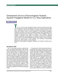
Figure 2 shows how modeling<br />
can predict problems before assembly.<br />
Figure 2a is a schematic illustration<br />
of the full signal translator<br />
circuit board. Figures 2b and c illustrate<br />
the results of thermal and mechanical<br />
modeling. Thermal modeling<br />
predicts the temperature<br />
distribution across the board. Figure<br />
2b shows that the ambient temperature<br />
must be kept at least 38°C<br />
below the critical junction temperature<br />
of the upconverter. The mechanical<br />
analysis in Fig. 2c shows<br />
the deflection of the assembled<br />
printed wiring board under a sinusoidal<br />
vibration. The software not<br />
(a)<br />
(b)<br />
(c)<br />
Primary side<br />
Maximum deflection<br />
MODERN ELECTRONIC PACKAGING TECHNOLOGY<br />
Downconverter<br />
(400 mW)<br />
250-mW T08<br />
can component<br />
Secondary side<br />
Upconverter<br />
(800 mW)<br />
75-mW T08<br />
can components<br />
Temperature<br />
rise (°C)<br />
37<br />
34<br />
32<br />
29<br />
26<br />
24<br />
21<br />
18<br />
16<br />
13<br />
10<br />
8<br />
5<br />
2<br />
Figure 2. Modeling is used to predict problems before assembly. (a) Part locations on the<br />
front and back of a full signal translator (FST) circuit. (b) Thermal model of the FST showing<br />
predicted component and substrate temperature (and its distribution over ambient conditions).<br />
(c) Mechanical modeling showing first-mode deflection of the FST board in vibration;<br />
the mass of the upconverter causes most of the deflection.<br />
JOHNS HOPKINS <strong>APL</strong> TECHNICAL DIGEST, VOLUME 20, NUMBER 1 (1999) 25
M. G. BEVAN AND B. M. ROMENESKO<br />
only predicts the maximum deflection, it also predicts<br />
the distribution of the deflection across the board, accounting<br />
for variations in mass and specific locations<br />
of mounting points. By knowing the deflection locations<br />
and magnitudes at the design stage, additional<br />
stiffeners and mounting points may be incorporated in<br />
the design before the hardware is built.<br />
Once the hardware is built, the thermal model is<br />
verified by measuring the temperature at critical locations.<br />
Since measuring deflection during vibration is<br />
somewhat difficult, strain or acceleration measurements<br />
obtained via gauges and accelerometers, respectively,<br />
may be used to validate the mechanical behavior<br />
of a model.<br />
DEVICE PACKAGING<br />
The first or lowest level of packaging is semiconductor<br />
device packaging. Not long ago, the selection of<br />
package styles was limited. The dual-inline package<br />
(DIP) dominated the semiconductor market and represented<br />
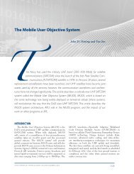
the majority of electronic packages sold. Today,<br />
with the drive toward miniaturization, combined<br />
with the lack of a clearly superior miniature package,<br />
many distinct package styles are available (Fig. 3),<br />
ranging from traditional DIP to chip-on-board (COB).<br />
They also range in price and area of substrate required<br />
for installation, each reflecting a different testing, assembly,<br />
and performance optimum.<br />
The primary motives for packaging the device before<br />
assembly onto a circuit board are to allow for complete<br />
testing and to protect the device from contamination.<br />
Without packaging, testing of bare devices is expensive<br />
and difficult because of the tiny dimensions involved.<br />
When packaged, a device has far less stringent handling<br />
requirements than a bare device. Bare silicon devices<br />
must be handled cautiously in a clean-room environment.<br />
Soldering and normal handling during assembly<br />
leave contamination that often causes corrosive failure<br />
of unprotected devices. Improper handling easily<br />
damages the tiny wire interconnections on devices. For<br />
0<br />
1 2 3 4 5<br />
Centimeters<br />
these reasons devices are usually packaged before testing<br />
and further assembly.<br />
The design of the device packages is driven by many<br />
factors, including the number of leads and their routing<br />
on the substrate as well as the ability to dissipate the<br />
heat generated by the device. The external lead geometry<br />
must meet the customer’s circuit board design constraints,<br />
assembly needs, and cost requirements. To conserve<br />
the space on a circuit board, customers frequently<br />
want the device in the smallest package possible.<br />
Smaller packages permit significant system miniaturization.<br />
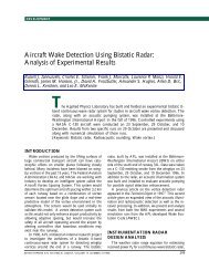
Figure 4 shows how smaller packages may have the<br />
same number of leads as larger packages but cover a<br />
considerably smaller substrate area. However, miniaturization<br />
of packages frequently results in increased costs<br />
of assembly.<br />
The redesign of the Glacier spaceborne imager built<br />
by the <strong>APL</strong> Space Department exemplifies how changing<br />
component packaging can reduce overall system<br />
size. The imager was an existing circuit design that was<br />
repackaged using several new packaging technologies<br />
(see the article by Le et al., this issue). By stacking<br />
dynamic random-access memory vertically, about a 5:1<br />
reduction was realized in the number of packages, with<br />
a corresponding reduction in substrate area. Attaching<br />
bare, unpackaged devices directly to the substrate instead<br />
of packaged devices contributed to further miniaturization.<br />
However, these savings came at a price.<br />
Stacked memory chips are more expensive than separately<br />
packaged devices. Also, attaching unpackaged<br />
devices introduces a host of potential problems: unpackaged<br />
and incompletely tested parts create an increased<br />
amount of rework, increased rework difficulty,<br />
additional costs associated with encapsulating the device<br />
after attachment, and reliability unknowns found<br />
with any new assembly method. 10<br />
Device <strong>Packaging</strong> Processes<br />
Figure 3. Some components available today are (clockwise from lower left) a 44-pin Jleaded<br />
plastic quad flatpack (PQFP), 20-pin thin small-outline package, 84-pin J-leaded<br />
PQFP, 208-pin QFP, 100-pin QFP, and 40-pin dual-inline package.<br />
A variety of processes are used in device packaging.<br />
These processes create a package that shields the die<br />
from contamination and damage<br />
while electrically connecting it<br />
to the exterior. One of the most<br />
critical processes is the electrical<br />
interconnection of the device to<br />
the leads. This can be achieved<br />
through, for example, wire bonding,<br />
tape-automated bonding<br />
(TAB), and flip-chip soldering. 11<br />
Historically, wire bonding has been<br />
the dominant method of interconnection.<br />
When a wire bond is<br />
made, the wire bonding machine<br />
welds one end of the wire to the<br />
device and the other end to the<br />
substrate or lead frame. Wire bonds<br />
26 JOHNS HOPKINS <strong>APL</strong> TECHNICAL DIGEST, VOLUME 20, NUMBER 1 (1999)
Figure 4. Plot showing the amount of substrate area required per lead and how this ratio<br />
varies with package style and total number of leads on the package. (DIP = dual-inline<br />
package, PLCC = plastic-leaded chip carrier, TSOP = thin small-outline package, QFP =<br />
quad flatpack, BGA = gall-grid array, PBGA = plastic BGA.)<br />
are made using thin gold or aluminum-alloy wire, typically<br />
with a diameter of 25 m (0.001 in.). Wire bonds<br />
are short, in the range of 1 to 3 mm (0.05–0.15 in.).<br />
Because they are so short and fragile, they impose additional<br />
packaging requirements. The frail wire bonds<br />
must be protected from damage and contamination,<br />
either by encasement in a rigid package or by molding<br />
in plastic.<br />
In the 1960s, IBM developed an alternative to wire<br />
bonding, now called flip-chip technology, which uses<br />
a solder joint to form an electrical, thermal, and<br />
mechanical connection to the substrate. The flip<br />
chip process produces higher yields and more rapid<br />
throughput than wire bonding. Additionally, it requires<br />
less space on a substrate than wire bonding and<br />
permits rework. As expected, these advantages also<br />
have their cost. Flip-chip technology is more challenging<br />
to implement for much of the electronics fabrication<br />
industry. The process requires special metallization<br />
during wafer fabrication. A barrier layer and a<br />
solderable top-layer metallization must be applied over<br />
the aluminum bond pads to provide a solderable surface<br />
and prevent aluminum dissolution in the solder.<br />
The barrier layer must be compatible with a solderable<br />
top layer, protect the surface of the semiconductor<br />
device from contamination, and prevent undesirable<br />
metallurgical reactions between the solderable layer<br />
and the device metallization. Flip-chip technology<br />
also requires a nonstandard substrate and processing<br />
of the substrate to reduce the size of the pads, vias,<br />
and traces. For these reasons, the cost of a flip chip<br />
is about $0.05 per connection versus less than<br />
MODERN ELECTRONIC PACKAGING TECHNOLOGY<br />
$0.001 per connection for wire<br />
bonding. 12<br />
The TAB method is an alternative<br />
to wire bonding and flip-chip<br />
bonding. It incorporates the bonding<br />
region with the lead frame fanout.<br />
A TAB structure typically begins<br />
as a thin laminate of copper on<br />
a polyimide film carrier. The conductors<br />
are etched out of the copper<br />
to form the electrical interconnection<br />
between the chip and the outside.<br />
The polyimide holds the copper<br />
conductors in place to facilitate<br />
rapid assembly. TAB technology<br />
uses several metallurgical coatings<br />
for conductors and bonding areas.<br />
Methods of connecting the TAB to<br />
the chip include thermocompression,<br />
thermosonic and ultrasonic<br />
bonding, and soldering. Joints may<br />
be bonded one at a time or simultaneously.<br />
The process is rapid<br />
and has found niches in certain<br />
markets. In low-volume markets (e.g., high-performance<br />
military electronics), TAB offers a highly reliable, highperformance<br />
interconnect method with a minimum of<br />
inductance and impedance. In high-volume markets,<br />
TAB offers a low-profile way to assemble circuits for<br />
applications such as digital watches and cameras.<br />
Wire bonding, flip-chip soldering, and TAB may<br />
require additional features for mechanical and thermal<br />
interconnection. In wire bonding, the back of the<br />
device must be attached to a substrate using an adhesive,<br />
gold-silicon eutectic solder or a glass compound.<br />
The adhesive is often filled with silver or gold powder,<br />
making it electrically conductive and enhancing thermal<br />
conductivity. Because of the large surface area involved,<br />
device attachment provides a good thermal<br />
connection and high mechanical strength.<br />
Flip-chip technology does not require additional mechanical<br />
attachment because the solder joints provide<br />
sufficient support to withstand shock and vibration<br />
forces. The flip-chip solder joints, by themselves, can<br />
dissipate considerable device heat. If further measures<br />
are needed to remove heat, two options are available.<br />
In the most demanding applications, heat may be removed<br />
from the back side of the flip chip through<br />
conduction by using a small block of water-cooled copper<br />
such as that used in the IBM thermal control<br />
module. 13 The second option is to fill the gap between<br />
the flip chip and the substrate with an encapsulant,<br />
called “underfill,” to increase thermal conductivity.<br />
This underfill also provides environmental protection<br />
to the device circuitry and improves the thermal fatigue<br />
resistance of the solder joints.<br />
JOHNS HOPKINS <strong>APL</strong> TECHNICAL DIGEST, VOLUME 20, NUMBER 1 (1999) 27
M. G. BEVAN AND B. M. ROMENESKO<br />
Wire bonded, soldered, and TAB-mounted devices<br />
all require environmental protection from handling,<br />
contamination, and corrosion. This protection takes<br />
one of several forms. Devices may be sealed in the<br />
cavity of a ceramic or metal hermetic package whose<br />
walls are impervious to humidity and contamination,<br />
encapsulated in epoxy or silicone, or coated with inorganic<br />
materials such as silicon nitride. A common encapsulant<br />
is a filled epoxy that has been injection<br />
molded around the device and its lead frame. This<br />
material is used extensively for commercial components.<br />
As an alternative to injection-molded materials,<br />
a castable encapsulant may be applied, either as an<br />
underfill for flip-chip assembly or mounded as a “globtop”<br />
over a wire bonded device to protect the wires.<br />
Component Package Styles<br />
One of the oldest and most common component<br />
packages is the DIP noted previously, which is fabricated<br />
in three basic configurations: molded plastic, ceramic,<br />
and side-brazed. The plastic injection-molded<br />
DIP dominates cost-sensitive and noncritical applications,<br />
whereas the ceramic and side-brazed packages,<br />
with their hermetic seals, are used in high-cost, highreliability<br />
applications found in military, space, and<br />
demanding commercial electronic systems. The DIP<br />
has two rows of leads separated by 0.3, 0.4, or 0.5 in.,<br />
with the individual leads spaced 0.1 in. apart. The size<br />
of the DIP is based not so much on the device size but<br />
rather on the area required by the spacing of the leads.<br />
The lead layout of the DIP consumes the greatest area<br />
per lead of any device packaging method.<br />
The DIP package is being replaced with surfacemounted<br />
packages for a number of reasons. With devices<br />
becoming faster and more complex, the length of<br />
the component leads and substrate traces must be reduced<br />
as the number of leads is increased. The increased<br />
number of components parallels the need to<br />
reduce the overall size of the system. Surface-mounted<br />
packages satisfy these requirements in a variety of<br />
shapes and sizes (Fig. 3). These packages can be grouped<br />
into two general styles, leaded and area array. Figure 4<br />
shows how surface-mounted packages, particularly area<br />
arrays, offer significant area savings when they replace<br />
DIPs. Area arrays are a class of packages that distribute<br />
leads on a grid pattern over the package bottom rather<br />
than only around its periphery; this method makes high<br />
lead count devices much more practical.<br />
The area savings of surface-mounted components<br />
are often so great that substrate routing difficulties<br />
place more constraints on component density than the<br />
component size. A substrate designed to fully exploit<br />
the potential component density may have many layers<br />
and may be costly. By limiting the board thickness<br />
to four layers of metallization, the board cost can be<br />
reduced significantly with only a slight compromise of<br />
component density.<br />
The number of leaded surface-mount package styles<br />
has proliferated without a single unifying standard.<br />
Several package design standards have been developed,<br />
each defining different package geometries and different<br />
lead layouts. Each package style has unique benefits<br />
and constraints. As the lead size becomes smaller and<br />
the number of leads increases, the difficulty of handling<br />
and installation increases. Some package styles are<br />
better suited for heat dissipation than others, a factor<br />
vital in space and temperature-critical applications.<br />
The development of area array surface-mounted<br />
packages (Fig. 5) offers both the benefit of increased<br />
lead densities and a more forgiving manufacturing process.<br />
These packages distribute the solder joints, which<br />
number from 48 to over 1000, 14 across the bottom<br />
surface of the package instead of along the edges. This<br />
distribution allows for larger solder joints and an increased<br />
distance between them, thereby improving<br />
solder joint manufacturing yields and reliability. These<br />
solder joints provide both electrical connection and<br />
mechanical support for the component.<br />
An early implementation of area array interconnects<br />
was the pin-grid arrays found on microprocessors in the<br />
early 1990s. Today, two leadless types of area array<br />
packages are being implemented, the ball-grid array<br />
(BGA) and the chip-scale package (CSP). The distinction<br />
between these packages is more an issue of scale<br />
than design. The BGA is larger and is built on a printed<br />
circuit board–like substrate. It has solder balls on the<br />
bottom in a grid with nominally 1- to 1.5-mm (0.04to<br />
0.12-in.) spacings. The CSPs are approximately 20%<br />
larger than the semiconductor devices they contain,<br />
having correspondingly smaller solder balls and grid<br />
spacings ranging from 0.5 mm (0.020 in.) to less than<br />
0.1 mm (0.004 in.). To enhance solder joint fatigue life,<br />
the solder joints on CSPs are typically encapsulated<br />
with limited-expansion epoxy.<br />
These package styles are so efficient in their use<br />
of substrate space that, to ease routing and reduce<br />
substrate costs, only the outer two or three rings of<br />
solder joints are often present or electrically active.<br />
Among the most significant factors that limit area array<br />
packages are their sparse commercial availability and<br />
the inability to visually examine the finished solder<br />
joints. This inability is a process quality issue that gives<br />
many companies problems. Nondestructive examination<br />
of the solder joints requires an X-ray machine<br />
capability that few electronic assembly companies possess.<br />
Transmission X-ray analysis detects many types of<br />
solder joint defects. A detailed, nondestructive analysis<br />
of solder joint shape requires X-ray laminography, but<br />
most companies are satisfied with nondestructive<br />
transmission X-ray analysis combined with sampling<br />
methods using destructive analysis techniques. With<br />
28 JOHNS HOPKINS <strong>APL</strong> TECHNICAL DIGEST, VOLUME 20, NUMBER 1 (1999)
(a)<br />
(b)<br />
0<br />
(c)<br />
Gold-plated<br />
bond ribbon<br />
0<br />
Solder balls,<br />
eutectic or solid core<br />
(solid core shown)<br />
1 2 3 4 5<br />
Centimeters<br />
1 2<br />
Centimeters<br />
Flexible circuit tape<br />
with or without adhesive<br />
(shown with adhesive)<br />
Elastomer pad<br />
Silicon die<br />
the high yields possible with BGAs and CSPs,<br />
many companies choose to forgo the X-ray inspection<br />
of solder joints and, instead, monitor the assembly process<br />
closely.<br />
Heat dissipation is usually not a problem for BGAs.<br />
For example, Olin has developed a high-performance<br />
256-ball BGA (27 27 mm) package that, when dissipating<br />
1 W, can be as little as 12.5°C over ambient<br />
temperatures with natural convection. 15<br />
The reliability of these new surface-mounted area<br />
arrays has been tested and found to be satisfactory for<br />
commercial applications; however, their history of use<br />
is short—too short to build confidence for space and<br />
military applications. Efforts are now under way to<br />
Soldermask or<br />
coverlayer<br />
Low-modulus<br />
encapsulant<br />
Figure 5. Several views and implementations of array packages. (a) Top and bottom views<br />
of a ball-grid array. (b) Bottom view of chip-scale packages (CSPs). (c) Cross-sectional<br />
view of a CSP. (Photograph courtesy of Tessera, Inc.)<br />
MODERN ELECTRONIC PACKAGING TECHNOLOGY<br />
establish reliability limits for highreliability<br />
applications. 16 Today, the<br />
use of BGA and CSP packages in<br />
these applications is limited to situations<br />
where no other traditional<br />
package can meet the requirements.<br />
MULTICHIP MODULE<br />
PACKAGING<br />
Sometimes it is advantageous to<br />
package several devices in one<br />
package, forming a multichip module<br />
(MCM). By combining individual<br />
devices and components into a<br />
single package, significant miniaturization<br />
is achieved over individually<br />
packaged devices mounted on<br />
a substrate. In doing so, multichip<br />
packaging muddles the distinction<br />
between device packaging and circuit<br />
boards.<br />
The combination of Level 1 and<br />
2 packaging into an MCM offers a<br />
significant advantage of low-volume,<br />
high-density packaging commonly<br />
found in the aerospace and<br />
military markets. In low volume, an<br />
MCM is an economical alternative<br />
to a custom-designed integrated circuit,<br />
since much of the miniaturization<br />
is achieved without the high<br />
initial cost of integrated circuit design.<br />
Many highly integrated devices<br />
began as an MCM before subsequent<br />
production volume justified a<br />
commitment to redesign as a single<br />
silicon circuit. The disadvantages to<br />
MCM technology over individually<br />
packaged devices are significantly<br />
higher costs of the assembly and<br />
decreased yield caused by using in-<br />
completely tested silicon die. Verification of device<br />
performance without packaging (i.e., the “knowngood-die”<br />
problem) has received considerable attention<br />
in the electronics industry, but little progress has been<br />
made in the ability to do so. The critical issues are cost<br />
and system yield, for without the high probability of a<br />
working device, assembly yields are low (Fig. 6), and<br />
the test and rework costs increase exponentially.<br />
Multichip packaging substrates range widely in<br />
cost and interconnect density. Those MCMs with<br />
printed circuit board substrates have the lowest cost<br />
and lowest interconnect density; those with singlecrystal<br />
silicon substrates have the highest cost and<br />
highest interconnect density. Alumina and other<br />
JOHNS HOPKINS <strong>APL</strong> TECHNICAL DIGEST, VOLUME 20, NUMBER 1 (1999) 29<br />
3
M. G. BEVAN AND B. M. ROMENESKO<br />
Probability of<br />
system functioning (%)<br />
100<br />
90<br />
80<br />
70<br />
60<br />
50<br />
40<br />
30<br />
20<br />
10<br />
0<br />
1 20 40<br />
60<br />
Number of parts in system<br />
ceramic substrate technologies represent cost/density/<br />
performance trade-offs between these two extremes.<br />
Traditionally, suppliers of MCMs for military and<br />
aerospace applications place them in hermetic packages<br />
constructed of ceramic, glass, and metal. Hermetic<br />
packages provide a barrier to moisture and relatively<br />
constant mechanical and electrical properties over a<br />
wide temperature range. A less expensive alternative is<br />
encapsulation of MCM circuits in an epoxy or silicone<br />
polymer. These encapsulants slow moisture ingress<br />
and mitigate corrosion, meeting the reliability requirements<br />
of many applications. Although their protection<br />
is not as assured, encapsulation is sufficient for many<br />
environments.<br />
Multichip packaging has a long history of use at <strong>APL</strong><br />
in satellites and special-purpose circuits (Fig. 7). 17 The<br />
Laboratory has fabricated MCMs on several types of<br />
substrates including silicon wafer, low-temperature cofired<br />
ceramic, and thick film ceramic. These MCMs are<br />
typically mounted in hermetic packages that are sealed<br />
by soldering or welding. (See the article by Blum et al.,<br />
this issue, for further details on MCM development at<br />
<strong>APL</strong>.)<br />
THE CIRCUIT SUBSTRATE<br />
The purpose of the circuit substrate is to provide<br />
a mounting surface and electrical interconnection<br />
for the components. For most electronics, the circuit<br />
substrate turns off-the-shelf components into a custom,<br />
application-specific circuit. Considerations in the<br />
choice of a substrate and its design include such assembly<br />
processes and performance issues as signal delay and<br />
capacitance. The circuit substrate should allow for<br />
testing and repair before integration into the next level.<br />
80<br />
2.0<br />
100<br />
1.6<br />
1.2<br />
Percent<br />
90–100<br />
80–90<br />
70–80<br />
60–70<br />
50–60<br />
40–50<br />
30–40<br />
20–30<br />
0 10–20<br />
0.4<br />
0–10<br />
0.8<br />
Defect rate<br />
of parts (%)<br />
Figure 6. Plot of system yields (probability of functioning) with the reliability of the<br />
component and the number of parts in the system.<br />
In designing a circuit substrate,<br />
the shock and vibration environment<br />
of the application must be<br />
accommodated. Because components<br />
are small, damage from shock<br />
and vibration forces usually is not<br />
an issue in device packaging. With<br />
larger substrates like circuit boards,<br />
however, both mass and moment<br />
increase, thereby increasing the potential<br />
for damage. As noted earlier,<br />
typical methods to reduce shock<br />
and vibration damage include the<br />
addition of stiffeners and extra<br />
mounting points. Reducing the distance<br />
between mounting points<br />
mitigates the deflection from the<br />
shock and vibration and changes<br />
the fundamental resonant frequency.<br />
Adding stiffeners to the substrate<br />
may also reduce the deflec-<br />
tion and stresses on the components.<br />
Conformal coatings are applied to assembled circuit<br />
substrates for many purposes. If the circuit substrate is<br />
exposed to moisture and ionic contamination, it may<br />
require conformal coating to insulate the surface. Some<br />
circuits on the Tomahawk cruise missile are immersed<br />
in fuel, requiring conformal coatings that not only protect<br />
the circuit from corrosion but are also stable in fuel.<br />
The Space Department uses conformal coatings not so<br />
much to prevent corrosion but to dampen shock and<br />
vibration as well as to prevent stray metal contamination<br />
from shorting the circuit. Conformal coatings may<br />
have one of several polymer chemistries. 11 Polyurethane,<br />
silicone, and Parylene conformal coatings are<br />
commonly applied to circuit boards assembled at <strong>APL</strong>.<br />
Figure 7. An <strong>APL</strong>-designed and -fabricated static random-access<br />
memory module using MCM technology. Module area is 3.5 <br />
4.1 cm.<br />
30 JOHNS HOPKINS <strong>APL</strong> TECHNICAL DIGEST, VOLUME 20, NUMBER 1 (1999)
A printed circuit board is normally fabricated as an<br />
epoxy or polyimide fiberglass composite structure. It<br />
contains layers of copper traces on the surface and<br />
within the structure that are connected by metallized<br />
vias. Components are soldered to the surface and in<br />
through-holes. The materials and processes used at<br />
<strong>APL</strong> to fabricate substrates were developed to maximize<br />
electrical performance within cost and durability<br />
constraints. For example, the coefficients of in-plane<br />
thermal expansion of the composite and the copper<br />
traces are similar, minimizing substrate warpage during<br />
soldering and temperature cycling.<br />
Most vias extend through the entire thickness of the<br />
board, connecting any of the inner layers of the board<br />
to the surface. This configuration limits the routing of<br />
traces to the space between the vias. Blind and buried<br />
vias (i.e., vias that do not extend through the board)<br />
avoid this constraint but significantly increase the price<br />
of the board. A blind via extends from the surface of<br />
the substrate to a dead end at an inner layer; a buried<br />
via begins and ends on inner layers of the substrate.<br />
These special types of vias ease routing by limiting via<br />
length, allowing a trace to be routed above or below<br />
the area that would otherwise be occupied by the via.<br />
Although boards with these special types of vias are<br />
costly, they may still be more economical than the use<br />
of silicon or ceramic alternatives.<br />
Several variations to the traditional board offer alternative<br />
packaging options. New advances in ceramic<br />
substrates and boards allow passive resistors and capacitors<br />
to be buried in the substrate, which frees up additional<br />
space on the surface of the substrate. However,<br />
these built-in components do not have the range of<br />
values, tolerances, or performance available from discrete<br />
components.<br />
For high-frequency circuits that are particularly sensitive<br />
to capacitive coupling, the circuit substrate must<br />
often be constructed with a special, uniform dielectric<br />
material such as Duroid. The Duroid dielectric is a<br />
mixture of alumina powder and polytetrafluoroethylene<br />
that has a controlled, dielectric constant which<br />
varies little across the substrate. The copper traces on<br />
these boards are laid out using special rules to optimize<br />
circuit performance and minimize reflections. These<br />
rules include careful grounding, rounding the corners<br />
of traces, and choosing trace layouts with matched<br />
impedance to tune the circuit.<br />
Circuit substrate technology has moved from the<br />
traditional flat, rigid boards to flexible substrates and<br />
rigid-flex boards, a hybrid of the rigid and flexible technologies.<br />
Flexible substrates are made from sheets of<br />
polyimide (e.g., Kapton), laminated with copper foil to<br />
form traces. These may have several layers like rigid<br />
substrates. Flexible substrates permit rolling and folding<br />
to fit the space available, which has many advantages<br />
in the packaging of electronics in constrained areas<br />
MODERN ELECTRONIC PACKAGING TECHNOLOGY<br />
or in areas with odd shapes. It also permits the circuit<br />
to be assembled and tested flat, then folded into the<br />
available space. Many consumer electronic products<br />
such as cameras and watches contain such flexible substrates.<br />
Rigid-flex boards combine the advantages of both<br />
flexible and rigid substrates. Such composite structures<br />
use flexible segments to connect rigid portions of the<br />
circuit board (Fig. 8). One common application of<br />
rigid-flex boards is for motherboards. Before rigid-flex<br />
technology, the motherboard was connected to the<br />
external connectors using up to hundreds of discrete<br />
wires. This manual wiring process was time-consuming<br />
and error prone. By substituting a segment of flex<br />
substrate for the discrete wires, the wiring process is<br />
reduced to soldering the connector pins onto a board,<br />
thereby eliminating problematic hand wiring.<br />
CHASSIS-LEVEL PACKAGING<br />
Chassis-level packaging connects the circuit boards<br />
and mounts them into a chassis, forming a system or<br />
subsystem. For many systems (e.g., personal computers),<br />
this is the level of packaging seen by the user. In<br />
satellites, this chassis-level package is connected to a<br />
structural frame and electrically connected to other<br />
chassis having different functions. The design phase of<br />
chassis packaging has similar mechanical, thermal, and<br />
materials considerations found in device and circuit<br />
board packaging. For <strong>APL</strong>’s typical spacecraft and for<br />
most avionics applications, card guides hold the circuit<br />
boards by their sides in an aluminum housing, with a<br />
motherboard connecting the different boards (Fig. 9).<br />
This layout usually reflects the system partitioning to<br />
facilitate testing. Card guides ease insertion and removal<br />
of circuit boards while increasing heat dissipation. To<br />
facilitate electrical testing, extender cards can be used<br />
with this layout to probe individual boards while operating<br />
the entire box.<br />
Traditionally, systems engineering allots each subsystem<br />
or major function its own chassis. Each chassis<br />
would be connected to the system through a power line<br />
and data bus and contain its own power supply and data<br />
transfer functions. To conserve space, reduce costs, and<br />
improve reliability, many newer systems are being packaged<br />
into a common chassis. These common chassis<br />
contain circuit boards for several electronic functions,<br />
located in one housing, on a common motherboard.<br />
By combining many cards and functions into one<br />
housing, redundant power supplies, data transfer<br />
circuits, and harnesses are eliminated. This increases<br />
packaging density and potentially improves system reliability.<br />
Although this packaging concept has advantages,<br />
it complicates testing, heat removal, and system<br />
integration. Because of electromagnetic interference, it<br />
JOHNS HOPKINS <strong>APL</strong> TECHNICAL DIGEST, VOLUME 20, NUMBER 1 (1999) 31
M. G. BEVAN AND B. M. ROMENESKO<br />
Figure 8. Four boards and their interconnections are combined into one rigid-flex assembly. The overall assembly size is 13.3 8.3 <br />
6.5 cm.<br />
may not meet the special requirements of radiofrequency<br />
and microwave circuits.<br />
A new development in card cages is the substitution<br />
of graphite-epoxy composite materials for aluminum. 18<br />
With graphite-epoxy’s high modulus-to-density ratio<br />
and high thermal conductivity, this substitution can<br />
reduce the overall weight of card cages. However, it also<br />
requires careful layout and analysis to achieve weight<br />
savings while meeting thermal dissipation requirements.<br />
19 In choosing a composite<br />
card cage, the additional cost of<br />
design, analysis, and fabrication<br />
must be balanced with the potential<br />
weight savings and improvement<br />
in thermal performance.<br />
CONCLUSION<br />
<strong>Electronic</strong> packaging technology<br />
applies a diverse range of engineering<br />
practices to the packaging<br />
of electronic circuits. After the requirements,<br />
constraints, and environment<br />
of the electronic circuit<br />
are considered, the system is partitioned<br />
into component, substrate,<br />
and box levels, each one bringing<br />
unique but similar electrical, mechanical,<br />
and thermal concerns.<br />
Analytical modeling may be performed for each level<br />
of packaging to simulate the electrical, mechanical, and<br />
thermal behavior of the system to identify and correct<br />
problems in the design stage. To simplify testing, each<br />
level of packaging typically isolates a function of the<br />
electronic circuit. Although these levels may not always<br />
be distinct, they form the building blocks of the<br />
total circuit. As circuits become more complex and<br />
miniaturized, electronic packaging needs become more<br />
Figure 9. Exploded view of a box and circuit cards used in the Near Earth Asteroid<br />
Rendezvous command/telemetry processor (24.4 23.9 17.2 cm, 10.9 lb).<br />
32 JOHNS HOPKINS <strong>APL</strong> TECHNICAL DIGEST, VOLUME 20, NUMBER 1 (1999)
challenging, and careful electronic packaging becomes<br />
more crucial to mission success.<br />
SELECTED BIBLIOGRAPHY<br />
Books<br />
<strong>Electronic</strong> <strong>Packaging</strong> and Interconnection Handbook, C. A. Harper (ed.), McGraw-<br />
Hill, New York (1991).<br />
Microelectronics <strong>Packaging</strong> Handbook, 3 vols.: Semiconductor <strong>Packaging</strong>, Subsystem<br />
<strong>Packaging</strong>, and <strong>Technology</strong> Drivers, R. R. Tummula, E. J. Rymaszewski, and<br />
A. G. Klopfenstein, (eds.), Chapman and Hall, New York (1997).<br />
Journals<br />
Components, <strong>Packaging</strong> and Manufacturing <strong>Technology</strong>, published by IEEE.<br />
Microcircuits and <strong>Electronic</strong> <strong>Packaging</strong>, published by The International Microelectronics<br />
and <strong>Packaging</strong> Society.<br />
Proceedings<br />
<strong>Electronic</strong>s Components and <strong>Technology</strong> Conference, sponsored by the CPMT-<br />
IEEE, <strong>Electronic</strong> Industries Association.<br />
International Symposium and Exhibit of Microelectronics, sponsored by The<br />
International Microelectronics and <strong>Packaging</strong> Society.<br />
REFERENCES<br />
1Davidson, E. E., Katopis, G. A., and Sudo, T., “<strong>Packaging</strong> Design,” Chap. 3,<br />
in Subsystem <strong>Packaging</strong>. Microelectronics <strong>Packaging</strong> Handbook, R. R. Tummula,<br />
E. J. Rymaszewski, and A. G. Klopfenstein (eds.), Chapman and Hall, New<br />
York (1997).<br />
2<br />
Altoz, F. E., “Thermal Management,” in <strong>Electronic</strong> <strong>Packaging</strong> and Interconnection<br />
Handbook, C. A. Harper (ed.), McGraw Hill, New York, pp. 2.1–2.99<br />
(1991).<br />
3<br />
Charles, Jr., H. K., and Hoffman, E., “Extreme Environments: Designing<br />
Packages for Space and Avionics,” Advanced <strong>Packaging</strong> Magazine, pp. 10–14<br />
(Fall 1993).<br />
4<br />
Simons, R. E., Antonetti, V. M., Nakayama, W., and Oktay, S., “Heat<br />
Transfer in <strong>Electronic</strong> Packages,” Chap. 4, in Semiconductor <strong>Packaging</strong>.<br />
Microelectronics <strong>Packaging</strong> Handbook, R. R. Tummula, E. J. Rymaszewski, and<br />
A. G. Klopfenstein (eds.), Chapman and Hall, New York (1997).<br />
THE AUTHORS<br />
MODERN ELECTRONIC PACKAGING TECHNOLOGY<br />
5 DiStefano, T., and Fjelstad, J., “Chip-Scale <strong>Packaging</strong> Meets Future Design<br />
Needs,” Solid State Technol., pp. 82–90 (Apr 1996).<br />
6 Lewis, F., and O’Donnell, T., “Qualification of Uralane 5750 A/B (LV) for<br />
Flight Applications,” in Proc. Fifth Int. SAMPE <strong>Electronic</strong>s Conf., pp. 606–614<br />
(18–20 Jun 1991).<br />
7 The First Fifty Years: A Pictorial Account of The <strong>Johns</strong> <strong>Hopkins</strong> University<br />
Applied Physics Laboratory Since Its Founding in 1942, Shneidereith and Sons,<br />
Baltimore, MD (1983).<br />
8 The Terrier 1B Missile, TG 231-1, JHU/<strong>APL</strong>, Laurel, MD (Feb 1954).<br />
9 Clatterbaugh, G. V., and Charles, Jr., H. K., “Thermal and Thermomechnical<br />
Analysis and Testing of <strong>Electronic</strong> <strong>Packaging</strong> Systems,” <strong>Johns</strong> <strong>Hopkins</strong> <strong>APL</strong><br />
Tech. Dig. 7(3), 279–283 (Jul–Sep 1986).<br />
10 Charles, Jr., H. K., and Petek, J. M., “Known Good Die, Die Replacement<br />
(Rework), and Their Influences on Multichip Module Cost,” in Proc. 48th<br />
IEEE <strong>Electronic</strong>s Components and <strong>Technology</strong> Conf., Seattle, WA, pp. 909–915<br />
(May 1998).<br />
11 Charles, Jr., H. K., “Materials in <strong>Electronic</strong> <strong>Packaging</strong> at <strong>APL</strong>,” <strong>Johns</strong> <strong>Hopkins</strong><br />
<strong>APL</strong> Tech. Dig. 14(1), 51–67 (1993).<br />
12 Charles, Jr., H. K., “Cost Versus <strong>Technology</strong> Trade-Offs for Multichip<br />
Modules,” ISHM J. Microelectron. Electron. Packag. 19(3), 295–300 (1996).<br />
13 Simmons, R. E., “The Evolution of IBM High Performance Cooling<br />
<strong>Technology</strong>,” IEEE Trans. Compon. Hybrids Manuf. Technol. Part A 18(4),<br />
805–811 (1995).<br />
14 Costlow, T., “‘Hot’ Best Describes Array Packages,” <strong>Electronic</strong> Engineering<br />
Times, p. 70 (22–29 Dec 1997).<br />
15 Solomon, D., Hoffman, P., Brathwaite, G., Robinson, P., and Madelung, T.,<br />
“Thermal and Electrical Characterization of the Metal Ball Grid Array<br />
(MBGA),” in Proc. 45th IEEE <strong>Electronic</strong>s Components and <strong>Technology</strong> Conf.,<br />
pp. 1011–1015 (21–24 May 1995).<br />
16 Ghaffarian, R., and Kim, N. P., “Ball Grid Array Reliability Assessment for<br />
Aerospace Applications,” in Proc. 1997 Int. Symp. on Microelectronics,<br />
Philadelphia, PA, pp. 396–401 (1997).<br />
17 Charles, Jr., H. K., Wagner, D., and Abita, J., “Microelectronics at <strong>APL</strong>: 30<br />
Years of Service,” <strong>APL</strong> Tech. Dig., 11(1 and 2), 123–126 (Jan–June 1990).<br />
18 Wienhold, P. D., Mehoke, D. S., Roberts, J. C., and Schaefer, E. D., “The<br />
Design and Fabrication of a Low Cost Spacecraft Composite Card Cage,”<br />
in Proc. 42nd SAMPE ISSE Conf., Albuquerque, NM, pp. 802–812 (May<br />
1997).<br />
19 Roberts, J. C., “Design Techniques for Sizing the Walls of Advanced<br />
Composite <strong>Electronic</strong>s Enclosure for Dynamic Loads,” in Composites Engineering—Part<br />
B (in press, 1998).<br />
MATTHEW G. BEVAN holds a B.S. in metallurgy and materials science from<br />
Carnegie-Mellon University and an M.S. and Ph.D. in materials science and<br />
engineering from the University of Maryland, College Park. He joined <strong>APL</strong> in<br />
1991. Dr. Bevan has worked in the Technical Services Department in both the<br />
<strong>Electronic</strong>s and Mechanical Fabrication Groups, focusing on many areas of<br />
electronic packaging, from semiconductor to subsystem packaging. He has<br />
authored numerous publications in the field of electronic packaging and<br />
reliability. His e-mail address is matthew.bevan@jhuapl.edu.<br />
BRUCE M. ROMENESKO is a Principal Staff physicist in <strong>APL</strong>’s Materials<br />
Laboratory. He holds a B.S. in mathematics and physics from the University of<br />
Wisconsin and a Ph.D. in experimental solid-state physics from the University<br />
of Maryland. Dr. Romenesko is responsible for the packaging and failure analysis<br />
of high-reliability electronics, including hybrid microcircuits, solder/surfacemounted<br />
devices, and board-level assemblies. He has also been active in<br />
experimentation in microwave hybrid circuit reliability, radiation testing of<br />
electronics used in spacecraft programs, and ball-grid array packaging technologies.<br />
Dr. Romenesko has published over 40 papers in his field. He is currently a<br />
member of the IEEE and IMAPS, and serves as chair of IMAPS’s Interconnections<br />
Subcommittee. His e-mail address is bruce.romenesko@jhuapl.edu.<br />
JOHNS HOPKINS <strong>APL</strong> TECHNICAL DIGEST, VOLUME 20, NUMBER 1 (1999) 33