Modern Electronic Packaging Technology - Johns Hopkins APL ...
Modern Electronic Packaging Technology - Johns Hopkins APL ...
Modern Electronic Packaging Technology - Johns Hopkins APL ...

You also want an ePaper? Increase the reach of your titles
YUMPU automatically turns print PDFs into web optimized ePapers that Google loves.
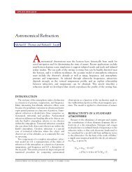
Single-chip<br />
package<br />
Subsystem<br />
chassis<br />
electronic circuitry and categorize electronic packaging<br />
requirements. Each level of packaging provides similar<br />
functions but has a distinct purpose and design.<br />
Device packaging protects the integrated circuit<br />
from corrosion and dissipates heat, creating a component<br />
with an electrical interface and mechanical support<br />
for installation and testing. The printed wiring<br />
board or substrate provides support and interconnection<br />
of the device packages to create electronic subfunctions<br />
suitable for higher-level testing. Box-level<br />
packaging allows for electronic interconnection between<br />
the circuit substrates, and performs housing and<br />
interfacing (such as connectors or keyboards) to the<br />
outside world. Partitioning of the electronic system is<br />
a process that breaks down the complete electronic<br />
circuit into these different levels. The breakdown considers<br />
many factors. This process requires an understanding<br />
of the circuit and its subfunctions, component<br />
and assembly availability, application requirements, as<br />
well as development and testing needs.<br />
Meeting performance requirements is foremost in<br />
electronic packaging. Factors such as signal speed, noise<br />
sensitivity, and electromagnetic interference often dictate<br />
the approach to packaging. Signal speed may require<br />
substrates with a low dielectric constant or impedance<br />
matching. Noisy circuits and circuits that<br />
generate electromagnetic interference may hamper the<br />
proper functioning of adjacent circuits and may need<br />
to be separated from other sensitive circuits by shielding<br />
the device or filtering the power and signal lines. 1<br />
These design considerations often dictate component<br />
Die<br />
MCM<br />
MODERN ELECTRONIC PACKAGING TECHNOLOGY<br />
placement, material choices, and<br />
space allocation.<br />
Incorporation of off-the-shelf<br />
assemblies into the product drives<br />
many packaging decisions. Such<br />
assemblies perform crucial functions<br />
and have their own electrical<br />
and mechanical interfaces. There<br />
may be many electronic, optical,<br />
and mechanical subassemblies to be<br />
incorporated into an assembly, for<br />
example, power supplies, chargecoupled<br />
device cameras, disk<br />
drives, card guides, card cages, and<br />
connectors. For optimum performance,<br />
these subassemblies usually<br />
require exacting design considerations<br />
such as special mounting<br />
brackets and connectors, heat sinking,<br />
and environmental protection.<br />
Although these design factors<br />
are critical in the prototype and<br />
one-of-a-kind hardware that <strong>APL</strong><br />
designs and builds, commercial and<br />
military electronics may have addi-<br />
tional life cycle and consumer appeal issues. Life cycle<br />
issues such as maintainability and testability must be<br />
accommodated. Ergonomics and visual appeal are high<br />
priorities in many consumer electronic products. Finally,<br />
and usually most importantly, the packaging design<br />
must fall within the cost and schedule constraints of the<br />
product.<br />
<strong>Packaging</strong> Reliability<br />
Reliable packaging begins in the design stage. At<br />
this point, the packaging engineer must consider the<br />
potential for thermal, mechanical, and corrosion problems<br />
and determine the best method to minimize their<br />
effects.<br />
Heat is a by-product of the circuit’s function that<br />
raises component temperature and can reduce its reliability.<br />
This temperature increase is an internally generated<br />
stress that must be accounted for in the package<br />
design. Below some threshold, elevated junction temperature<br />
has little effect on the life of a part, but above<br />
that threshold, component life shortens exponentially<br />
with increasing temperature. Thresholds range from<br />
100 to 150°C, 2 depending on the expected product<br />
lifetime, circuit design, and materials. Hence, the package’s<br />
ability to dissipate the device’s heat closely correlates<br />
to its reliability. Proper thermal package design<br />
ensures that the heat dissipation path maintains the<br />
junction temperature below the threshold value. Highpower<br />
devices may require special packaging design and<br />
materials to minimize the junction temperature.<br />
JOHNS HOPKINS <strong>APL</strong> TECHNICAL DIGEST, VOLUME 20, NUMBER 1 (1999) 23<br />
COB<br />
Figure 1. Three levels of packaging: the device is packaged into a component, the<br />
component is mounted on the board, and the board is installed into the subsystem chassis<br />
(MCM = multichip module, COB = chip-on-board).