Modern Electronic Packaging Technology - Johns Hopkins APL ...
Modern Electronic Packaging Technology - Johns Hopkins APL ...
Modern Electronic Packaging Technology - Johns Hopkins APL ...

Create successful ePaper yourself
Turn your PDF publications into a flip-book with our unique Google optimized e-Paper software.
Other issues besides testing drive<br />
the partitioning decisions. Partitioning<br />
usually accommodates the<br />
normal manufacturing sequence to<br />
minimize handling and cross-contamination.<br />
Systems may require<br />
additional volume and features to<br />
allow for repair, or they may be<br />
partitioned to minimize the amount<br />
of circuitry in an adverse environment.<br />
For example, on spacecraft,<br />
even though the sensors are exposed<br />
to the space environment,<br />
the boxes containing most of the<br />
support electronics are placed under<br />
thermal blankets to protect<br />
them from the temperature extremes<br />
and temperature cycling encountered<br />
in space.<br />
Analytical modeling is an essential<br />
tool in the partitioning and development<br />
of reliable electronic<br />
packaging designs. Modeling offers<br />
significant cost and schedule savings<br />
for complex systems, particularly<br />
those incorporating expensive<br />
and long lead-time subassemblies.<br />
Using specialized software, electrical<br />
modeling can be performed to<br />
simulate circuit performance. The<br />
mechanical and thermal behavior<br />
of the system can be modeled using<br />
finite element methods 9 during<br />
power cycling, temperature cycling,<br />
and shock and vibration testing.<br />
By doing so, problems can be<br />
identified and fixed, with minimal<br />
impact on cost and schedule, before<br />
any hardware is fabricated.<br />
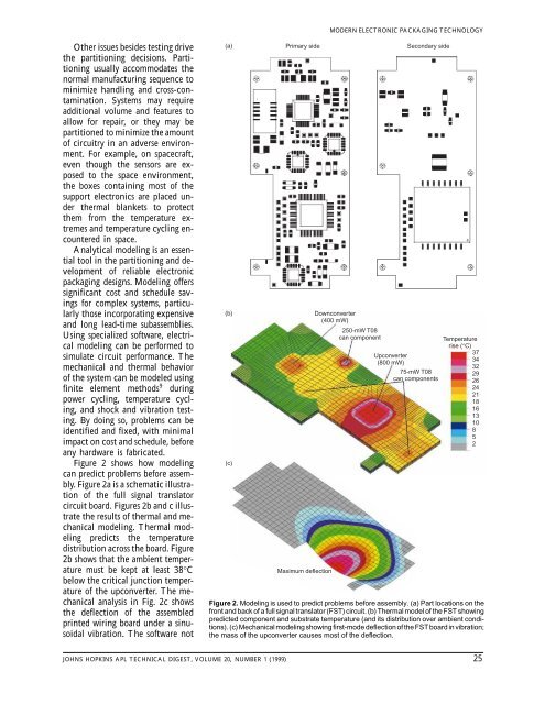
Figure 2 shows how modeling<br />
can predict problems before assembly.<br />
Figure 2a is a schematic illustration<br />
of the full signal translator<br />
circuit board. Figures 2b and c illustrate<br />
the results of thermal and mechanical<br />
modeling. Thermal modeling<br />
predicts the temperature<br />
distribution across the board. Figure<br />
2b shows that the ambient temperature<br />
must be kept at least 38°C<br />
below the critical junction temperature<br />
of the upconverter. The mechanical<br />
analysis in Fig. 2c shows<br />
the deflection of the assembled<br />
printed wiring board under a sinusoidal<br />
vibration. The software not<br />
(a)<br />
(b)<br />
(c)<br />
Primary side<br />
Maximum deflection<br />
MODERN ELECTRONIC PACKAGING TECHNOLOGY<br />
Downconverter<br />
(400 mW)<br />
250-mW T08<br />
can component<br />
Secondary side<br />
Upconverter<br />
(800 mW)<br />
75-mW T08<br />
can components<br />
Temperature<br />
rise (°C)<br />
37<br />
34<br />
32<br />
29<br />
26<br />
24<br />
21<br />
18<br />
16<br />
13<br />
10<br />
8<br />
5<br />
2<br />
Figure 2. Modeling is used to predict problems before assembly. (a) Part locations on the<br />
front and back of a full signal translator (FST) circuit. (b) Thermal model of the FST showing<br />
predicted component and substrate temperature (and its distribution over ambient conditions).<br />
(c) Mechanical modeling showing first-mode deflection of the FST board in vibration;<br />
the mass of the upconverter causes most of the deflection.<br />
JOHNS HOPKINS <strong>APL</strong> TECHNICAL DIGEST, VOLUME 20, NUMBER 1 (1999) 25