Hx1-Hx2 Manual-1.4.1 - Telos
Hx1-Hx2 Manual-1.4.1 - Telos
Hx1-Hx2 Manual-1.4.1 - Telos

Create successful ePaper yourself
Turn your PDF publications into a flip-book with our unique Google optimized e-Paper software.
TELOS <strong>Hx1</strong>/<strong>Hx2</strong><br />
Digital Hybrid Telephone Interface<br />
USER’S MANUAL<br />
<strong>Manual</strong> Version <strong>1.4.1</strong> for software version 1.4 or later<br />
15 May, 2013
<strong>Telos</strong> <strong>Hx1</strong> and <strong>Hx2</strong> <strong>Manual</strong><br />
© 2010-2013 TLS Corporation. Published by <strong>Telos</strong> Systems/TLS Corporation. All rights reserved.<br />
Trademarks<br />
<strong>Telos</strong> Systems, the <strong>Telos</strong> logo and <strong>Hx1</strong> and <strong>Hx2</strong> are trademarks of TLS Corporation. All other<br />
trademarks are the property of their respective holders.<br />
Notice<br />
All versions, claims of compatibility, trademarks, etc. of hardware and software products not made<br />
by <strong>Telos</strong> mentioned in this manual or accompanying material are informational only. <strong>Telos</strong> Systems<br />
makes no endorsement of any particular product for any purpose, nor claims any responsibility for operation<br />
or accuracy. We reserve the right to make improvements or changes in the products described<br />
in this manual which may affect the product specifications, or to revise the manual without notice.<br />
Warranty<br />
This product is covered by a two year limited warranty, the full text of which is included in this manual.<br />
Updates<br />
The operation of the <strong>Hx1</strong> and <strong>Hx2</strong> is determined largely by software. We routinely release new<br />
versions to add features and fix bugs. Check the <strong>Telos</strong> web site for the latest. We encourage you to<br />
sign-up for the email notification service offered on the site.<br />
Feedback<br />
We welcome feedback on any aspect of the <strong>Telos</strong> <strong>Hx1</strong> or <strong>Hx2</strong>, or this manual. In the past, many good<br />
ideas from users have made their way into software revisions or new products. Please contact us with<br />
your comments.<br />
Service<br />
You must contact <strong>Telos</strong> before returning any equipment for factory service. We will need the serial<br />
number, located on the back of the unit. <strong>Telos</strong> Systems will issue a Return Authorization number<br />
which must be written on the exterior of your shipping container. Please do not include cables or accessories<br />
unless specifically requested by the technical support engineer at <strong>Telos</strong>. Be sure to adequately<br />
insure your shipment for its replacement value. Packages without proper authorization may be refused.<br />
US customers please contact <strong>Telos</strong> technical support at +1-216-622-0247. All other customers should<br />
contact your local representative to make arrangements for service.<br />
We support you...<br />
By Phone / Fax:<br />
You may reach our 24/7 Support Team anytime around the clock by calling +1-216-622-0247.<br />
For billing questions or other non-emergency technical questions, call +1-216-241-7225 between 9:30<br />
AM to 6:00 PM USA Eastern Time, Monday through Friday.<br />
Our fax is +1-216-241-4103.<br />
By E-Mail:<br />
Technical support is available at Support@<strong>Telos</strong>-Systems.com.<br />
All other inquiries at Inquiry@<strong>Telos</strong>-Systems.com.<br />
Via World Wide Web:<br />
The <strong>Telos</strong> Web site has a variety of information which may be useful for product selection and support.<br />
The URL is www.<strong>Telos</strong>-Systems.com<br />
10 9 8 7 6 5 4 3 2 1
<strong>Telos</strong> Systems USA<br />
<strong>Telos</strong> Systems<br />
1241 Superior Avenue E<br />
Cleveland, OH 44114 USA<br />
+1-216-241-7225 (phone)<br />
+1-216-241-4103 (fax)<br />
+1-216-622-0247 (24/7 Technical Support)<br />
Support@<strong>Telos</strong>-Systems.com<br />
Inquiry@<strong>Telos</strong>-Systems.com<br />
Notices and Cautions<br />
This symbol, wherever it appears, alerts you to the presence<br />
of uninsulated, dangerous voltage inside the enclosure –<br />
voltage which may be sufficient to constitute a risk of shock.<br />
This symbol, wherever it appears, alerts you to important<br />
operating and maintenance instructions. Read the manual.<br />
CAUTION:<br />
THE INSTALLATION AND SERVICE INSTRUCTIONS IN THIS MANUAL ARE FOR<br />
USE BY QUALIFIED PERSONNEL ONLY. TO AVOID ELECTRIC SHOCK, DO NOT<br />
PERFORM ANY SERVICING OTHER THAN THAT CONTAINED IN THE OPERATING<br />
INSTRUCTIONS UNLESS YOU ARE QUALIFIED TO DO SO. REFER ALL SERVICING<br />
TO QUALIFIED PERSONNEL.<br />
WARNING:<br />
TO REDUCE THE RISK OF ELECTRICAL SHOCK, DO NOT EXPOSE THIS PRODUCT<br />
TO RAIN OR MOISTURE.<br />
USA CLASS A COMPUTING DEVICE INFORMATION TO USER. WARNING:<br />
This equipment generates, uses, and can radiate radio-frequency energy. If it is not installed and used<br />
as directed by this manual, it may cause interference to radio communication. This equipment complies<br />
with the limits for a Class A computing device, as specified by FCC Rules, Part 15, Subpart J, which<br />
are designed to provide reasonable protection against such interference when this type of equipment<br />
is operated in a commercial environment. Operation of this equipment in a residential area is likely<br />
to cause interference. If it does, the user will be required to eliminate the interference at the user’s<br />
expense. NOTE: Objectionable interference to TV or radio reception can occur if other devices are<br />
connected to this device without the use of shielded interconnect cables. FCC rules require the use of<br />
shielded cables.<br />
CANADA WARNING:<br />
“This digital apparatus does not exceed the Class A limits for radio noise emissions set out in the<br />
Radio Interference Regulations of the Canadian Department of Communications.”“Le present<br />
appareil numerique n’emet pas de bruits radioelectriques depassant les limites applicables aux appareils<br />
numeriques (de Class A) prescrites dans le reglement sur le brouillage radioelectrique edicte par le<br />
ministere des Communications du Canada.”
IV |<br />
Table of Contents<br />
We support you... . . . . . . . . . . . . . . . . . . . . . . . . . . . . .I<br />
A Letter from our Vice President . . . . . . . . . . . . . . . . . . . . . .VII<br />
1 Introduction 1<br />
The <strong>Hx1</strong> Hybrid . . . . . . . . . . . . . . . . . . . . . . . . . . . . . 1<br />
Purpose . . . . . . . . . . . . . . . . . . . . . . . . . . . . . . . . 1<br />
Features . . . . . . . . . . . . . . . . . . . . . . . . . . . . . . . . 2<br />
The <strong>Hx2</strong> Hybrid . . . . . . . . . . . . . . . . . . . . . . . . . . . . . 3<br />
2 Installation 5<br />
Connecting your telco lines . . . . . . . . . . . . . . . . . . . . . . . . 5<br />
Studio Audio Connections . . . . . . . . . . . . . . . . . . . . . . . . 6<br />
<strong>Hx2</strong> Internal Mix Minus . . . . . . . . . . . . . . . . . . . . . . . . . 10<br />
Input Audio Connection . . . . . . . . . . . . . . . . . . . . . . . . . 11<br />
Output Audio Connection . . . . . . . . . . . . . . . . . . . . . . . . 12<br />
Remote Control . . . . . . . . . . . . . . . . . . . . . . . . . . . . . 12<br />
Connecting your Hx to other systems and non-standard lines . . . . . . . . 14<br />
Quick Basic Test . . . . . . . . . . . . . . . . . . . . . . . . . . . . . 15<br />
Power Input and Grounding Safety . . . . . . . . . . . . . . . . . . . . 16<br />
3 Operation 17<br />
Front Panel Buttons . . . . . . . . . . . . . . . . . . . . . . . . . . . 17<br />
Line Status Display . . . . . . . . . . . . . . . . . . . . . . . . . . . 17<br />
Metering . . . . . . . . . . . . . . . . . . . . . . . . . . . . . . . . 18<br />
Basic Operation . . . . . . . . . . . . . . . . . . . . . . . . . . . . . 19<br />
4 Configuration Settings 21<br />
Rear Panel DIP Switch Control. . . . . . . . . . . . . . . . . . . . . . . 24<br />
Country Specific Settings . . . . . . . . . . . . . . . . . . . . . . . . . 27<br />
Factory Default Configuration Settings. . . . . . . . . . . . . . . . . . . 32
<strong>Telos</strong> <strong>Hx1</strong>/<strong>Hx2</strong> <strong>Manual</strong> | V<br />
5 AES I/O Option 33<br />
Installation Instructions . . . . . . . . . . . . . . . . . . . . . . . . . 33<br />
AES Channel Assignments . . . . . . . . . . . . . . . . . . . . . . . . 35<br />
Restoring an AES equipped unit to Analog Operation . . . . . . . . . . . . 35<br />
6 Troubleshooting 37<br />
On-Board Diagnostics . . . . . . . . . . . . . . . . . . . . . . . . . . 37<br />
Software Version . . . . . . . . . . . . . . . . . . . . . . . . . . . . 37<br />
DIP Switch Status . . . . . . . . . . . . . . . . . . . . . . . . . . . . 37<br />
T1 Test – 400 hz tone generation . . . . . . . . . . . . . . . . . . . . . 38<br />
T2 Test – Studio Loopback . . . . . . . . . . . . . . . . . . . . . . . . 38<br />
T3 Test – Feed Through Test . . . . . . . . . . . . . . . . . . . . . . . . 39<br />
Hardware Repairs . . . . . . . . . . . . . . . . . . . . . . . . . . . . 39<br />
7 Specifications 41<br />
8 Warranty and Application Caution 43<br />
A1 Telephone Terminology Guide A1<br />
A2 Quick Reference Guide: Rear Panel Switches A19<br />
A3 Quick Reference Guide: Internal Switches & Remote Connector pin usage A21
VI | prefaCe
A Letter from our Vice President<br />
The most compelling audio content and programming<br />
originates with the human voice. pundits, perpetrators,<br />
experts, celebrities, newsmakers, victims, moderators,<br />
and listeners - they all have opinions. Many want to be<br />
heard. and listeners want to hear them.<br />
It’s for this reason that voice quality over the challenging<br />
and changing public switched Telephone network<br />
is an engineering passion for us. <strong>Telos</strong>’ founder, the late<br />
steve Church, introduced Digital signal processing to<br />
broadcasters for the first time with the revolutionary<br />
<strong>Telos</strong> 10 phone hybrid. since that invention, steve and<br />
our engineering/development teams have brought<br />
multi-line talkshow systems, IsDn capabilities, and<br />
even large-scale T1- and prI-based talkshow systems<br />
for multiple studios.<br />
now that Voice over Ip is becoming commonplace,<br />
broadcasters benefit again from a <strong>Telos</strong> innovation -<br />
the <strong>Telos</strong> Vx talkshow system. Vx connects directly to<br />
VoIp over sIp connections and uses livewire aoIp to<br />
bring those clear caller voices right into your audio<br />
console or production workflow. Vx’s Ip connectivity is<br />
allowing broadcasters to upgrade to “HD Voice” quality<br />
for on-the-spot reports and priority listener calls.<br />
Ip connections are quickly becoming the go-to standard<br />
for broadcast remotes, studio-transmitter links,<br />
and audio content distribution. Whether for main or<br />
backup service, permanent or short-term use, <strong>Telos</strong><br />
codecs are built for professional use and jaw-dropping<br />
prefaCe | VII<br />
audio quality. The <strong>Telos</strong> Z/Ip one is designed to work<br />
well over the public Internet, and includes agile Connection<br />
Technology, enabling fast responsiveness to<br />
changing and challenging bandwidth conditions. The<br />
Z/Ip one is perfect for remote talent, with low-latency<br />
and simplified, two-button connections. Z/Ip one also<br />
affords super-reliable operation for sTl and other program<br />
links; and works over any Ip link: Ip radios, fiber,<br />
Internet, or private Wan.<br />
on the pages that follow, you’ll see tools, equipment,<br />
and systems designed to connect your listeners with<br />
compelling audio content. They’ll connect your talent<br />
with listeners, experts, and events with hardly a second<br />
thought to the amazing technology inside.<br />
Thank you for your own dedication, ideas, and comments.<br />
please tell me how you’re creating compelling<br />
content with <strong>Telos</strong>, and how we can help you do that<br />
even better!<br />
My best,<br />
Kirk Harnack<br />
Vice president and executive Director<br />
<strong>Telos</strong> systems
1 Introduction<br />
<strong>Hx1</strong> Hybrid<br />
Purpose<br />
| 1<br />
The <strong>Telos</strong> <strong>Hx1</strong> is a single digital hybrid in a 1RU 19 inch rack mount enclosure. It<br />
embodies a state of the art approach to interfacing an analog POTS (Plain Old<br />
Telephone Service) line for broadcast on-air use. The fast, precise digital automaticnulling<br />
hybrid allows smooth, natural, conversation without speakerphone-like<br />
up-cutting effects, or the audio distortion and feedback problems often experienced<br />
with lesser hybrid interface devices.<br />
The <strong>Hx1</strong> implements a number of features in the digital domain in order to enhance<br />
“real-world” performance. In particular, the hybrid includes a sophisticated automatic<br />
gain control in both the send and receive paths, a carefully implemented override<br />
ducking system, a pitch shifter for feedback reduction, and a digital dynamic EQ that<br />
keeps audio spectrally consistent from call to call.<br />
The <strong>Telos</strong> <strong>Hx1</strong> or <strong>Hx2</strong> broadcast telephone hybrids are designed to deliver pure caller<br />
audio with as little leakage from the (announcer’s) send audio as possible. <strong>Telos</strong> uses<br />
state of the art digital techniques to perform the hybrid function – the subtraction<br />
of the send audio from the received caller audio. The fully digital approach assures<br />
consistently good trans-hybrid loss, audio levels and sound quality with varying<br />
telephone line conditions.
2 | section 1<br />
Features<br />
The <strong>Telos</strong> <strong>Hx1</strong> and <strong>Hx2</strong> hybrids include many features that have historically been<br />
“add ons” or options. See the list below.<br />
♦ A high-pass filter reduces hum and low frequency noise. High- frequency<br />
noise above the telephone frequency range is also attenuated.<br />
♦ A smart digital Automatic Gain Control (AGC) smooths output levels. The<br />
gain changes occur naturally, delivering consistent levels without processing<br />
artifacts. A settable noise gate/expander on the receive path reduces phone line<br />
noise during caller pauses.<br />
♦ An adjustable override function allows ducking of the caller while the announcer<br />
is speaking.<br />
♦ Feedback is reduced by a special “pitch shifting” arrangement while echo is<br />
reduced with a basic Acoustic Echo Canceler.<br />
♦ Fixed or adaptive EQ helps to correct deficiencies in a callers telephone set or<br />
the network, resulting in a clearer, warmer, more intelligible sound from the<br />
caller.<br />
♦ Front panel metering is provided for input and output levels. EQ gain changes<br />
are displayed in real time.<br />
♦ Auto-Answer capabilities with a selectable ring count allows for unattended<br />
operation.<br />
♦ Worldwide disconnect signal detection allows use of the hybrid in different<br />
countries and with various PBXs.<br />
♦ The Hx is equipped with a complete diagnostic system for system set-up and<br />
check-out.<br />
♦ Optional AES3 support is available.<br />
♦ Built-in universal power supply and rack mount design aids in a professional<br />
installation.<br />
♦ The Hx has built-in full remote control capability, including outputs for “line<br />
ringing” and “hybrid in use” indicators.<br />
♦ <strong>Telos</strong> “Status Symbols” provide clear visual cues to operators.
<strong>Hx2</strong> Hybrid<br />
InTroDuCTIon | 3<br />
The <strong>Telos</strong> <strong>Hx2</strong> unit consists of two identical digital hybrids in a single 1RU 19 inch<br />
rack-mount enclosure.<br />
The <strong>Hx2</strong> can operate as two fully independent hybrids or be configured with an<br />
internal mix-minus to couple the two hybrids, sharing a single mix minus from the<br />
audio console and allowing callers on both hybrids to hear each other and your talent.<br />
The Hx may be controlled remotely via connections available on the unit’s remote<br />
connector (DB-9). Control functions include remote on and off control, and available<br />
status outputs include “line ringing” and “hybrid in use” open-collector indications.<br />
The remote connector allows easy direct connection to 1A2 interfaces, consoles or<br />
other remote control devices.<br />
The unit can be equipped with an optional AES3 module, which plugs into the<br />
motherboard and converts the XLR connections from analog to AES3.
2 Installation<br />
The <strong>Hx1</strong> and 2 mount in a 1RU space in a standard 19” rack. The unit generates very little heat<br />
and needs no special attention for cooling or rack placement. The unit will operate in any environment<br />
where the stirred air temperature around the unit is between 0 to 40 degrees Celsius<br />
(32 to 104 degrees Fahrenheit) with a relative humidity of 0 to 98% (non-condensing).<br />
Next installation steps are:<br />
♦ Connect your telco circuits and connect a “looped through” telephone set, if desired.<br />
♦ Connect Audio with analog connections (or AES3 if equipped).<br />
♦ Connect any needed parallel GPIO for remote control operation or to use any of the<br />
available status indications present on the rear panel DB-9 connector.<br />
♦ Power up the Hx and do a quick basic operational test using the factory settings.<br />
This installation section covers all of the above. After completing these steps you’ll be ready to<br />
move on to configuration for your specific situation.<br />
2.1 Connecting your telco lines<br />
| 5<br />
The <strong>Hx1</strong> & 2 use standard RJ-11 type “modular” telephone connectors. Only the two center<br />
pins that carry the analog line’s “tip and ring” are used. Connect the telephone line using the rear<br />
panel “LINE” jack.<br />
The Hx is designed to work with ordinary “loop start” analog phone lines, though it can operate<br />
on PBX extensions and VoIP Analog Terminal Adapters (ATA’s). Hybrid performance and<br />
system behavior on these kinds of lines may vary. If you plan to use your Hx on any of these<br />
types of lines or connect your unit to other legacy <strong>Telos</strong> systems such as the 1A2 interface or the<br />
Direct Interface Module and others, please see section 2.7.<br />
Lines that carry “Shared Line DSL” can be problematic. It’s suggested that you avoid using the<br />
Hx on lines that carry DSL, but if you must use one, be sure to use a “line splitter” or DSL filter<br />
in series with the “LINE” jack on the Hx. DSL lines have data carriers above the voice band of<br />
the circuit, usually from 25 khz to 1004 khz. DSL filters strip away the high frequency data carriers<br />
and pass on the 0-4 khz voice band and signaling. Some filters are better than others and<br />
sometimes better results can be obtained by cascading several filters, each rolling off more of the<br />
high frequency energy. On a line with DSL you might hear more “hiss” and “hash” than with a<br />
normal line.<br />
An analog phone set may be plugged into the “PHONE” jack. The telephone can be used when<br />
the Hx is “off ”. You might want to disable the telephone’s ringer if you are in a studio environment.<br />
The Hx has a “line ringing” open collector output that you can use to light lamps or<br />
strobes. See Section 2.6: the “remote” connector.<br />
The Hx has an “auto-answer” function that you can enable. See section 4.1.
6 | section 2<br />
2.2 Studio Audio Connections<br />
Mix-Minus<br />
The Hx must be fed send-to-caller audio that is free of the caller audio, a ‘mix-minus’. A mixminus<br />
is a mix of all of your audio sources that will be placed on-air (or recorded) except the<br />
caller audio – thus the mix-minus designation. The European term M-1 (mix minus one) is perhaps<br />
a clearer term. A mix-minus is also sometimes referred to as a ‘clean feed’. The important<br />
thing to remember is that the hybrid must not ‘chase its tail’ – the condition when its output<br />
makes its way somehow back to the input.<br />
Hot Tip<br />
Many hybrid installation problems are caused by an inadvertent signal path which creates a<br />
loop from the hybrid’s output back to its own input. Some consoles allow this when certain<br />
control combinations are selected by the user. In some cases, it may be as simple a mistake<br />
as assigning the hybrid to whichever bus is feeding the hybrid. This is the first place to look<br />
when strange or erratic performance is experienced. The quickest test is to bring up only the<br />
hybrid in question on the board and select a line. Dial tone should not appear on the send<br />
meter of the hybrid in question.<br />
Using a modern broadcast console’s mix-minus capability<br />
Most modern broadcast consoles have provision for multiple mix-minus busses. The best<br />
consoles allow selective feeds to the phone system. This is useful since sometimes you want only<br />
one microphone feeding the phone, but sometimes you want to three or four mics (during the<br />
morning show, for instance), and sometimes you want to play some audio piece that callers need<br />
to hear and react to such as contest sound effects, etc. Some even provide for separate ‘on-air’<br />
and ‘off line’ (recording) telephone modes.<br />
‘Making do’ with an older console<br />
Consoles made before around 1990 rarely had good support for mix-minuses, and almost never<br />
for more than one or two. With one of these oldsters, some clever improvisation is going to<br />
be needed. Here we describe a possible scenario that can be used as a starting point for your<br />
situation. We assume an older console with Program and Audition as the main busses. There<br />
is another bus of some kind that can be adapted for mix-minus application. We’ll call this the<br />
‘Utility’ bus. All sources, including the hybrid, will be assigned to Program, so the audience can<br />
hear them, as usual. We will also assign most of these sources to Utility as well, just never the<br />
fader with the hybrid’s own audio.
{<br />
Line<br />
Inputs<br />
InsTallaTIon | 7<br />
This arrangement is flexible, allowing the operator to place any or all sources in Utility for the<br />
caller to hear. In our example we have the fortunate case that the console permits the Utility bus<br />
to be fed pre-fader, letting the announcer easily use the telephone system for off-air conversations.<br />
A recorder can be attached to the Utility and hybrid outputs to record announcer + phone<br />
audio. This is often done as shown here, with each signal to a separate track. A drawback is the<br />
potential for the operator to accidentally put the hybrid in Utility, in which case it is no longer a<br />
mix-minus. To avoid this error, the signal path could be permanently disconnected by removing<br />
the summing resistors, or some such creative operation.<br />
If no bus is available to feed the Hx, you could use an external mixer that bridges the microphone<br />
inputs to achieve the same effect.<br />
The <strong>Hx2</strong> has multiple hybrids and works best if two faders can be assigned to the telephone<br />
system with two associated mix-minuses, one for each telephone line. This is probably not going<br />
to be easy with an older console. But the <strong>Hx2</strong> has an option to work with a single external mixminus<br />
by making an internal cross-connection of the hybrids. See Section 2.3 for more on this.<br />
Using a small mixer<br />
Hybrid<br />
PGM Bus<br />
To Telco<br />
Utility Bus<br />
PGM Out<br />
To Rec Ch.1<br />
To Rec Ch.2<br />
A small audio mixer is used to record interviews off the telephone line using a single hybrid.<br />
The mixer’s main bus is fed to the recording device. Both the microphone and the hybrid will be<br />
brought up on the faders so the interview can be recorded.<br />
Most small mixers (such as those made by Mackie) have one or two Aux send busses, so we will<br />
use these to feed the telephone system. We will turn up Aux for the microphone but we will<br />
make sure it is turned fully off for the each channel that has the corresponding caller audio.
8 | section 2<br />
IMPORTANT:<br />
Before connecting your Hx hybrid to any utility mixer, make sure to disable Phantom<br />
microphone power (if so equipped) from the mixer’s mic preamp. Voltage from Phantom<br />
power will damage your Hx hybrid. Factory repairs for units damaged by Phantom power will<br />
not be covered under your unit’s new-product warranty.<br />
Using a production-style console<br />
The Production-style consoles often used for TV audio will have multiple Aux send busses that<br />
can be used in a similar way to the small mixer example above. Each hybrid is sent from an Aux<br />
bus and everything the caller needs to hear is mixed into that bus, taking care to keep the hybrid<br />
itself off the bus.<br />
Phones and Remotes<br />
When on remote, to save money and hassle, calls are usually received at the studio, rather than<br />
at the remote site. In this situation, caller audio must be fed to the remote talent so that they<br />
can hear and respond to callers. Moreover, the callers need to hear the talent. In many cases, the<br />
remotes are sufficiently distant that talent cannot monitor the station for the caller feed. Even<br />
if they could, the profanity delay would be a problem, since the talent needs to hear the callers<br />
pre-delay.
InsTallaTIon | 9<br />
All perceptual codecs (such as the <strong>Telos</strong> Zephyr or X-Stream) or any IP codec, have too much<br />
delay for talent at remote locations to hear themselves via a round-trip loop. Therefore, another<br />
mix-minus is required to feed a codec.<br />
The talent hears callers via the codec return path. As before, you feed this return with mixminus:<br />
a mix of everything on the program bus minus the remote audio. As for the second half<br />
of the equation, the callers hear the talent because the remote feed is added to the telephone<br />
mix-minus bus. This is no problem if you have a set-up that permits selective assignment to the<br />
hybrid mix-minus.<br />
A problem with this arrangement is a result of a hybrid with too much leakage combined<br />
with the system delay. If the hybrid isn’t doing a good job of preventing the send audio from<br />
leaking to its output, the special remote send mix-minus is corrupted. Remember, if any of the<br />
announcer audio from the remote site is returned via the monitor feed, it will be delayed by the<br />
digital link, causing an echo effect. The <strong>Telos</strong> Hx really shows its stuff in this situation. Because<br />
it has such good trans-hybrid loss, leakage is not at all likely to be a problem. And should there<br />
ever be a problem, you can solve it by increasing the amount of ducking. See Section 4.2.<br />
Note<br />
The <strong>Telos</strong> Hx has the more common pin-outs used for three pin XLR inputs & outputs. You<br />
can easily remember the correct signals when wiring connectors using the phrase “George<br />
Washington Bridge.” Pin 1 = G = Ground, Pin 2 = W = “+” = White (typical color in mic cable, if<br />
there is no white there will be a red conductor), and Pin 3 = B = “-” = Black.
10 | section 2<br />
2.3 <strong>Hx2</strong> Internal Mix Minus<br />
The two hybrids in the <strong>Hx2</strong> unit may be configured so that a single mix-minus feed may be used<br />
for both hybrids, with each hybrid’s output fed into the other’s input internally at unity gain (so<br />
that the callers can hear each other) and sums each with the audio from the consoles mix-minus<br />
output. Only the SEND IN #1 input is used to feed both hybrids.<br />
Both hybrid outputs still function independently. The two hybrid outputs are NOT summed<br />
together, so you should provide a fader for each hybrid. The consoles mix-minus must be<br />
configured so that no hybrid’s output gets sent to its own input.<br />
The figure above illustrates which signals are combined together inside the Digital Signal<br />
Processor and routed to each connector when the <strong>Hx2</strong> internal mix-minus feature is enabled.<br />
Use this option if you only have a single mix-minus available from your console and you wish to<br />
use both hybrids to conference callers on the air. You’ll still need a fader for each hybrid output.<br />
Bit #6 in the ‘OPTIONS’ DIP switch bank controls the mix-minus feature. The internal mixminus<br />
feature is enabled when the switch is ON. The default factory setting is OFF - Disabled.
2.4 Input Audio Connection<br />
The input connection, SEND IN, has the following characteristics:<br />
♦ XLR Pin 1 = Ground,<br />
♦ XLR Pin 2 = High (Active Balanced, RF suppressed)<br />
♦ XLR Pin 3 = Low (Active Balanced, RF suppressed)<br />
♦ Bridging impedance, > 100K Ohm<br />
♦ Analog clip point at +24 dBu<br />
♦ Analog-to-Digital converter resolution of 24 bits<br />
♦ Adjustable input level from -10 to +8 dBu<br />
♦ Switchable LINE and MIC level input range<br />
InsTallaTIon | 11<br />
The unit can accommodate a line input level between -10 dbu and +8 dBu, adjustable with<br />
a trim pot on the rear panel. The input level is set to +4 dBu level from the factory. A +4dBu<br />
signal fed into the SEND IN connector should light the Yellow LED bargraph segment on the<br />
Front Panel.<br />
If more input gain is needed, turn the trimmer CLOCKWISE to increase the gain to match the<br />
operating level of the hybrid.<br />
Increasing the send level beyond a normal meter reading does not increase the level into the telco<br />
line due to the hybrid’s AGC and limiting. You will only add distortion and degrade the hybrid’s<br />
performance. There is a dip switch configuration option that applies an extra 3dB gain after the AGC,<br />
should you need more send level.<br />
Next to the input level pot is a pushbutton switch that selects between line and mic levels.<br />
When the pushbutton switch is in the LINE position (out), the input range of the SEND IN<br />
signal is –10 to +8 dBu. When the switch is in the MIC position (in), the input range of the<br />
SEND IN signal is –70 to –52 dBu.<br />
The inputs are designed to be sourced from balanced lines. Usually shielded cables have the<br />
shield wire connected only on one end (most often the input) to prevent ground loops. Older<br />
equipment with a transformer output stage may need a terminating resistor across pins 2 and 3<br />
to maintain a proper “flat” frequency response; consult the manual for your equipment for how<br />
to use it with high impedance inputs.<br />
If you are connecting a device with an unbalanced output to your Hx, connect the shield from<br />
the output of your device to pin 1 (ground) on the Hx input, and the “hot” lead from your<br />
unbalanced output to pin 2 (high) on the Hx. Depending on the device, you might also want to
12 | section 2<br />
try connecting pin 3 of the Hx input to ground, or even “floating” the ground and using only the<br />
high and low pins on the Hx. It’s also important that unbalanced lines be kept short to avoid<br />
hum and noise pickup. You’ll probably need to adjust the input gain on the Hx to match the<br />
output of your device. We also suggest that all of your audio equipment be powered from the<br />
same AC power source or circuit to prevent ground loops due to the use of multiple grounds.<br />
For complete information and suggested wiring and grounding techniques for your studio or<br />
recording workstation, please visit the support page at the <strong>Telos</strong> website:<br />
http://www.telos systems.com/support.<br />
2.5 Output Audio Connection<br />
The output connection, RCV OUT, has the following characteristics:<br />
♦ XLR Pin 1 = Ground,<br />
♦ XLR Pin 2 = High (Active Balanced, RF suppressed)<br />
♦ XLR Pin 3 = Low (Active Balanced, RF suppressed)<br />
♦ Output impedance, < 60 Ohms<br />
♦ Analog clip point at +24 dBu<br />
♦ Digital-to-Analog converter resolution of 24 bits<br />
The nominal output level is fixed at +4 dBu, with +20 dBu headroom to account for the crest<br />
factor of some audio signals.<br />
If you are connecting the output of your Hx to a device with an unbalanced input, connect the<br />
shield from your device’s unbalanced input to pin 1 (ground) on the Hx, and the “hot” lead from<br />
your device to pin 2. It’s important that unbalanced lines be kept short to avoid hum and noise<br />
pickup. We also suggest that all of your audio equipment be powered from the same AC power<br />
source or circuit to prevent ground loops due to the use of multiple grounds. For complete information<br />
on suggested wiring and grounding techniques for your studio or recording workstation,<br />
please visit the support page at the <strong>Telos</strong> website: http://www.telos-systems.com/support.<br />
2.6 Remote Control<br />
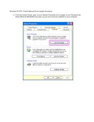
The female DB9 connector on the Back Panel provides access to control functions. Pin 1 of the<br />
DB9 connector is Ground. Pins 2 through 5 on the top row are for GPIO input signals from<br />
the remote device, while Pins 6 through 9 on the bottom row are GPIO output signals to the<br />
remote device. Two of the GPIO input pins and two of the GPIO output pins are reserved for<br />
each hybrid as follows:<br />
Hx Remote<br />
Connector<br />
GROUND<br />
Pwr 5vdc<br />
C<br />
10k<br />
D<br />
L<br />
1 6<br />
Inputs 2-5 Outputs 6-9**<br />
General internal Schematic of Hx<br />
Remote Control port<br />
** Please review manual for current limitations per GPIO outputs<br />
5<br />
9<br />
L<br />
GROUND
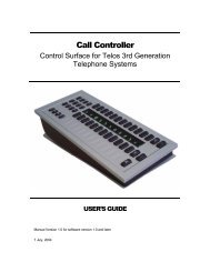
EXAMPLE<br />
INTERFACE<br />
OPTION<br />
Pin No. Function<br />
1 GPIO Ground<br />
GROUND<br />
2 GPIO IN Hybrid #1 - Hybrid ON<br />
3 GPIO IN Hybrid #1 - Hybrid OFF<br />
4 GPIO IN Hybrid #2 - Hybrid ON<br />
5 GPIO IN Hybrid #2 - Hybrid OFF<br />
6 GPIO OUT Hybrid #1 - ringing indicator<br />
7 GPIO OUT Hybrid #1 - ON/OFF status indicator<br />
8 GPIO OUT Hybrid #2 - ringing indicator<br />
** Please review manual for current limitations per<br />
9 GPIO OUT Hybrid #2 - ON/OFF status indicator<br />
GPIO outputs<br />
Input Characteristics<br />
** Please review manual for current limitations per GPIO ** outputs Please review manual for current limitations per GP<br />
InsTallaTIon | 13<br />
♦ The GPIO inputs are designed to be universal. They accept either a voltage source up<br />
to 24VDC, or a closure to ground, which may be provided by switches, relays, or logic<br />
outputs. In the latter case either ‘totem-pole’ or open-collector will work. The inputs are<br />
active low.<br />
♦ A built-in 10k Ohm pull up resistor is provided.<br />
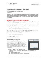
Output Characteristics<br />
♦ Open-collector to ground.<br />
5<br />
9<br />
C<br />
Control Port<br />
6<br />
1<br />
Value = As Needed<br />
R (optional)<br />
GROUND<br />
Inputs 2-5 Outputs 6-9**<br />
Ext PSU’s<br />
GROUND<br />
imax = 400 mA**<br />
Ext PSU. +5 to 24 VDC<br />
Control Port<br />
5 - 24 VDC Relay 6 Ext PSU’s<br />
GROUND<br />
Aromat or Omron Dip<br />
Relay works good<br />
A typical wiring example for an<br />
external ringing indicator<br />
Use an external PSU and tie the<br />
ground of PSU to pin 1 of HX’s<br />
Remote Port<br />
♦ These will require a pull-up resistor to drive TTL-style logic inputs. Most equipment has<br />
the pull-up built into the input, but if there is no pull-up, you’ll have to add one, connecting<br />
it from the output pin to a +5V source. An appropriate value is 2.2K Ohms. The<br />
diagram above provides a sample circuit.<br />
♦ Sink (pull-down) current must be limited to 400mA maximum per output with total<br />
output restricted to 1 amp (250 mA each output if all four will be used).<br />
Value = As Needed<br />
imax = 400 mA**<br />
Use to control a<br />
R (optional) light/strobe/etc.<br />
Contact Closure Out<br />
The GPIO output pins can be used to provide status information to other devices or warning<br />
lamps. Outputs are available to indicate “hybrid in use” and “line ringing”.<br />
5<br />
EXAMPLE<br />
INTERFACE<br />
OPTION<br />
9<br />
D<br />
5<br />
9<br />
GROUND<br />
** Please review manual for current limitations per<br />
GPIO outputs<br />
C<br />
1<br />
5<br />
Inputs 2-5 Outputs 6-9**<br />
9<br />
D<br />
Ext PSU. +5<br />
Use an externa<br />
ground of PSU<br />
Remote Port<br />
5<br />
Con<br />
A typical wiring<br />
external ringin
14 | section 2<br />
2.7 Connecting Your Hx to other systems and non-standard lines<br />
We know that you’re creative and that we couldn’t hope to address every possible situation that<br />
you face, and armed with a little knowledge about how the Hx works internally, you should be<br />
successful with most applications of the Hx.<br />
In short: The Hx will operate on anything that electrically “looks like a POTS telephone line”.<br />
You can connect the Hx to anything that is designed to run a standard Analog telephone set.<br />
It needs loop current of 15-120 ma at 12-50 volts to run its line interface chip. The chip provides<br />
telephone line audio and line signaling status (on hook/off hook/ringing/loop drop, etc) to<br />
the processor to control the unit. If loop current isn’t present, you’ll have no audio and the Hx<br />
will simply hang up. This is correct behavior.<br />
Connect to PBX’s and VoIP Analog Terminal Adapters (ATA’s)<br />
When connecting to VoIP ATA’s or PBX station ports, and even telephone company provided<br />
“pair gain” systems and channel banks, sometimes things can be a little different.<br />
Odd voltages, strange feature implementations and other issues can cause problems with audio<br />
performance and produce weird behavior. Fortunately these kinds of interfaces keep getting<br />
better, meaning that the Hx will probably “just work”, with a few possible exceptions.<br />
The most common issue is likely to be what we call disconnect supervision: that is “what the<br />
line does when the caller on the line has hung up”. Disconnect supervision is especially important<br />
if you intend to use the auto-answer feature!<br />
When an “on-air” connected call drops, a wide range of things might happen:<br />
♦ Most PBX’s will simply drop the audio from the outside line and perhaps send a fast<br />
busy (or reorder) tone. The Hx will stay off hook until you manually drop it unless you’ve<br />
set the Call Progress Tone Disconnect to disconnect after hearing reorder tone with the<br />
internal dip switches.<br />
♦ Some PBX’s will send a momentary loop current interruption that will cause the Hx to<br />
release from the line (the desired behavior. Congratulations! You’re a winner!) We’ve had<br />
good luck with PBX’s from Avaya (Larger systems). EON/Cortelco, NEC and station<br />
disconnect supervision can be enabled in Mitel digital PBX’s though it is not by default.<br />
Most telephone company central office lines do support Calling Party Control (CPC) or<br />
loop current interruption based disconnect.<br />
♦ Most ATA’s used by VoIP providers will simply play you reorder (fast busy) tone. Most<br />
are capable of sending the CPC loop current interruption signal, though many have this<br />
feature disabled by default. It can usually be turned on through the web interface on the<br />
unit. The best ones that we’ve seen are units made by Cisco/Linksys and Sipura.<br />
♦ Some Foreign Exchange or ‘choke’ lines will not pass the CPC signal and the line will go<br />
silent or to dial tone, a reorder, or even a recorded message. This is mainly a function of<br />
circuit design and the selection of central office equipment by the telephone company.<br />
Connect to a <strong>Telos</strong> 1A2 Interface<br />
Our earlier products, like our classic 1A2 interface didn’t support disconnect supervision<br />
for callers “on air”. When using the Hx with a 1A2 interface, all features will work normally<br />
though a caller selected to be “on air” who hangs up will cause the Hx to release the line (or “go<br />
on-hook”). Audio is muted because the Hx has disconnected the line. The lamp on the switch
InsTallaTIon | 15<br />
console and any key phones will remain lit until the line is “dropped” by the user.<br />
You can easily build a control cable to go between the 1A2 interface and the Hx that connects<br />
the on, off and ground signals. Then plug your analog line into the “main” (hybrid #1) or “conf ”<br />
(hybrid #2) jack on the 1A2 interface, as appropriate.<br />
1A2 Interface DB-9 PIN Hx Hybrid DB-9 PIN<br />
5 (#1 hybrid off) 3<br />
9 (#1 hybrid on) 2<br />
6 (Ground) 1<br />
4 (#2 hybrid off) 5<br />
3 (#2 hybrid on) 4<br />
Connect to a <strong>Telos</strong> Direct Interface Module<br />
Using the Hx, or any hybrid supporting disconnect supervision with the Direct Interface<br />
Module (DIM) requires an external source of loop current. The DIM provides only a “dry”<br />
transformer audio feed which worked well with the simpler hybrids of the time. Visit the <strong>Telos</strong><br />
website or contact support for several options that will allow you to use the Hx with the DIM.<br />
Connect to other systems? Contact <strong>Telos</strong> Support<br />
<strong>Telos</strong> collects and shares what we learn about “real world” telephony with our customers. Our<br />
customers come up with creative ways to use our products and often create elegant solutions for<br />
unusual problems. We’d appreciate hearing about your successes and challenges to share with<br />
other colleagues and friends. We’re also interested in your experiences with service providers and<br />
telecom systems and equipment vendors.<br />
2.8 Quick Basic Test<br />
It’s all connected, Now it’s time to check for signs of life!<br />
First, Power the unit up and watch it complete its self test.<br />
If the phone line is connected properly, a “dot” should be present on the display, if a minus “-” is<br />
displayed the Hx does not detect the line voltage on the idle POTS line. Check your wiring!<br />
If your Hx is directly connected to a phone line, press the [ON] key and dial tone should be<br />
present on the Hx’s output and RCV bargraph.<br />
If you have your Hx connected to a 1A2 interface, press a line key on the switch console. The<br />
Hx should come on and dial tone should be heard on it’s output and seen on the RCV bargraph.<br />
Pressing the ‘drop’ key should release it, and the ‘hold’ key should put the line on hold. The<br />
display will show a minus “-” to indicate that a line is not detected. This is because the 1A2<br />
interface only routes a line to the Hx when one is selected by the user, and is present.<br />
Verify correct mix minus operation at this point by noting that the RCV bargraph shows the<br />
dial tone at at a nominal level, and that the SND bargraph shows only the microphone or audio<br />
present on the device feeding the Hx SEND IN. The goal of a proper mix minus is to prevent<br />
the hybrid from ‘hearing itself ’.
16 | section 2<br />
2.9 Power Input and Grounding Safety<br />
2.9 Power Input and Grounding Safety. The AC input connects mains power to the unit with a<br />
standard IEC power cord. The power supply has a universal AC input, accepting a range from<br />
100 to 240 VAC, 50-60 Hz, at 0.15 - 0. 075 Amps.<br />
IMPORTANT SAFETY INFORMATION<br />
Surge Protection<br />
Precautions should be taken to prevent damage caused by power surges.<br />
WARNING<br />
The <strong>Hx1</strong> and <strong>Hx2</strong> use a universal-input power supply, which has an internal fuse. Hazardous<br />
voltages may still be present on some of the primary parts even when the fuse has blown.<br />
The power cord is the primary disconnect mechanism. Mains power should be near the equipment<br />
and easily accessible. The unit should not be positioned such that access to the power cord<br />
is impaired. If the unit is incorporated into a rack, an easily accessible safety disconnect device<br />
should be included in the rack design.<br />
Grounding<br />
This equipment is designed to be operated from a power source which includes a third grounding<br />
connection in addition to the power leads. Do not defeat this safety feature. In addition to<br />
creating a potentially hazardous situation, defeating this safety ground will prevent the internal<br />
line noise filter from functioning.<br />
Should you replace the power supply module in the future, be sure to re-connect the safety<br />
ground wires as shown in the illustration below.<br />
Inside the chassis near the power inlet is a ground stud. The ground wire from the power inlet<br />
is attached to the ground stud with a star washer on either side of the wire terminal. (See above<br />
figure). A nut is used to independently tighten the inlet ground wire to the chassis. Next, the<br />
ground wire from the power supply is fastened to the ground stud with a star washer on either<br />
side of the wire terminal. An additional nut is fastened to the top of the ground stud.
3 operation<br />
3.1 Front Panel Buttons<br />
There is a column of three pushbutton switches on the Front Panel for each hybrid.<br />
Hybrid ON<br />
Caller ON-HOLD<br />
Hybrid OFF<br />
3.2 Line Status Display<br />
| 17<br />
The Line Status display on the Front Panel shows the state of the phone line in iconic form. The<br />
Status Symbol icons displayed on the LED matrix in normal operating mode are as follows:<br />
Line is ready for incoming or outgoing calls<br />
Line not detected<br />
Line is ringing
18 | section 3<br />
Call is ON-AIR<br />
Call is ON-HOLD<br />
If the Line Status display indicates “Line not detected” after power-up, the telephone line is not<br />
connected to the LINE jack on the back Panel, or line voltage is not detected. Check your wiring<br />
and verify that dial tone is present on the line. This function is not compatible with ground<br />
start lines or trunks as these do not have loop current or voltage present until the line has been<br />
grounded momentarily or is ringing.<br />
3.3 Metering<br />
Each hybrid has its own SND and RCV meters to simultaneously display the studio input audio<br />
level, as well as the output level of the caller. Set the input level pot so that 0dbu on your console<br />
causes the Hx to display a yellow bar on the SND bargraph. The meter displays audio before any<br />
processing.<br />
The output meter indicates audio levels after all processing and EQ. It’s also useful for troubleshooting<br />
mix minus and other audio issues. A yellow bar corresponds to +4dbu at the audio<br />
output. The nominal output level is fixed at +4dbu.<br />
Each hybrid also has a pair of EQ meters which show that amount of gain adjustment applied<br />
to the incoming caller audio in HI and LO frequency bands. When the DDEQ feature is<br />
disabled via the Back Panel DIP switch settings, nothing will appear on the EQ HI and EQ<br />
LO bar graphs.
3.4 Basic Operation<br />
operaTIon | 19<br />
You can use a telephone set to either dial an outgoing call or to talk to an incoming caller before<br />
they are switched to the hybrid.<br />
When a call is ringing-in, the line status icon will display expanding concentric squares. Push<br />
the button to answer it directly on the hybrid or use the telephone set to speak with the<br />
caller. You can move the call from the telephone to the hybrid by pressing the button. The<br />
telephone set will be disconnected.<br />
When a call is taken on the hybrid, a brief mute/adapt period provides an opportunity for the<br />
system to adapt to the line before the call goes on the air. The caller hears a “noise burst” to alert<br />
him that he’s on the air but the noise burst isn’t heard by the audience as the output is muted<br />
while the noise is being sent. While the caller is on the hybrid, the hybrid continuously adapts<br />
to telephone line characteristics.<br />
Press the button to return the call to the telephone handset and disconnect it from the<br />
hybrid. Hang up the phone if you want to drop the call.<br />
When a call is active on the hybrid, pressing the button mutes the receive audio, but keeps<br />
the call active on the hybrid. The caller hears send audio while waiting on hold and the unit will<br />
disconnect if the held caller hangs up or is disconnected for any reason. When a call is on hold<br />
and you press the button, the caller audio is restored. The caller will hear the adapt noise/<br />
tone, about half the length of when you press the button from any other condition. Thus,<br />
one purpose of the Hold function is to allow a “pre-adaption” to the telephone line and a quick<br />
take of it later.
4 Configuration settings<br />
| 21<br />
Configuration of the Hx is done via DIP switch settings. There’s a quick reference guide in the<br />
back of this book that lists the remote connector pin numbers and all of the available configuration<br />
options and their switch settings. You’ll probably use those two pages more than anything<br />
else in this manual. There’s also a diagram at the end of this section that shows inputs, outputs,<br />
controls and metering points. A picture is worth a thousand words, maybe more when you’re in<br />
a hurry.<br />
Before we lose you to the “quick reference guide” we should point out that here we provide the<br />
details that you might need to set up your Hx most effectively. If this is your first Hx, a few<br />
minutes with this section will help you determine which features will help you in your particular<br />
application.<br />
Send Audio Processing<br />
The <strong>Hx1</strong> and <strong>Hx2</strong> hybrid’s send-to-caller audio processing consists of the following functions:<br />
♦ Sample rate conversion<br />
♦ High-pass filter<br />
♦ Anti-Feedback - the “pitch” shifter and Acoustic Echo Canceler<br />
♦ Send AGC/Limiter<br />
Sample Rate Conversion<br />
AES and analog input sources are sample rate converted to the hybrid’s internal sampling rate<br />
of 8 KHz.<br />
High-Pass filter<br />
A high pass filter with a 300 Hz break frequency improves hybrid performance and enhances<br />
intelligibility by removing unnecessary low frequencies from the input audio. This function is<br />
always enabled.<br />
Send Automatic Gain Control / Limiter<br />
The AGC helps maintain consistent audio levels to the caller. This function is always enabled. At<br />
moderate levels it is ‘AGC-like’ while at higher peak levels it is more ‘limiter-like’. In addition<br />
to making levels more consistent to callers, it performs the protection limiting required to meet<br />
Telecom regulatory requirements.<br />
Feedback Reduction<br />
The HX has a simple Acoustic Echo Canceler (AEC) that improves feedback performance and<br />
cancels echo caused by ‘speaker to mike’ acoustic coupling. The HX also uses a ‘frequency shifter’<br />
(a <strong>Telos</strong> innovation) that inserts a small, unnoticeable, shift in frequency to the send audio to<br />
prevent feedback buildup when the system is used with open speakers.
22 | section 4<br />
Receive Audio Processing<br />
The <strong>Hx1</strong> and <strong>Hx2</strong> hybrid’s receive audio processing consists of the following functions:<br />
♦ High-pass “hum” filter<br />
♦ Adaptive Echo Cancellation<br />
♦ Automatic Gain Control<br />
♦ Noise Gate<br />
♦ Digital Dynamic Equalization<br />
♦ Sample rate conversion<br />
High-pass “hum” Filter<br />
This filter removes hum and other unwanted low frequency noise from the caller audio. This<br />
filter has a break frequency of 100 Hz.<br />
Adaptive Echo Cancellation<br />
An adaptive filter removes studio send audio from the received caller audio. It adapts continuously<br />
and naturally.<br />
Receive Automatic Gain Control<br />
The Hx’s smart gated AGC improves the consistency of the caller’s audio level delivered to the<br />
studio console, without audible processing ‘artifacts’ .<br />
An important additional feature of this AGC is that it is cross-coupled to other sections of the<br />
hybrids and can therefore reliably distinguish between caller audio and hybrid leakage. This<br />
allows a more aggressive gain control for bringing up low-level callers while still preserving<br />
excellent hybrid performance.<br />
Noise Gate<br />
Turning on the noise gate enables the built-in downward expander. The downward expander<br />
reduces low level line noise when no caller audio is present and reduces low level leakage. This<br />
function is cross-coupled with the AGC and the ducking system.<br />
Digital Dynamic Equalizer<br />
Telephone audio frequency response varies widely as many different factors can affect it (we’ve<br />
measured the response on a number of calls and the results were very revealing). Consequently,<br />
some form of receive equalization is desirable. The Hx’s Digital Dynamic EQ process is the<br />
most sophisticated equalizer available in a broadcast telephone interface. All processing is<br />
performed in the digital domain. The Receive EQ settings control the type of equalization<br />
applied to the receive telephone audio as follows:<br />
♦ Off - The caller audio is passed without modification.<br />
♦ Fixed - This is a simple manual equalizer.<br />
♦ Adaptive (Digital Dynamic) - This is a three band dynamic equalizer. We’ve chosen<br />
frequency breakpoints, time constants, and other characteristics to optimize the tonal<br />
quality of varied telephone callers. You set desired ‘target levels’ to customize the callers<br />
spectral characteristics, which are maintained from call to call.<br />
♦ Adaptive + Fixed - This mode separately adds a fixed amount of additional gain to the<br />
high and low frequency bands of the three band dynamic equalizer.
Ducking System<br />
The ducking function serves several purposes:<br />
ConfIGuraTIon seTTInGs | 23<br />
♦ Provides “aesthetic” control over the caller that many programmers prefer. Allows the<br />
announcer to “override” the caller in a way that sounds natural and appropriate.<br />
♦ Reduces feedback when the Hx is used like a speakerphone in an “open<br />
loudspeaker’”situation.<br />
♦ Dynamically improves effective trans-hybrid loss to reduce leakage, when necessary.<br />
When used, the Hx inserts a controlled loss (ducking) into whichever audio path (send or<br />
receive) is not active at the moment. When the caller is speaking, this loss is inserted in the<br />
announcer path, and when the announcer is speaking, the caller gain is reduced. The effect<br />
is “seesaw-like”. Normally, the gain reduction is symmetrical, but, if Feedback Reduction is<br />
enabled, the hybrid will have more ducking in the announcer-to-caller direction.<br />
You’ll probably need more ducking when using an open loudspeaker. As noted above, ducking<br />
helps prevent feedback and reduces echo returned to the caller.<br />
You can select how much of this effect you prefer, from Half Duplex, which makes the hybrid<br />
operate like a ‘one-way-at-a-time’ speakerphone, to Full Duplex (0dB) which disables ducking<br />
altogether. The default is –6 dB.<br />
Signal Flow and Audio Processing<br />
The above figure illustrates the signal processing chain in both the SEND input to the caller, as<br />
well as the caller receive to RCV output path. The Ducker is involved in both processing paths.<br />
The figure also shows which processing stages that you can adjust via the SETTINGS and OP-<br />
TIONS bank of DIP switches in the rear of the hybrid unit. See Section 4.1 for further details<br />
regarding the DIP switch settings.
24 | section 4<br />
4.1 Rear Panel DIP Switch Control<br />
On the rear panel of the <strong>Hx1</strong> and <strong>Hx2</strong> chassis there are two banks of DIP switches labeled<br />
SETTINGS and OPTIONS. The SETTINGS bank of DIP switches (SW1) allows you to<br />
control the operational levels of various signal processing stages of the hybrid unit. The OP-<br />
TIONS bank of DIP switches (SW2) allows you to configure the operation of various features<br />
of the hybrid. The two tables below show how the individual DIP switches are allocated on<br />
each bank.<br />
SETTINGS Function<br />
Bits 1 and 2 EQ LO, fixed dB gain adjustment<br />
Bits 3 and 4 EQ HI, fixed dB gain adjustment<br />
Bits 5 and 6 Ducker dB gain adjustment<br />
Bits 7 and 8 AGC and Noise Gate settings<br />
OPTIONS Function<br />
Bits 1 and 2 DDEQ configuration<br />
Bits 3 and 4 Auto-Answer configuration<br />
Bit 5 Send gain to phone<br />
Bit 6 <strong>Hx2</strong> internal mix-minus enable<br />
Bit 7 Feedback Reduction enabled<br />
Bit 8 Reserved<br />
Dynamic Digital Equalization Configuration settings<br />
OPTIONS Bits #1 and #2 control the overall operation of the DDEQ processing function. You<br />
can select between OFF, Fixed EQ, Adaptive EQ, or Adaptive + Fixed EQ using the following<br />
bit settings:<br />
OPTIONS<br />
Bit 1 Bit 2 Configuration Setting Value<br />
OFF OFF DDEQ feature is turned OFF<br />
OFF ON Fixed EQ mode (Use SETTING Bits #1, 2, 3, 4 to<br />
set the levels)<br />
ON OFF Adaptive EQ mode [Factory Default]
Bit 1 Bit 2 Configuration Setting Value<br />
ConfIGuraTIon seTTInGs | 25<br />
ON ON Adapt + Fixed EQ (Use SETTING Bits #1, 2, 3, 4 to<br />
set the Fixed levels)<br />
You can separately specify the level of adjustment in the EQ HI and EQ LO frequency bands<br />
when the DDEQ mode is configured for Fixed EQ mode. SETTINGS Bits #1 and #2 control<br />
the dB adjustment for the EQ HI band, and Bits #3 and #4 control the dB adjustment for the<br />
EQ LO band as follows:<br />
SETTINGS<br />
Bit 1 Bit 2 Configuration Setting Value<br />
OFF OFF 0 dB adjustment, EQ LO [Factory Default]<br />
OFF ON +2 dB adjustment, EQ LO<br />
ON OFF +4 dB adjustment, EQ LO<br />
ON ON +6 dB adjustment, EQ LO<br />
SETTINGS<br />
Bit 3 Bit 4 Configuration Setting Value<br />
OFF OFF 0 dB adjustment, EQ HI [Factory Default]<br />
OFF ON +2 dB adjustment, EQ HI<br />
ON OFF +4 dB adjustment, EQ HI<br />
ON ON +6 dB adjustment, EQ HI<br />
You are encouraged to try varying levels of EQ boost to make your telephone audio warmer and<br />
clearer. Our factory default settings should be considered a safe starting point. Because tastes<br />
and situations differ, we don’t presume to make those choices for you. Our testing does suggest<br />
that utilizing the full 6 db boost works well in most cases, dramatically enhancing telephone<br />
audio.<br />
We suggest that you set up your phones like you would any other audio processing device: adjust<br />
and listen critically and repeat this process until you’re satisfied.<br />
Ducker Configuration settings<br />
SETTINGS Bits #5 and #6 control the overall operation of the Ducker processing function.<br />
You can select between full-duplex (no ducking), -6 dB, -12 dB, or half-duplex (one way at a<br />
time) using the following bit settings:<br />
SETTINGS<br />
Bit 5 Bit 6 Configuration Setting Value<br />
OFF OFF Full Duplex (no attenutation)<br />
OFF ON -6 dB attenuation [Factory Default]<br />
ON OFF -12 dB attenuation<br />
ON ON Half Duplex
26 | section 4<br />
Receive AGC and Noise Gate Configuration settings<br />
SETTINGS Bits #7 and #8 jointly control the operation of the receive AGC and Noise Gate<br />
processing functions. You can select how aggressively low level signals are brought up to the<br />
nominal (+4 dBu) level using the following bit settings:<br />
SETTINGS<br />
Bit 7 Bit 8 Configuration Setting Value<br />
OFF OFF Phone AGC = OFF, Noise Gate = OFF<br />
OFF ON Phone AGC = 1/2 Full, Noise Gate = OFF<br />
ON OFF Phone AGC = Full Noise Gate = OFF [Factory Default]<br />
ON ON Phone AGC = Full Noise Gate = Normal<br />
Auto-Answer Configuration settings<br />
OPTIONS Bits #3 and #4 jointly control the operation of the Auto-Answer feature of the<br />
hybrid. You can select between turning the feature off, or set the number of rings before the<br />
incoming call is answered and the placed on air as follows:<br />
OPTIONS<br />
Bit 3 Bit 4 Configuration Setting Value<br />
OFF OFF Auto-Answer = OFF, [Factory Default]<br />
OFF ON Auto-Answer = ON, Auto-answer after first ring<br />
ON OFF Auto-Answer = ON Auto-answer after third ring<br />
ON ON Auto-Answer = ON Auto-answer after eighth ring<br />
Send extra gain to caller configuration setting<br />
The <strong>Hx1</strong> and <strong>Hx2</strong> hybrid units have been designed to send a -9 dBu average level to the<br />
telephone line, to meet the USA’s FCC regulations. OPTION Bit #5 adds 3dB of gain to the<br />
send level heard by the caller. This should only be used when the hybrid is connected to a PBX<br />
or in countries outside of the USA that permit a higher transmit level.<br />
OPTIONS<br />
Bit 5 Configuration Setting Value<br />
OFF No additional gain is applied [Factory Default]<br />
ON +3 dB additional gain is applied to the audio sent to the caller
<strong>Hx2</strong> Internal Mix-Minus Configuration setting<br />
ConfIGuraTIon seTTInGs | 27<br />
The <strong>Hx2</strong> can operate as two independent hybrids or be configured to perform an internal mixminus<br />
between the two hybrids.<br />
OPTIONS<br />
Bit 6 Configuration Setting Value<br />
OFF Independent: Internal mix-minus is disabled. [Factory Default]<br />
ON Coupled: Internal mix-minus is enabled.<br />
Feedback Reduction enable<br />
The Hx 1 and <strong>Hx2</strong> has an optional Acoustic Echo Canceler in the Studio send path. This can be<br />
used when there is acoustic coupling between a loudspeaker connected to the hybrid output and<br />
a microphone connected to the input. Enabling feedback reduction also causes the ducker to<br />
insert more loss into the announcer-to-caller direction when the caller is dominant.<br />
OPTIONS<br />
Bit 7 Configuration Setting Value<br />
OFF Acoustic Echo Canceler is disabled [Factory Default]<br />
ON Acoustic Echo Canceler is enabled (use in “open speaker” situation)<br />
Reserved bit<br />
OPTIONS Bit #8 is set aside as RESERVED for future use.<br />
OPTIONS<br />
Bit #8 Configuration Setting Value<br />
OFF Reserved for future use [Factory Default]<br />
ON Not Recommended<br />
4.3 Country Specific Configuration Settings<br />
There is a third bank of DIP switches located inside the Hx chassis. This switch bank is used to<br />
set country specific voltage and line impedance settings and to set the Call Progress Tone to be<br />
detected if Call Progress Tone Disconnect is used.<br />
The Factory Default setting is all 8 bits set to the OFF position (labeled OPEN on the<br />
switch). This default configuration is set for operation within the United States and Canada<br />
(North American telephone line characteristics, and the ‘precise’ dial-tone signal for Call<br />
Progress Tone Disconnect).<br />
You must remove the top cover of the chassis to gain access to third bank of DIP switches<br />
located on the Hx motherboard. The chassis cover should only be removed by a qualified<br />
technician. AC power must be disconnected prior to removing the cover.
28 | section 4<br />
The internal DIP switch bank is divided up into two subsets of 4 switches each:<br />
♦ Bits #1 through 4 configure the Hx’s telephone interface circuitry to match the telephone<br />
line impedance and voltage characteristics of the country where the hybrid is used.<br />
♦ Bits #5 through 8 configure Call Progress Tone Detection to match the call progress<br />
tones used by various countries or central office switches. Call progress tones (Dial tone,<br />
busy tone, etc) can be used to make the Hx disconnect when loop current signaling is not<br />
available or is unreliable. Call Progress Tone Disconnect is active only on Auto-Answered<br />
incoming calls to prevent undesired disconnections. It may be disabled if the feature<br />
causes problems in your application. See internal DIP switch settings table below.<br />
Table 1 lists what telephone network characteristics are being selected by Bits #1 through 4.<br />
Table 2 lists the Call Progress Tone Detection characteristics being selected by Bits #5 through 8.<br />
Table 3 lists the recommended DIP switch settings for each country. Reorder tone is a “fast<br />
busy” signal often used to indicate network congestion or error conditions.<br />
Table 1 - Internal DIP Switch bank<br />
Bit 1 Bit 2 Bit 3 Bit 4 Telephone Network<br />
OFF OFF OFF OFF USA, Canada<br />
OFF OFF OFF ON Japan, low voltage networks<br />
OFF OFF ON OFF FCC compliant countries<br />
OFF OFF ON ON CRT21, Europe (real line impedance)<br />
OFF ON OFF OFF Custom country configuration<br />
OFF ON OFF ON Custom country configuration<br />
OFF ON ON OFF Custom country configuration<br />
OFF ON ON ON Europe (complex line impedance)<br />
ON OFF OFF OFF Custom country configuration
Bit 1 Bit 2 Bit 3 Bit 4 Telephone Network<br />
ON OFF OFF ON Custom country configuration<br />
ON OFF ON OFF Custom country configuration<br />
ON OFF ON ON Reserved for future use<br />
ON ON OFF OFF Reserved<br />
ON ON OFF ON Reserved<br />
ON ON ON OFF Reserved<br />
ON ON ON ON Reserved<br />
TABLE 2 – Internal DIP Switch bank<br />
Bit 5 Bit 6 Bit 7 Bit 8 CPTD Signal characteristics<br />
OFF OFF OFF OFF US dial tone<br />
OFF OFF OFF ON US re-order signal<br />
OFF OFF ON OFF WORLD, single freq. Dial tone<br />
OFF OFF ON ON WORLD, Re-order, ON=155 - 550, OFF=155 – 550 msec<br />
ConfIGuraTIon seTTInGs | 29<br />
OFF ON OFF OFF WORLD, Re-order, ON=250 - 1200, OFF=250 – 1200 msec<br />
OFF ON OFF ON WORLD, multi-tone dial tone<br />
OFF ON ON OFF WORLD, multi-tone dial tone<br />
OFF ON ON ON WORLD, pulse dial tone, ON=150 - 350, OFF=450 – 1100 msec<br />
ON OFF OFF OFF WORLD, pulse dial tone, ON=100 - 250, OFF=200 – 400 msec<br />
ON OFF OFF ON Reserved for future use<br />
ON OFF ON OFF Reserved<br />
ON OFF ON ON Reserved<br />
ON ON OFF OFF Reserved<br />
ON ON OFF ON Reserved<br />
ON ON ON OFF Reserved<br />
ON ON ON ON CPTD feature is disabled<br />
Table 3 - Recommended Internal DIP Switch for each Country<br />
Country Bit 1 Bit 2 Bit 3 Bit 4 Bit 5 Bit 6 Bit 7 Bit 8<br />
Argentina OFF OFF ON OFF OFF OFF ON OFF<br />
Australia ON OFF OFF ON OFF OFF ON ON<br />
Austria OFF OFF ON ON OFF OFF ON OFF<br />
Bahrain OFF OFF ON OFF OFF OFF ON OFF<br />
Belgium OFF OFF ON ON OFF OFF ON OFF<br />
Brazil OFF OFF OFF ON OFF OFF ON OFF<br />
Bulgaria OFF ON ON ON OFF ON ON ON
30 | section 4<br />
Country Bit 1 Bit 2 Bit 3 Bit 4 Bit 5 Bit 6 Bit 7 Bit 8<br />
Canada OFF OFF ON OFF OFF OFF OFF OFF<br />
Chile OFF OFF ON OFF OFF OFF ON OFF<br />
China OFF OFF OFF ON OFF OFF ON OFF<br />
Colombia OFF OFF ON OFF OFF OFF ON OFF<br />
Croatia OFF ON ON ON OFF ON ON ON<br />
CTR21 OFF OFF ON ON OFF OFF ON OFF<br />
Cyprus OFF ON ON ON OFF ON OFF ON<br />
Czech Repub OFF ON ON ON OFF OFF ON OFF<br />
Denmark OFF OFF ON ON OFF OFF ON ON<br />
Ecuador OFF OFF ON OFF OFF OFF ON OFF<br />
Egypt OFF OFF OFF ON OFF ON OFF OFF<br />
El Salvador OFF OFF ON OFF OFF OFF ON OFF<br />
Finland OFF OFF ON ON OFF OFF ON OFF<br />
France OFF OFF ON ON OFF ON OFF OFF<br />
Germany OFF OFF ON ON OFF OFF ON ON<br />
Greece OFF OFF ON ON OFF OFF ON OFF<br />
Guam OFF OFF ON OFF OFF OFF ON OFF<br />
Hong Kong OFF OFF ON OFF OFF OFF OFF OFF<br />
Hungary OFF OFF ON OFF OFF OFF ON ON<br />
Iceland OFF OFF ON ON OFF OFF ON OFF<br />
India OFF OFF ON OFF OFF OFF ON OFF<br />
Indonesia OFF OFF ON OFF OFF OFF ON OFF<br />
Ireland OFF OFF ON ON OFF OFF ON OFF<br />
Israel OFF OFF ON ON OFF OFF ON OFF<br />
Italy OFF OFF ON ON OFF OFF ON ON<br />
Japan OFF OFF OFF ON OFF ON OFF OFF<br />
Jordan OFF OFF OFF ON OFF OFF ON OFF<br />
Kazakhstan OFF OFF OFF ON OFF OFF ON OFF<br />
Kuwait OFF OFF ON OFF OFF OFF ON OFF<br />
Latvia OFF OFF ON ON OFF OFF ON OFF<br />
Lebanon OFF OFF ON ON OFF OFF ON OFF<br />
Luxembourg OFF OFF ON ON OFF OFF ON OFF<br />
Macao OFF OFF ON OFF OFF OFF ON OFF<br />
Malaysia OFF OFF OFF ON OFF OFF ON OFF<br />
Malta OFF OFF ON ON OFF OFF ON OFF<br />
Mexico OFF OFF ON OFF OFF OFF ON OFF<br />
Morocco OFF OFF ON ON OFF OFF ON OFF<br />
Netherlands OFF OFF ON ON OFF OFF ON ON<br />
New Zealand OFF ON ON OFF OFF OFF ON OFF<br />
Nigeria OFF OFF ON ON OFF OFF ON OFF<br />
North Korea OFF OFF ON ON OFF OFF ON OFF<br />
Norway OFF OFF ON ON OFF OFF ON OFF<br />
Oman OFF OFF OFF ON OFF OFF ON OFF
ConfIGuraTIon seTTInGs | 31<br />
Country Bit 1 Bit 2 Bit 3 Bit 4 Bit 5 Bit 6 Bit 7 Bit 8<br />
Pakistan OFF OFF OFF ON OFF OFF ON OFF<br />
Peru OFF OFF ON OFF OFF OFF z ON OFF<br />
Philippines OFF OFF OFF ON OFF OFF ON OFF<br />
Poland ON OFF OFF OFF OFF OFF ON OFF<br />
Portugal OFF OFF ON ON OFF OFF ON OFF<br />
Romania OFF OFF ON OFF OFF OFF ON OFF<br />
Russia OFF OFF OFF ON OFF OFF ON OFF<br />
Saudi Arabia OFF OFF ON OFF OFF OFF ON OFF<br />
Singapore OFF OFF ON OFF OFF OFF ON ON<br />
Slovakia OFF OFF ON OFF OFF ON ON ON<br />
Slovenia ON OFF OFF OFF OFF ON ON ON<br />
South Africa ON OFF ON OFF OFF OFF ON OFF<br />
South Korea OFF OFF ON OFF OFF OFF ON OFF<br />
Spain OFF OFF ON ON OFF OFF ON OFF<br />
Sweden OFF OFF ON ON OFF ON OFF OFF<br />
Switzerland OFF OFF ON ON OFF OFF ON OFF<br />
Syria OFF OFF OFF ON OFF OFF ON OFF<br />
Taiwan OFF OFF OFF ON ON OFF OFF OFF<br />
Thailand OFF OFF OFF ON OFF OFF ON OFF<br />
Turkey OFF OFF ON ON OFF OFF ON OFF<br />
UAE OFF OFF ON OFF OFF OFF OFF OFF<br />
United Kingdom OFF OFF ON ON OFF ON OFF ON<br />
USA OFF OFF ON OFF OFF OFF OFF OFF<br />
Yemen OFF OFF ON OFF OFF OFF ON OFF
32 | section 4<br />
Factory Default Configuration Settings<br />
These settings will work in most cases and should be considered to be a “starting point”.<br />
The following is the Factory Default Configuration for the SETTINGS, OPTIONS, and<br />
Internal Telephone Network/Call Progress Tone Detection (CPTD) DIP switches:<br />
Bit 1 Bit 2 Bit 3 Bit 4 Bit 5 Bit 6 Bit 7 Bit 8<br />
SETTINGS OFF OFF OFF OFF OFF ON ON OFF<br />
Bits 1 and 2 EQ LO, fixed dB gain adjustment => 0 dB gain<br />
Bits 3 and 4 EQ HI, fixed dB gain adjustment => 0 dB gain<br />
Bits 5 and 6 Ducker dB gain adjustment => -6 dB ducking<br />
Bits 7 and 8 AGC and Noise Gate settings => AGC is FULL, Noise Gate is OFF<br />
Bit 1 Bit 2 Bit 3 Bit 4 Bit 5 Bit 6 Bit 7 Bit 8<br />
OPTIONS ON OFF OFF OFF OFF OFF OFF OFF<br />
Bits 1 and 2 DDEQ configuration => Dynamic EQ is enabled<br />
Bits 3 and 4 Auto-Answer configuration => feature is OFF<br />
Bit 5 Send gain to phone => feature is OFF<br />
Bit 6 <strong>Hx2</strong> internal mix-minus enable => feature is OFF<br />
Bit 7 Feedback Reduction enabled => feature is OFF<br />
Bit 8 Reserved<br />
Bit 1 Bit 2 Bit 3 Bit 4 Bit 5 Bit 6 Bit 7 Bit 8<br />
INTERNAL OFF OFF OFF OFF OFF OFF OFF OFF<br />
Bits 1 through 4 Telephone Network configuration => USA, Canada<br />
Bits 5 through 8 Call Progress Tone Detection => USA dial tone
5 aes I/o opTIon<br />
5.1 Installation Instructions<br />
The <strong>Hx1</strong> and <strong>Hx2</strong> hybrid units can be purchased with the optional AES I/O module preinstalled,<br />
or as an upgrade kit to be installed in the field. The AES board Upgrade Kit [2011-<br />
00068] includes the following items:<br />
1701-00149-100 (Qty =1) AES Board assembly<br />
1308-00023-100 (Qty =2) board standoff, M3x10mm, MF<br />
1301-00077-100 (Qty =2) screw, M3x6mm Phillips Pan-Head steel zinc<br />
The following instructions explain the steps to install the AES I/O module onto the motherboard<br />
using the upgrade kit. Chassis cover removal and upgrade kit installation should only<br />
be performed by a qualified technician or engineer.<br />
1. AC power must be disconnected prior to removing the chassis cover. Remove the AC<br />
power cable from the power inlet in the back of the hybrid unit.<br />
2. Remove the 10 Phillips screws that mount the top cover to the hybrid chassis.<br />
| 33<br />
3. Locate the two sets of four jumpers each at both JP3 and JP4 on the motherboard.<br />
Likewise, locate edge connector JP5 on the motherboard. (See figure below). Remove<br />
the jumpers from both JP3 and JP4 and reserve them for future use if you like. (These<br />
jumpers must be re-installed if the AES I/O module is removed and the Hx is converted<br />
back to analog operation).<br />
4. Locate the two gold plated mounting holes shown in the figure. Take one of the board<br />
standoffs (1308-00023-100) and screw the male end into the mounting hole located<br />
between JP3 and JP4. Take the other standoff and screw the male end into the mounting<br />
hole located below capacitor C137.
34 | section 5<br />
5. Align connectors JR2 and JR1 on the AES plug-in module with JP4 and JP3 on the<br />
motherboard. Likewise, align connector JP1 on the plug-in module with JP5 on the<br />
motherboard. (See figure below). Push firmly to seat the plug-in module onto the motherboard.<br />
Visually confirm that connector JR2 fits onto all four sets of pins on JP4, and<br />
JR1 connector fits onto all four sets of pins on JP3.<br />
6. Take the two mounting screws from the kit (1301-00077-100) and install them into the<br />
female side of the board standoffs in order to secure the AES I/O module to the hybrid<br />
motherboard.<br />
7. Reinstall the top cover using the 10 Phillips screws.<br />
8. Plug the AC power cord back into the socket and wait for the unit to power up. The hybrid<br />
unit will automatically detect the presence of the AES plug-in module, and directly transmit<br />
and receive digital data at the clock rate of the AES source plugged into the SEND IN<br />
XLR input connector.<br />
9. You can use the built-in diagnostic mode of the hybrid unit to confirm that the AES I/O<br />
module is working properly. Refer to Section 6 of the User’s <strong>Manual</strong> for instructions on<br />
how to enter this mode of operation. Test “T2” is a loopback test that takes audio present
aes I/o opTIon | 35<br />
at the SEND IN XLR connector and loops it back to the RCV OUT XLR connector<br />
unprocessed. The input signal and output signal levels are also displayed on the Front<br />
Panel SND and RCV LED bar graph meters.<br />
5.2 AES Channel Assignment<br />
Note:<br />
The <strong>Hx1</strong> and <strong>Hx2</strong> use AES in mono audio mode. Connection to audio equipment configured<br />
for stereo AES audio may have unexpected results.<br />
On the <strong>Hx1</strong>, the studio input signal should be on the LEFT AES channel feeding the SEND<br />
IN XLR connector. The studio output signal is present on the LEFT AES channel on the RCV<br />
OUT XLR connector. The RIGHT AES channel on the RCV OUT XLR will have silence.<br />
On the <strong>Hx2</strong>, when the two hybrids are operating independently (internal mix-minus mode is<br />
disabled), the separate studio input signals should be on the LEFT AES channel being fed into<br />
the respective SEND IN #1 and SEND IN #2 XLR connectors. When the internal mix-minus<br />
mode is enabled only the LEFT AES channel being fed into SEND IN #1 is used as the studio<br />
input signal to BOTH hybrids.<br />
On the <strong>Hx2</strong>, the studio output signals are brought out on RCV OUT #1 and RCV OUT #2<br />
XLR connectors, so that the user has the option of using one cable or two cables. RCV OUT<br />
#1 carries hybrid 1 on the LEFT AES channel, and hybrid 2 on the RIGHT AES channel.<br />
RCV OUT #2 carries the two channels, swapped. In this way, by using two cables, the two<br />
hybrid studio output signals are available on the LEFT AES channel of the respective RCV<br />
OUT #1 and RCV OUT #1 connectors. Using one cable, both hybrid studio outputs are<br />
available from one RCV OUT connector in the AES LEFT and RIGHT channels.<br />
AES OUTPUT SAMPLE RATE CLOCK<br />
On the <strong>Hx1</strong> and <strong>Hx2</strong>, the AES output sample rate clock is automatically taken from the AES<br />
input that is first present. If neither AES input is present, the AES output sample rate defaults<br />
to the internal 48Khz rate.<br />
5.3 Restoring an AES equipped unit to analog operation<br />
1. With power removed, remove the unit cover and the two mounting screws that fasten the<br />
AES daughter board to the main board.<br />
2. Remove and store the AES daughter board.<br />
3. Install 2 sets of four jumpers each on JP3 and JP4 locations on the main board. Analog<br />
audio will now be present on the rear panel XLR connectors.<br />
4. Replace cover and verify proper operation.
6 Troubleshooting<br />
6.1 On-board Diagnostics<br />
| 37<br />
Pressing and holding the button for 3 seconds puts the unit into a self-diagnostic mode.<br />
When the unit is in diagnostic mode, the Line Status display shows the current diagnostic state.<br />
This mode is only intended to provide status information, and to confirm if the hybrid unit is<br />
operational. NOTE: The left hybrid front panel buttons control diagnostics of both hybrids on<br />
an <strong>Hx2</strong> unit.<br />
6.1.1 Software Version<br />
Upon entering the diagnostic mode of operation, the Line Status display should indicate the<br />
letter ‘V’. The major revision number is displayed on the SND LED bargraph, and the minor<br />
revision number is displayed on the RCV LED bargraph. Simply count the number of illuminated<br />
LEDs in each bargraph for the respective version numbers. In the figure below, one<br />
segment is lit on the SND meter, and two segments are lit on the RCV meter. The software<br />
revision number shown in this figure is Version 1.2.<br />
6.1.2 DIP Switch Status<br />
Press the hybrid button to advance to the next diagnostic test. The Line Status display<br />
should indicate the letter ‘S’. The SETTINGS bank of DIP switches is displayed on the<br />
SND meter bargraph, the OPTIONS bank of DIP switches is displayed on the RCV meter<br />
bargraph, and the internal bank of DIP switches is displayed on the EQ LO meter bargraph.<br />
For each bank of DIP switches, the status of Bit #1 is shown on the bottom LED segment of<br />
the bargraph, while the status of Bit #8 is shown on the top LED segment of the bargraph. If<br />
the switch is set to the ON position, the corresponding LED segment will light up. The figure<br />
below shows the Factory Default DIP switch settings. (All the bits of the internal DIP switch
38 | section 6<br />
bank are set to the OFF position for Factor Default setting, thus no LEDs are lit on the EQ<br />
LO meter).<br />
6.1.3 T1 Test - 400 Hz Tone Generation<br />
Press the hybrid button to advance to the next diagnostic test. The Line Status display<br />
should indicate ‘T1’. The DSP chip on the motherboard generates a 400 sine wave that is sent<br />
to the RCV OUT XLR connector for each hybrid. The output level of the sine wave at the XLR<br />
is +20 dBu, and the output level should be displayed on the RCV meter bargraph. (See figure<br />
below).<br />
The diagnostic test also takes the telephone line off-hook and outputs a –7 dBm, 400 Hz sine<br />
wave. A telephone line or line simulator must be plugged into the LINE RJ11 jack to activate<br />
the telephone interface circuitry on the hybrid motherboard. The 400 Hz tone will also be<br />
audible on the PHONE RJ11 jack, but it will be heard mixed in with the telco’s dial-tone or<br />
re-order tone.<br />
6.1.4 T2 Test - Studio Loopback<br />
Press the hybrid button to advance to the next diagnostic test. The Line Status display<br />
should indicate ‘T2’. This test simply takes audio present on the SEND IN XLR connector<br />
and loops it back to the RCV OUT XLR connector without any processing. The loopback test<br />
works with either analog or AES inputs.<br />
This diagnostic test can be used to adjust the INPUT LEVEL pot located in the back of the<br />
hybrid chassis. Connect a +4 dBu signal and adjust the INPUT LEVEL pot until the yellow<br />
LED segment illuminates. (See figure below).
6.1.5 T3 Test - Feed Through Test<br />
TroublesHooTInG | 39<br />
Press the button to advance to the next diagnostic test. The Line Status display should<br />
indicate ‘T3’. This test takes audio present at the SEND IN XLR connector and feeds it to the<br />
LINE RJ11 connector without any processing. Likewise, whatever signal is being fed into the<br />
LINE RJ11 connector will be routed to the RCV OUT XLR connector.<br />
This test enables you to test the studio and telephone input and output levels. If you like, press<br />
the button to skip past this diagnostic test. After the last test in the sequence is complete,<br />
the unit will reset itself and return to normal operation.<br />
6.2 Hardware Repairs<br />
A consequence of modern surface-mount construction is that it is frequently no longer possible<br />
for local repairs to be made. Special and expensive equipment is required to change parts. As<br />
well, today’s equipment is complicated and requires repair technicians to have specific product<br />
experience and training and access to high-end test equipment.<br />
At the same time, the advent of overnight delivery services means that equipment can be<br />
returned to the factory for quick turn-around repair. Therefore, we do not expect you to repair<br />
this unit at the component level, and we do not include schematics of the unit in the manual.<br />
Upon request, our support staff can fax or mail you a schematic, should you need one. Please see<br />
the first pages of this manual for proper procedures on returning units for repair.
7 specifications<br />
7.0 Specifications<br />
ANALOG INPUTS<br />
Send Analog Inputs 1 for <strong>Hx1</strong>, 2 for <strong>Hx2</strong> (one per hybrid)<br />
Connector XLR Female, Pin 2 High (Active Balanced, RF Suppressed)<br />
Input Range Selectable between MIC and LINE levels<br />
Line Input Level Adjustable from -10 to +8 dBu<br />
Impedance Bridging > 50 K Ohms<br />
Analog Clip Point +21 dBu<br />
A/D Converter Resolution 24 bits<br />
ANALOG OUTPUTS<br />
Receive Analog Outputs 1 for <strong>Hx1</strong>, 2 for <strong>Hx2</strong> (one per hybrid)<br />
Connector XLR Male, Pin 3 High (Active Balanced, RF Suppressed)<br />
Output Level Nominal +4 dBu, fixed<br />
Impedance < 50 Ohms<br />
D/A Converter Resolution 24 bits<br />
Headroom Before Clipping 20 dB headroom from +4 dBu nominal levels<br />
AUDIO PERFORMANCE<br />
Frequency Response 200 to 3400 Hz, +/- 1 dB<br />
THD+N/Input < 0.5% THD+N using 1 KHz sine wave<br />
Dynamic Range Analog in to Analog out, studio loop mode, 10 hz – 20 khz A-<br />
weighted > 92 db<br />
| 41<br />
Signal to Noise Analog Output, referenced to a -12dbm phone line,<br />
(producing a +4 dbu output), 10 hz-20 Khz A weighted > 72dB<br />
Trans-hybrid loss Analog phone line with ducking, gate, AGC, EQ<br />
all OFF relative to +4dBu input level: >55 dB
42 | section 7<br />
AES Digital Input / Output (Optional plug-in module)<br />
Overview Plug-in module converts the XLR inputs and outputs to AES3<br />
(one input or output on left channel of AES stream)<br />
Rate Conversion Sample Rate Converters on all inputs and outputs. Inputs can<br />
Input Level Nominal at -20 dBFs<br />
Output Level Nominal at -20 dBFs<br />
accept 32, 44.1, and 48 KHz rates. Clock for outputs may be<br />
sourced from the AES inputs or internally-generated at 48 KHz
8 Warranty and application Caution<br />
| 43<br />
Warranty and Application Caution<br />
<strong>Telos</strong> <strong>Hx1</strong> & <strong>Hx2</strong> Digital Hybrid Telephone Interface LIMITED WARRANTY.<br />
This Warranty covers “the Products,” which are defined as the various audio equipment, parts,<br />
software and accessories manufactured, sold and/or distributed by TLS Corp., d/b/a <strong>Telos</strong><br />
Systems (hereinafter “<strong>Telos</strong> Systems”).<br />
With the exception of software-only items, the Products are warranted to be free from defects in<br />
material and workmanship for a period of two years from the date of receipt by the end-user.<br />
Software-only items are warranted to be free from defects in material and workmanship for a<br />
period of 90 days from the date of receipt by the end-user.<br />
This warranty is void if the Product is subject to Acts of God, including (without limitation)<br />
lightning; improper installation or misuse, including (without limitation) the failure to use<br />
telephone and power line surge protection devices; accident; neglect or damage.<br />
This warranty does not cover damage caused by connection to mixers and consoles which supply<br />
Phantom microphone power. Before connecting your Hx hybrid to any utility mixer, disable<br />
Phantom microphone power (if so equipped) from the mixer’s mic preamp.<br />
EXCEPT FOR THE ABOVE-STATED WARRANTY, TELOS SYSTEMS MAKES NO<br />
WARRANTIES, EXPRESS OR IMPLIED (INCLUDING IMPLIED WARRANTIES<br />
OF MERCHANTABILITY AND FITNESS FOR A PARTICULAR PURPOSE).<br />
In no event will <strong>Telos</strong> Systems, its employees, agents or authorized dealers be liable for incidental<br />
or consequential damages, or for loss, damage, or expense directly or indirectly arising from<br />
the use of any Product or the inability to use any Product either separately or in combination<br />
with other equipment or materials, or from any other cause.<br />
In order to invoke this Warranty, notice of a warranty claim must be received by <strong>Telos</strong> Systems<br />
within the above-stated warranty period and warranty coverage must be authorized by <strong>Telos</strong><br />
Systems. If <strong>Telos</strong> Systems authorizes the performance of warranty service, the defective Product<br />
must be delivered, shipping prepaid, to:<br />
<strong>Telos</strong> Systems,<br />
1241 Superior Avenue,<br />
Cleveland, Ohio 44114.<br />
<strong>Telos</strong> Systems at its option will either repair or replace the Product and such action shall be the<br />
full extent of <strong>Telos</strong> Systems’ obligation under this Warranty. After the Product is repaired or<br />
replaced, <strong>Telos</strong> Systems will return it to the party that sent the Product and <strong>Telos</strong> Systems will<br />
pay for the cost of shipping.<br />
<strong>Telos</strong> Systems’ authorized dealers are not authorized to assume for <strong>Telos</strong> Systems any additional<br />
obligations or liabilities in connection with the dealers’ sale of the Products.
A1<br />
appenDIx 1 | TelepHone TerMInoloGy GuIDe | A1<br />
Telephone Terminology Guide<br />
You’ll get better results from the Telco if you understand, and speak, the lingo! We have tried to<br />
include the typical acronyms used by Telco personnel. We’ve put the definition under the most<br />
commonly used acronym. Telephony Technology is changing rapidly! This glossary was updated<br />
in September 2010. It will be outdated by the time the ink is dry.<br />
The <strong>Telos</strong> website (http://www.telos-systems.com) is your best source of up to date information<br />
about broadcast telephony. The terms here are mainly related to Access Technologies and<br />
broadcast industry telephony common at the time of writing.<br />
1MB – USOC term for a single Measured Business line in the US. See USOC.<br />
1FB – USOC term for a single Flat Rate Business line in the US. See USOC.<br />
1FR – USOC term for a single Flat Rate Residential line in the US. See USOC.<br />
5ESS - The 5ESS Switch is a Class 5 telephone electronic switching system sold by Alcatel-<br />
Lucent. This digital central office telephone circuit switching system is used by many telephone<br />
companies. It is one of the most common Central Office switches used in the US.<br />
Analog Terminal Adapter - a device used to connect one or more standard analog telephones<br />
(POTS) to a digital telephone system (such as a Voice over IP network) or a proprietary<br />
telephone system such as a PBX or Key System.<br />
ADSL – Asymmetrical Digital Subscriber line. Most common type of telephone company<br />
delivered Internet access. The download/downstream direction is usually at a higher rate than<br />
the upload/upstream direction. Most often installed as “Line Share DSL”, that is the DSL “rides<br />
on top of ” the POTS line. “Dry Pair DSL” is usually available for customers desiring only the<br />
data service. At the time of this writing Speeds are as fast as 7.1 Mbps down and 768kbps up,<br />
with faster speeds available soon through newly deployed technologies. Service availability is<br />
limited by loop length and cable type.<br />
AMI – Alternate Mark Inversion. A T1 line coding method. See line coding, T1. See Also<br />
B8ZS.<br />
ANI – Automatic Number Identification- A system, originally designed for use by Interexchange<br />
carriers (IXCs), that transmits the “billed party number” along with a call. Note that the<br />
billed party number is not necessarily the number of the line placing the call. ANI predates SS7<br />
and can operate with analog as well as digital trunks. See also CLID and Caller ID.<br />
Asynchronous Data - A form of serial data communication that is not clocked. To keep the<br />
bit stream synchronized, start and stop bits are added, which cuts down on throughput. RS-232<br />
computer data is commonly asynchronous data. In contrast to synchronous data.
A2 | appendix 1<br />
ATA – see Analog Terminal Adapter.<br />
B8ZS- Bipolar 8 (with) Zero Substitution. A T1 line coding method. This is the more modern<br />
and most common line coding method of the two commonly available. See Line Coding, T1.<br />
See also AMI.<br />
Behind the PBX- This is our own term, and refers to when one privately owned phone system<br />
is tied to another privately owned phone system. The most common application is when a key<br />
system is connected to analog ports of a PBX. When it involves one PBX behind another, it is a<br />
limited Tandem application. See Tandem Switch and Tandem Tie Trunk Switching below.<br />
Bell Operating Company. See BOC. See also RBOC. Most often called “LEC’ (Local<br />
Exchange Carrier) at the time of this writing. Few companies use the Bell name in the US any<br />
longer, though it is used in Canada.<br />
Bellcore- BELL Communications Research. See Telcordia. The research and development<br />
organization owned by the RBOCs. Bellcore represents the RBOCs in developing standards for<br />
Telco equipment and in testing equipment compliance to those standards. Bellcore also offers<br />
educational and training programs open to all interested parties. Now Telcordia. See Telcordia.<br />
BERT - 1) Bit Error Rate Test- A test for digital lines which involves looping a data path<br />
and sending a test pattern. Data returning is compared to the sent data to check for errors.<br />
Depending on the “Test Pattern” used, BERTs may or may not uncover problems. A line, which<br />
only has occasional problems, will need a BERT of sufficient time duration to catch that intermittent<br />
problem. A five minute BERT of an ISDN BRI circuit will only catch severe problems.<br />
BERT - 2) Bit Error Rate Tester. The test equipment used to perform a Bit Error Rate Test.<br />
Billing Telephone Number- The main phone number which all calls on hunt group or a PRI<br />
are billed to. This information may be required when configuring a PRI PBX.<br />
Bit Error Rate- The basic measure of errors on digital transmission paths. It is usually expressed<br />
as the number of errors per number of bits.<br />
Bit Error Rate Test-See BERT.<br />
Bit Rate- The capacity of a digital channel. See Kbps.<br />
BLEC- Building Local Exchange Carrier. A LEC who covers the occupants of a single building<br />
(or a small group of buildings) only. Often Telecom services are provided by a BLEC as a<br />
service or incentive to potential tenants. If a BLEC offers Long Distance Service it is covered by<br />
the same regulations as any other LEC.<br />
Blue Alarm- Also called an Alarm Indicating Signal (AIS). A keep-alive signal sent if a<br />
problem occurs mid-span in a T-carrier system. The blue alarm signal is required because in<br />
some cases T-1 repeaters will become unstable if inadequate 1’s density is not maintained.<br />
BOC - Bell Operating Company. One of the regional telephone companies that were owned by<br />
AT&T before divestiture in 1984 (i.e. New England Telephone, Ohio Bell, etc). The 22 BOCs<br />
were divided among the RBOCs at divestiture. See RBOC.<br />
Both Way Trunks- see combination trunks.<br />
BTN- See Billing Telephone Number.<br />
Business Office- The part of the phone company where you call if they mess up your bill, to<br />
report problems, and to order service. Not necessarily technically literate.<br />
Caller ID- A CLASS feature on an analog line that provides the number of the calling line as<br />
a burst of FSK data (Bell 202 modem tones) following the first ring. Also called Calling Line<br />
Identification. See also CLASS.
TelepHone TerMInoloGy GuIDe | A3<br />
Calling Line ID- See CLID. See also Caller ID.<br />
Calling Party Control- See CPC.<br />
Call Progress Tones – Tones used in the telephone network to indicate call status or progress<br />
through the network. This includes dial tone, ring back tone, re-order (or fast busy) tone, Special<br />
Information Tones (SIT’s), etc. The <strong>Telos</strong> Hx can be set to listen for these tones and disconnect<br />
when one is heard if CPC is not available or is unreliable.<br />
CAS -Channel Associated Signaling. A bit-based signaling method used on digital lines (such<br />
as T1) that is periodically inserted into the low order bit also used for the audio transmission.<br />
See Robbed Bit Signaling.<br />
CCIS- Common Channel Interoffice Signaling. A signaling system where network information<br />
such as address and routing information are handled externally to the actual communications<br />
(voice) path. SS7 (Signaling System 7) is the internationally standardized CCIS system.<br />
Deployment of CCIS increased efficiency since no communications (voice) channels are used<br />
merely to report an “all trunks busy” or “far end busy” conditions. It also decreased toll fraud<br />
substantially since it removed the potential for access to the signaling information that was<br />
inherent to in-band signaling schemes. CCIS also enables CLASS features as well as sophisticated<br />
re-routing features for “intelligent network” applications. See also in-band signaling. See<br />
also SS7.<br />
Central Office- See CO.<br />
Centrex - Central Exchange Service. An enhanced business telephone service intended to offer<br />
most of the features of a PBX but where the lines are all from the LEC out of a public switch.<br />
Offers CLASS-like features for business users such as 4-digit “inside” dialing, hold, transfer,<br />
attendant, etc.<br />
CEPT- Conference on European Posts & Telecommunications. This is a European standards<br />
body that formerly set the standards for telephone interfaces for 26 countries.<br />
CEPT Format- The usual rate and frame format for E1 circuits. 2.048 mbps. See E1.<br />
CEPT Rate- See CEPT format. See also E1.<br />
Channel Associated Signaling- See CAS. See also Robbed Bit Signaling.<br />
Channel Bank - a device that multiplexes or demultiplexes a group of communications channels,<br />
such as analog or digital telephone lines, into one channel of higher bandwidth or higher<br />
digital bit rate, such as a DS-1 (T1) circuit. See also Pair Gain.<br />
Choke Exchange- A telephone exchange, which is assigned to Radio and TV stations, Promoters,<br />
and other users that will be receiving large numbers of simultaneous calls. The idea is to<br />
group all of these users on a single exchange so when all routes into that exchange are in use<br />
“normal” users (on other exchanges) will not experience blocking of incoming or outgoing calls.<br />
Trunks from other local exchanges into the choke exchange are deliberately limited to just a few<br />
paths so callers will get an “all trunks busy” instead of completely blocking their local exchange.<br />
However, when one of the choke exchange users experiences a large number of calls (as when<br />
your station runs a contest) the other choke exchange users will be blocked because all trunks<br />
into the choke exchange will be busy. In the modern network, using CCIS signaling such as<br />
SS7, actual trunks are not used to convey “busy” or “all trunks busy” conditions. Thus blocking<br />
due to a station contest should not occur as the busy status in response to a call attempt is<br />
conveyed over the separate SS7 network. Therefore, the need for choke exchanges has pretty<br />
much disappeared. Nonetheless, many Telcos still insist that Broadcasters use special choke lines<br />
for call-in lines. Much of the need for the “choke network” is historical. Few current telephone<br />
company employees understand this or it’s history. They only seem to believe that it’s “required”.
A4 | appendix 1<br />
Unless very aggressive contesting is planned, these arrangements should probably best be<br />
avoided. See blocking and concentration.<br />
Circuit- A physical path through which electrical signals can pass. It consists of a network of<br />
conductors and other components, separated by insulators. Technically this term cannot be<br />
applied to fiber optic or other “non-metallic” paths. See also channel.<br />
Circuit Switching- A system where a dedicated channel is allocated to the users of that call<br />
for the duration of that call. That channel is allocated for the duration of the call regardless if<br />
information is being transmitted at any given moment. Bandwidth through the channel is fixed,<br />
at no time may this bandwidth be exceeded. If this bandwidth is not used it is wasted. While<br />
inherently inefficient, the dependable and reliable nature of circuit switching makes it ideally<br />
suited to real-time voice and audio/video conferencing applications. When over loaded Circuit<br />
Switched networks will respond “all circuits are busy… try again later”. This is in stark contrast<br />
to packet switched networks or to systems where statistical multiplexing is used. See statistical<br />
multiplexing and Packet Switching.<br />
CLASS- Custom Local Area Signaling Services. A variety of enhanced features (usually on<br />
analog lines) that take advantage of the ability of modern SS7 technology’s ability to transmit<br />
information about the calling party. CLASS includes such features as Caller ID, Automatic<br />
Callback, Call Trace (initiated by subscriber), Selective Call Screening, etc.<br />
Class 4 switch - A Class 4, or Tandem, telephone switch is a U.S. telephone company central<br />
office switch used to connect local exchange (class 5) central offices for long distance communications<br />
in the Public Switched Telephone Network. See Class 4 or Class 4/5 switches,<br />
Class 4/5 switch – Also called a “Hi/Lo” switch. This is a US telephone company central office<br />
switch that provides both local and long distance service. Many CLEC’s are configured in this<br />
way. See Class 4 or Class 5 switches.<br />
Class 5 switch - A Class 5 telephone switch is a telephone switch or telephone exchange in the<br />
Public Switched Telephone Network located at the local telephone company’s central office,<br />
directly serving subscribers. Services provided include basic dial-tone, calling features, and<br />
additional digital and data services to subscribers using the local loop. It is considered a “local<br />
switch’.<br />
CLEC- Competitive Local Exchange Carrier. Your local telephone service provider who is one<br />
of the new-generation providers rather than a RBOC or Independent. A CLEC is really just an<br />
independent, albeit one formed after the divestiture of AT&T. See LEC and Independent.<br />
CLI - Calling Line Identity. European term for CLID. See CLID.<br />
CLID- Calling Line Identification. This is the ISDN and SS7 equivalent of Caller ID; I.E. the<br />
number of the calling party. See also Caller ID and ANI.<br />
CO- Central Office. The Telco facility to which your local telephone circuits lead. Contains<br />
“Switches” and “Trunks” as well as the local telephone circuits.<br />
Codec- COder/DECoder. A device which takes digitized audio and “codes” it in order to<br />
reduce the transmission bit rate and which can also simultaneously “decode” such coded audio.<br />
Strictly speaking, a codec does not include an ISDN terminal adapter and related equipment.<br />
Simple codecs are also used in digital telephony. These use a simple companding scheme to<br />
reduce channel noise.<br />
COL - COnnected Line number. European Term. The number to which you have connected.<br />
This may not be the number you dialed if call forwarding is used.<br />
Combination Trunk- A trunk (channel) which can both make and receive calls. This generally<br />
refers to analog ground start or loop start trunks, although the term can be applied to ISDN
TelepHone TerMInoloGy GuIDe | A5<br />
BRI or PRI channels as well. Each combination trunk normally has a telephone number,<br />
although they are frequently part of a hunt group and only one number may be published for<br />
that group. Also called a Both Way Trunk. This is not the same as a Two-way DID trunk. See<br />
DID trunk, Hunt Group and Trunk.<br />
Common Channel Interoffice Signaling- See CCIS.<br />
Competitive Local Exchange Carrier- See CLEC.<br />
Concentration- The basic premise is to share facilities wherever possible. For instance, while<br />
there may be thousands of customers served by a given Central Office, there will be substantially<br />
less than that number of calls which can be handled simultaneously. And, even fewer long<br />
distance calls can be made simultaneously. The art of Traffic Engineering is to have enough<br />
capacity that calls are rarely blocked, but no more than that number. See also Choke Exchange<br />
and Blocking.<br />
CPC- Calling Party Control. Sometimes referred to as “CPC Wink” or “disconnect supervision”.<br />
A call supervision feature on an analog loop start line that provides the ability for a CO<br />
(Central Office) to signal the called party when the calling party hangs up. CPC allows the<br />
PBX, key system, or telephone answering device to reset the line so that it is ready to accept or<br />
initiate another call. CPC is accomplished by either a loop current drop or reversal. With some<br />
CO equipment, it is also provided if the called party drops the call. See also MCLD.<br />
CPE- Customer Premise Equipment- Customer owned equipment located at his/her facility,<br />
such as a CSU or terminal. In the USA and Canada, the ISDN NT1 is part of the CPE.<br />
CPN - Called Party Number - European Term. The number that has been dialed. See Called<br />
Party Address.<br />
CSU- Channel Service Unit. The NCTE used in the USA & Canada to terminate a T1 line.<br />
Typically the CSU must be provided by the end user. See NCTE, NIU and DSX1<br />
CSU/DSU- A device which incorporates the functions of a CSU (Channel Service Unit) and<br />
a DSU (Data Service Unit) Most commonly it interfaces between a Switched-56 or Dedicated<br />
Digital Service circuit and a user’s data equipment such as the Zephyr.<br />
D4- See Superframe. See also Line Format.<br />
DCE- Data Communication Equipment. When using serial communications such RS-232,<br />
V.35, or X.21, the DCE is the device sending/receiving from the Telco line. i.e.: a modem or<br />
CSU/DSU. In contrast to DTE.<br />
Dedicated Circuit- A permanent channel between two locations. As opposed to a Switched<br />
Circuit.<br />
Demarc – the point of “Demarcation”. That is, where the telephone company’s responsibility<br />
ends, and the customers begins. Most often in “the main phone closet” or basement terminal. At<br />
one time, a special block was required for a Demarc, one for each customer with a simple way<br />
to disconnect the customers wiring from the Telco’s wiring at the demarc point. This has been<br />
abandoned. Most often today, when you order service, it will be “to the demarc” only, and they’ll<br />
(usually) provide a tag or “cable and pair” number so that you can locate the circuit in question.<br />
Residential phones still usually have a demarc in the form of a (usually) gray box mounted to the<br />
side of the house. It most often provides remote line disconnection facilities (for remote testing<br />
by the phone company) and a customer accessible modular jack to allow the customer to verify<br />
proper operation of the line at the side of the house, “before” the house wiring.<br />
DID- Direct Inward Dialing. The ability for an outside caller to dial to a PBX extension<br />
without going through an attendant or auto-attendant. See also DID Number and DID Trunk.
A6 | appendix 1<br />
DID Extension or DID station - A specific phone within a PBX which can be called from the<br />
public telephone network without going through an attendant or auto-attendant.<br />
DID Number- A phone number used to route calls from the telephone network to a specific<br />
phone in a PBX (the DID extension). DID requires special DID trunks or ISDN PRI “twoway<br />
DID” trunks. Blocks of DID numbers (typically 10 or 20, sometimes higher) are purchased<br />
from the LEC or CLEC for use on the PBX. The number of DID numbers usually substantially<br />
exceeds the number of trunks in the system.<br />
DID Trunk- A Direct Inward Dialing Trunk. A trunk (channel) which can only receive calls. A<br />
group of telephone numbers (DID numbers) are associated with a given trunk group, however<br />
there is no one-to-one correspondence between the individual channels and these numbers. The<br />
PBX uses the DID number given it by the phone company to route the channel to the correct<br />
DID extension within the PBX. This allows some or all PBX stations to receive calls directly<br />
without going through an attendant (or auto attendant). Note that there are usually more DID<br />
numbers than there are DID trunks. See DID number and DID extension.<br />
Direct Inward Dialing- See DID.<br />
Directory Number (USA & Canada)- Your seven digit telephone number (without the area<br />
code), as found in the telephone directory.<br />
DMS-100 – Nortel’s very popular central office switch provides local POTS service and connectivity<br />
to the public switched telephone network. It is used widely in countries throughout the<br />
world.<br />
DNIS- Dialed Number Identification Service- A service, typically offered by a long distance<br />
company on 800 lines, that provides the number dialed by the caller. This allows a caller to<br />
receive specific treatment depending on the number dialed.<br />
DP - Dial Pulse. A method of sending address information by either 1) Causing brief interruptions<br />
in loop current or 2) Causing brief changes of state of a bit on a digital circuit using<br />
Channel Associated Signaling. In other words, “rotary” or “pulse” dialing. See also DTMF and<br />
CAS.<br />
“Dry Loop” or “Dry Pair” DSL – DSL service offered without a POTS line to carry it. These<br />
circuits often cost less because many of the taxes, “regulatory recovery fees” and other nonsense<br />
charges apply only to POTS phone service. Also, many customers wish to use VoIP with their<br />
DSL and have no use for the expensive POTS phone once required to be ordered with DSL<br />
service.<br />
DSØ- Digital Signal Level Zero. The smallest unit of measure of the standard rate hierarchy<br />
used by the Telcos (i.e. all other rates are a multiple of the DSØ rate. For example, the T1 rate is<br />
24 times the DSØ rate and the E1 rate is 32 times the DSØ rate). 64 kbps. See also B channel.<br />
DS1-Digital Signal Level 1. The second level up the digital rate hierarchy used by the Telcos.<br />
This is 24 times the DSØ rate for a total of 1.544 mbps. See DSØ. See also T1.<br />
DS2-Digital Signal Level 2. Data rate of 6.312 mbps (4 times the DS1 rate). See DSØ and<br />
DS1.<br />
DS3-Digital Signal Level 3. Data rate of 43.232 mbps (28 times the DS1 rate). See DSØ and<br />
DS1.<br />
DSL- Digital Subscriber Line. Traditionally refers to an ISDN circuit or sometimes a T1 line,<br />
although the term is also frequently used to mean the next generation beyond ISDN. Sometimes<br />
xDSL is used to indicate that the writer is referring to any of a number of emerging DSL<br />
technologies.
TelepHone TerMInoloGy GuIDe | A7<br />
DSLAM – Central Office or wire center based Digital Subscriber Line Access Multiplexer.<br />
What’s on the “other end” of your DSL line. These are sometimes fed by HICAP (High Capacity<br />
or Fiber) facilities to remote wire centers (“remotes” or “vaults”) where “Pair Gain” (carrier)<br />
systems reside, so that DSL service may be provided to customers who otherwise could not be<br />
served due to loop length limitations.<br />
DSU- Data Service Unit. See CSU/DSU.<br />
DSX-1- Digital Cross Connect level 1 (USA & Canada, primarily). Defined as part of the DS1<br />
(T1) specification and is a closely related signal. The type of signal switched by a Digital Cross-<br />
Connect System (DACS). The FDL is stripped off at the DACS interface. DSX-1 is also the<br />
type of signal that arrives at the user side of a CSU on a T1 line. A DSX-1 cable is limited to<br />
655 feet (200 meters).<br />
DTE- Data Terminal Equipment- When using serial communications such RS-232, V.35, or<br />
X.21, the DTE is the device sending/receiving from a modem or CSU/DSU. In contrast to<br />
DCE.<br />
DTMF – Dual Tone Multi Frequency. The standard tone-pairs used on telephone terminals for<br />
dialing using in-band signaling. The standards define 16 tone-pairs (0-9, #, * and A-F) although<br />
most terminals support only 12 of them (0-9, * and #). These are also sometimes referred to<br />
as “Touch Tones”. Note that while digital data terminals have the same symbols, ISDN uses<br />
“common channel signaling” (over the D channel) and therefore does not necessarily generate<br />
any tones at all. However many terminals still generate the tones since they will still be used on<br />
occasion to access services (such as voicemail or automated attendant) at the far end using inband<br />
tones. The extra 4 tones were originally used in the US military “Autovon” phone network.<br />
E1- A common type of digital telephone trunk widely deployed outside the US and Canada.<br />
Has 31 available 64 kbps channels (called DSØ’s) plus a sync/control channel for a total data<br />
rate of 2.048 mbps.<br />
E-1- See E1.<br />
ESF- Extended Superframe. A type of Line format supported on T1 circuits. The Telco determines<br />
the line format and line encoding of your line. See Line Format.<br />
Exchange- Another name for a Central Office (most often used in European countries). Also<br />
used in the USA & Canada to refer to a particular 3-digit prefix of a 7-digit telephone number.<br />
See CO.<br />
Extended Superframe. See ESF.<br />
FDL- Facilities Data Link. A bi-directional data link available on T1 circuits when the ESF<br />
line format is used. The FDL is primarily used by the Telco to poll the CSU for error statistics.<br />
Four Wire – A circuit path using separate pairs for send and receive. This term is also used<br />
when referring to digital channels that inherently have discrete send and receive paths, regardless<br />
of the number of pairs (or other media) used. See also Hybrid.<br />
Frame – A unit of data which is defined by the specific communications protocol used. See Line<br />
Format, T1.<br />
FXO – Foreign Exchange Office termination. A line or port meant to connect to the POTS<br />
output of a Central Office. Such an interface goes off and on hook to signal status and expects<br />
to receive ringing current.<br />
FXS – Foreign Exchange Station termination. A line or port meant to connect to a telephone.<br />
Such an interface must look for current flow to know when the attached device goes off-hook.<br />
It must be able to generate ringing current. An FXS port will “run a telephone set”.
A8 | appendix 1<br />
Glare – On a POTS line an incoming call is signaled by periodically applying an AC ring<br />
voltage to the line. Since there is a semi random period before the ring, and pauses between<br />
rings, it is possible to seize a line which is “about to ring” (and answer a call) when attempting to<br />
place an outgoing call. When this scenario happens it is called glare. Glare is much less likely if<br />
Ground Start or ISDN trunks are used. See also Ground Start Trunk.<br />
GR-303 - See SLC-96.<br />
Grade of service- This is simply the ratio of calls blocked to total calls in a decimal form.<br />
Therefore, a grade of service of P.08 would represent 8% blocking. Telephone tariffs regulate<br />
the acceptable average grade of service which must be provided on public networks. See also<br />
Blocking.<br />
Ground Start Trunk – A type of telephone trunk where the request to make an outgoing call<br />
(i.e. request for dial tone) is made by briefly grounding the Tip conductor. Many PBX system<br />
use ground start trunks as they are less prone to glare than Loop start trunks. Ground start lines<br />
are sometimes used with equipment designed for Loop Start lines. This may or may not work -<br />
generally it serves to prevent outgoing calls while incoming calls work normally. Telcos may call<br />
these “ground start lines”. See Loop Start Trunk. See also Glare.<br />
GTD-5 - The GTD-5 EAX (General Telephone Digital Number 5 Electronic Automatic<br />
Exchange) is the Class 5 telephone switch developed by GTE Automatic Electric Laboratories.<br />
This digital central office telephone circuit switching system is used in the former GTE service<br />
areas and by many smaller telecommunications service providers. It does not support ISDN.<br />
HDSL - High-Data-Rate Digital Subscriber Line. HDSL delivers 1.544 Mbps of bandwidth<br />
each way over two copper twisted pairs. Because HDSL provides T1 speed, telephone companies<br />
have been using HDSL to provision local access to T1 services whenever possible. The<br />
operating range of HDSL is limited to 12,000 feet, so repeaters can be installed to extend the<br />
service. HDSL requires two twisted pairs, so it is deployed primarily for PBX network connections,<br />
digital loop carrier systems, interexchange POPs, Internet servers, and private data<br />
networks. DC voltage used to power the network Interface Unit (NIU) is “phantomed” between<br />
the two pairs. See NIU.<br />
Hunt group- A group of telephone channels configured so that if the first is busy (engaged) the<br />
call goes to the next channel, if that channel is busy it goes to the next channel, etc. Hunt groups<br />
may hunt from the highest to the lowest, the lowest to the highest, or on some other arbitrary<br />
pattern. But the order of hunting will usually be fixed, beginning with one channel and working<br />
through (“hunting”) until an unused channel is found. The term may have originated back in<br />
the old manual switchboard days when the operator literally hunted for an unused jack to plug<br />
a cord into. This arrangement is very common in business scenarios where a single incoming<br />
number (the Listed Directory Number) is given to the public, but multiple incoming channels<br />
are supported. See also LDN.<br />
Hybrid – A device which converts from a two-wire signal such as POTS lines (or a 2-wire<br />
intercom) to a four-wire system (separate send and receive paths) such as used in the pro-audio<br />
world. While this task is theoretically quite simple, the fact the impedance of most phone lines<br />
varies widely across frequency complicates matters. The <strong>Telos</strong> 10 telephone system was the first<br />
practical DSP based hybrid and applied the then brand-new technology to this problem.<br />
IEC -1) Inter-exchange Carrier. “Long Distance” carrier. Handles Interlata and interstate calls.<br />
Most often referred to as IXC.<br />
IEC - 2) International Electrotechnical Committee. A European standards body best known for<br />
the power plug now used throughout the world for AC power cords for use on office equipment<br />
and computers.
TelepHone TerMInoloGy GuIDe | A9<br />
ILEC – Incumbent Local Exchange Carrier. A local Exchange Carrier which entered the<br />
marketplace before the enactment of the 1996 Telecom act;. i.e. a telephone company which is<br />
neither an Indi nor an RBOC. See LEC and CLEC.<br />
IMUX – See Inverse Multiplexing.<br />
In Band Signaling- A signaling system where network information such as address and routing<br />
information are handled over the communications (voice) path itself. Usually the information is<br />
represented in the form of audible tones, however DC loop current signaling also qualifies as In<br />
Band Signaling. See also CCIS.<br />
Incumbent Local Exchange Carrier. See ILEC. See also CLEC & LEC<br />
Independent – Any of the phone companies in existence at the time of divestiture that were not<br />
affiliated with the Bell System. See RBOC, LEC, and CLEC.<br />
Indi- See Independent.<br />
Interconnect Company- A vendor of telecommunications CPE other than a BOC or AT&T.<br />
This term was originated by AT&T and was meant to be derisive towards the fledgling industry<br />
when the courts said it was OK for end users to buy equipment from someone other than the<br />
Bell System. This industry flourished, in spite of AT&T’s disdain, and ironically, the RBOCs<br />
were not allowed to sell CPE under the terms of the break up of AT&T. With the current state<br />
of deregulation, the RBOCs are slowly re-entering this business. The term is now considered<br />
archaic at the time of this writing.<br />
Inter-exchange Carrier- See IEC.<br />
Interwork- The ability of two different type of networks to communicate seamlessly. For<br />
example, ISDN can interwork calls to both the POTS network and the Switched-56 network.<br />
ISDN - Integrated Services Digital Network- A relatively new and highly flexible type of<br />
telephone service which allows dialing on digital channels with multiple bi-directional “Bearer”<br />
channels each with a capacity of 56 or 64 Kbps and a single bi-directional “D channel”. See BRI<br />
and PRI.<br />
ISDN Protocol - The “language” used for communication between the Telco’s switch and the<br />
customer’s Terminal Adapter. Each ISDN circuit has one protocol, and the protocol has no<br />
effect on where or whom one may call. See ETS 300, National ISDN, and Custom ISDN.<br />
ISDN 2- A term used in Europe for ISDN BRI. Also called SØ. Not to be confused with<br />
National ISDN-2. See BRI.<br />
ISDN 30- A term used in Europe for ISDN PRI. Also called S2M. See PRI.<br />
ISG – Incoming Service Grouping. A Hunt Group. See Hunt Group.<br />
IXC- IntereXchange Carrier- See IEC.<br />
Kbps- KiloBits Per Second. Measure of digital channel capacity.<br />
Key Telephone System – A system that allows multiple telephones to share multiple predetermined<br />
telephone lines. The system provides indicators to allow the user’s to understand<br />
the status of each line available on a given phone. In its most basic form it is up to the user to<br />
provide the intelligence to select an unused line, or answer a ringing line, for example. See also<br />
PBX.<br />
LATA- Local Access and Transport Area. The area within which calls are routed by your Local<br />
Exchange Carrier (LEC). Under the divestiture of the Bell System calls going outside of this<br />
area must be handled by an Interexchange carrier (IEC). With the latest round of de-regulation<br />
the usual IEC companies are being allowed to compete in the IntraLATA long distance market
A10 | appendix 1<br />
and LECs are beginning to be permitted to handle InterLATA calls.<br />
LDN- Listed Directory Number. When a number of Telco channels share the same hunt<br />
group, it is customary to give out only one phone number for the group, although generally each<br />
channel will have its own number. The number given out is the “Listed Directory Number” since<br />
that is the number that would be listed in the Telephone Directory and given to customers.<br />
Sometimes called a Pilot Number. See also DN and Hunt Group.<br />
LE - Local Exchange. European term for Central Office. See CO.<br />
LEC- Local Exchange Carrier. Your local telephone service provider which is either an RBOC<br />
or an Independent. In other words, a traditional phone company. In contrast to CLEC or IEC.<br />
Line- An electrical connection between a telephone service provider’s switch (LEC or CLEC)<br />
and a telephone terminal or Key system. An electrical connection between a telephone service<br />
provider’s switch and another switch is technically called a trunk. Note that some type of physical<br />
lines offer more than one channel. I.E. a BRI circuit has 2 channels, called B channels. This<br />
term is a confusing one, so we try to avoid using it. See Channel. See also Station Line.<br />
Line card- The circuit in the Telco switch to which your line is connected. On an ISDN circuit<br />
the line card performs a role analogous to the NT1 in adapting to and equalizing the circuit to<br />
establish OSI Layer 1.<br />
Line Coding, T1- The clock signal for T1 is derived at the far end from the data bits themselves.<br />
Therefore, T1 lines have certain restrictions as to the data allowed. No more than 15<br />
zeros shall be sent in a row; and average density of 12.5% ones must be maintained. The CSU is<br />
responsible to ensure that these requirements are met. The line encoding method, AMI or B8ZS<br />
determines exactly how these requirements are met while still allowing recovery of the original<br />
data at the far end. Your Telco will determine the method used on a specific circuit. B8ZS is<br />
preferred. E1 circuits have similar restrictions. HDB3 is preferred for E1 circuits.<br />
Listed Directory Number- See LDN.<br />
Line Equipment – the circuit on a telephone company’s switch that is used to provide service to<br />
a customer.<br />
Line Encoding, T1- See Line Coding, T1.<br />
Line Format, T1-Modern T1 circuits usually use either Superframe (sometimes called SF or<br />
D4) or Extended Superframe (sometimes called ESF) line formatting. The type of framing used<br />
is determined by your Telco. ESF is preferred. See ESF and SF.<br />
Line Side- This is the side of a central office switch that the subscriber’s telephone lines are<br />
connected to. The main reason for distinguishing between this and the trunk side is that certain<br />
customer related features (Such as CLASS and Centrex features) are inapplicable to trunks. See<br />
also Trunk Side. The user side of a PBX. Also called the station side.<br />
Line Termination - See LT.<br />
Local Access and Transport Area- See LATA.<br />
Local Exchange Carrier- See LEC and CLEC.<br />
Long Distance- If your local US Telco is a former Bell Operating Company then any call<br />
outside of your LATA or any Interstate call is considered long distance and is handled by an<br />
IEC. The above is true regardless of whether you are referring to a dedicated line or a dial up<br />
call. However, under the current state of deregulation, toll calls within a LATA may now be<br />
covered by the IXC, and in some cases RBOCs are being permitted to handle InterLATA calls.<br />
These requirements are largely ignored at the time of this writing.
TelepHone TerMInoloGy GuIDe | A11<br />
Loop- The telephone circuit from the CO to the customers premises. Generally refers to a<br />
copper cable circuit.<br />
Loop Current Disconnect Supervision - Another name for CPC. See CPC.<br />
Loop Qualification- Process of actually measuring the loss on a prospective ISDN line to see if<br />
it can be used for ISDN service. The actual loss on the line (usually measured at 40 kHz) is the<br />
determining factor whether ISDN service can be offered without a repeater. Generally ISDN<br />
or DSL is available up to 18,000 feet from the serving Central Office. It may not be available<br />
within this range, or may be available further from the CO. Only a loop qualification can tell for<br />
sure. Not all Telcos will extend ISDN lines with repeaters.<br />
Loop Start Line - A plain old telephone line. The telephone terminal signals the “off hook”<br />
condition by allowing DC current to flow. See Ground Start Trunk. See also Glare.<br />
Loop Start Trunk – A plain old telephone line connected to a PBX switch. See Loop Start<br />
Line. The PBX signals the “off hook” condition by allowing DC current to flow. Ground Start<br />
Trunks are generally preferred for use on PBXs to prevent glare. Also, most trunks are considered<br />
“designed circuits”. That means that only a specified amount of loop loss is permissible, and<br />
that the telephone company is required to deliver the trunk to the customer at a given audio<br />
level. At the time of this writing, analog trunks are rapidly becoming less common as they are<br />
expensive to design, provision and maintain. See Ground Start Trunk. See also Glare.<br />
LOS- Loss Of Signal. An LED or other indicator that illuminates if a signal is absent. This<br />
terminology is commonly used with T-1 equipment. See Red alarm.<br />
LT - Line Termination - The electrical and protocol specifications for the Central Office end of<br />
an ISDN line. If you wish to connect an ISDN terminal (such as a Zephyr Xstream) to a PBX<br />
the PBX must support LT ISDN. See also NT and Line Card.<br />
Lucent Technologies- Company that made the former AT&T 5ESS switch, as well as various<br />
other piece of Telco gear and semiconductors. Lucent was split off from AT&T in 1996.<br />
Lucent’s PBX division was spun off in 2001 as AVAYA.<br />
MCLD- Modifying Calling Line Disconnect. The parameter on the Lucent 5ESS switch that<br />
determines if CPC is active. Should be set to “Yes” if CPC is required. See CPC.<br />
National ISDN (USA & Canada)- The US “standardized” multi-platform ISDN protocol. The<br />
first version is National ISDN-1. As of mid 1996 National ISDN-2 has been implemented in<br />
some areas and is fully backward compatible with National ISDN-1.<br />
NCTE – Network Channel Terminating Equipment. NCTE is a general term that can be applied<br />
to a CSU or NT1 or other equipment terminating a digital line at the customer’s premises.<br />
In many countries, the NCTE is provided by the Telco. The USA is not one of those countries.<br />
Network Channel Terminating Equipment. See NCTE.<br />
Network Termination - See NT.<br />
NIU – Network Interface Unit, a line powered, telephone company owned, interface card that<br />
provides a remote controlled loopback function, some error monitoring and signal level conditioning.<br />
It’s typically a box on the wall with some lights, that has at least one RJ45 jack, and a<br />
cable going to either the RJ21x block or other demarc. The NIU converts the incoming 2 pair<br />
line to an RJ45 T1 or PRI line, you need a CSU/DSU between it and your equipment to handle<br />
the level conversion and provide your own loopback capability. The NIU and the cable going to<br />
it are the phone company’s property and their maintenance responsibility. Most often the NIU<br />
(or sometimes called simply “NI” or “Smart Jack”) is located in a locked cabinet. Also a nice<br />
little college in Illinois.
A12 | appendix 1<br />
Northern Telecom- The Canadian company which was once the manufacturing arm of Bell<br />
Canada (it was called Northern Electric back then). Now called Nortel Networks. See Nortel.<br />
NT - Network Termination - The electrical and protocol specifications for the user end of an<br />
ISDN line. See also LT.<br />
NT-1- An alternative expression for NT1. See NT1.<br />
NT1- Network Termination Type 1. The termination at the customer premises of an ISDN<br />
BRI circuit. The NT1 performs the role of line termination of the “U” interface and Codes/<br />
Decodes from the line’s 2B1Q coding scheme. The customer end of the NT1 interfaces using<br />
the “S” or “T” interface. The NT1 is frequently part of the “Terminal Adapter” and is built-in to<br />
Zephyr Xstream, Zephyr, ZephyrExpress, <strong>Telos</strong> TWO and TWOx12 systems sold in the USA<br />
& Canada. See also NCTE.<br />
NTBA- Network Termination Basic Access. The term used for NT1 in some countries. See<br />
NT1. See also NCTE.<br />
OOS – Out of Service. An alarm light or condition on a T1 or trunk.<br />
Packet Switching. Packet Switched networks are more commonly associated with Computers,<br />
Local Area Networks, and the Internet. In a packet switched network the raw stream of data is<br />
broken into individual pieces, called packets. Each packet is routed through the data network,<br />
individually. This is somewhat analogous to taking the pages of a book and sending each page<br />
as a letter through the postal system. The page numbers would allow reassembly of the book no<br />
matter what order the pages were received at the far end. The end user does not know or care<br />
that the packets may travel a variety of routes. If a given page did not arrive in a reasonable<br />
length of time, one could request that this page be re-sent. Most packet switched systems allow<br />
packets to be discarded if the network capacity is exceeded (the postal system is not supposed<br />
to do this). This is accommodated by the higher-level protocol, which knows to request that<br />
a packet be re-sent if it does not arrive. Therefore, the typical behavior of a packet switched<br />
network when overloaded is that throughput decreases (i.e. the network “slows down”) as the<br />
percentage of discarded packets increases. In stark contrast to Circuit Switched networks. See<br />
Circuit Switching.<br />
Pair Gain - Pair gain is a method of transmitting multiple POTS signals over the twisted pairs<br />
traditionally used for a single traditional subscriber line in telephone systems. See SLC-96.<br />
PBX- Private Branch Exchange. A privately owned switch. Basically, a PBX is a private “business”<br />
telephone system which also interfaces to the telephone network. In some circles ‘PBX’<br />
implies a manual switchboard whereas ‘PABX’ (Private Automatic branch exchange) implies a<br />
PBX that supports dialing by end users.<br />
PIC- Primary Interexchange Carrier. (USA) This is your default “1+” carrier used for inter-<br />
LATA calls. In some areas you may have two PICs, one for interLATA calls, and one for<br />
intraLATA long distance calls (in which case it stands for Primary Intraexchange Carrier). In<br />
some areas intraLATA long distance calls are still handled by your RBOC, in others you now<br />
have a choice. You can identify who your current PIC is by dialing 700 555-4141.<br />
POP - Point Of Presence. The local facility where your IEC maintains a switch. This is where<br />
your long distance calls get routed so that your IEC can handle them. Also used to describe the<br />
local access point of an Internet Service Provider. Sometimes carriers maintain “Paper POP’s”,<br />
that is points of interconnection that are advantageous for regulatory reasons. These are often<br />
at Co-Location facilities (COLO’s) or “Telco Hotels”, which are large hardened data centers<br />
where many carriers and customers interconnect and terminate data and voice facilities.<br />
Port - This is a pretty general term. Newton’s Telecom Dictionary 10th edition defines a port as<br />
“An entrance to or an exit from a network”. Many phone equipment vendors refer to ports as the
TelepHone TerMInoloGy GuIDe | A13<br />
physical interface between a Switch and a Line or Trunk or “line equipment”. Product literature<br />
often refers to the number of ports on a phone system. In this context it refers to the number of<br />
phones or lines (or sometimes the combination) the system supports.<br />
POT- Plain Old Telephone. A black, rotary-dial desk phone. Usually a Western Electric model<br />
500 set. Outdated term.<br />
POTS – Plain Old Telephone Service. Regular old-fashioned analog loop start phone service.<br />
PRI – ISDN Primary Rate Interface- A form of ISDN with 23 “B Channels” and one “D<br />
channel”. All 24 channels are on a single cable. Functionally related to T1 telephone circuits.<br />
In Europe PRI has 30 “B Channels” and one “D Channel” and one “Sync channel”. See also B<br />
channel and D channel.<br />
Provisioning -The act of configuring a telecommunications service. Also refers to the complete<br />
line configuration information.<br />
RBOC- Regional Bell Operating Company. Most often called Local Exchange Carriers<br />
(LEC’s) at the time of this writing. See CLEC and LEC.<br />
RCF – Remote Call Forwarding, a telephone company service that provides local “virtual numbers”<br />
from distant locations. Customers are responsible for the cost of calls forwarded though he<br />
RCF number. VoIP service providers can offer similar services a greatly reduced costs since the<br />
numbers are delivered via the Internet (“backhauled”) at no cost.<br />
RD- Receive Data. Data coming from the network, or DCE towards the DTE. Also, a light on<br />
a modem or CSU/DSU that lights to indicate presence of this signal.<br />
Red Alarm- An alarm state on a T-carrier circuit that indicates that the incoming signal (at<br />
the network interface) has lost frame for more than a few seconds. Normally a Yellow alarm is<br />
then returned (i.e. sent back) if a Red alarm is present. A Red Alarm indicates a loss of inbound<br />
signal; a Yellow alarm indicates (indirectly) a loss of outbound signal. See also Yellow alarm,<br />
Blue alarm, and LOS.<br />
Regional Bell Operating Company- See RBOC or LEC.<br />
Repeater- A device intended to extend ISDN telephone service to sites further from the central<br />
office than could normally be served. i.e.: beyond 18,000 feet. ISDN repeater technologies<br />
include “BRITE”, “Virtual ISDN”, “Lightspan”, and “Total Reach”. Some Telcos do not use<br />
repeaters. Compatibility between a given NT1 (CPE) and a repeater is less certain than if that<br />
CPE where directly connected to the switch.<br />
Robbed Bit Signaling- A signaling scheme that “borrows” bits on each T1 channel for use as<br />
signaling channels. On SF T1’s there are two bits, the A bit and the B bit in each direction. On<br />
ESF T1’s there is also a C and D bit in each direction, although they are rarely used. Using these<br />
bits, various older analog trunk interfaces can be emulated over a T1. For instance, dial pulse<br />
address signaling using 10 pulse per second (rotary style) digit groups over these bits. Since<br />
robbed bit signaling interferes with the least significant bit, only 7 bits can be used for sensitive<br />
data applications, leaving only a 56kbps channel for data applications. See also CAS and CCIS.<br />
Rollover – See Hunt Group.<br />
SDSL - SDSL is a rate-adaptive Digital Subscriber Line (DSL) variant with T1/E1-like data<br />
rates (T1: 1.544 Mbps, E1: 2.048 Mbps). It runs over one pair of copper wires, with a maximum<br />
range of 10,000 feet. It cannot co-exist with a conventional voice service on the same pair as it<br />
utilizes the entire bandwidth or the subscriber loop.<br />
Sealing Current- Unlike telegraphy, teletypewriter and POTS lines, most digital lines (such as<br />
ISDN) use a voltage rather than current mode of operation. Sealing Current allows a controlled
A14 | appendix 1<br />
amount of current to be passed through a telecom circuit for purposes of “healing” resistive<br />
faults caused by corrosion. Bellcore specifies sealing current on the ISDN U interface in the<br />
USA. The Siemens EWSD switch does not provide sealing current. Most other ISDN capable<br />
switches used in North America do.<br />
SF- Superframe. A type of Line format supported on T1 circuits. The Telco determines the line<br />
format and line encoding of your line. ESF is the preferred Line Format on T1 circuits. See<br />
Line Format.<br />
Silence Suppression- See Statistical Multiplexing.<br />
SIP – Session Initiation Protocol, the most common IP protocol at the time of this writing for<br />
providing telephone service over IP facilities. It is used by most Voice Over Internet Protocol<br />
(VOIP) service providers.<br />
SLC-96 – A Subscriber Loop Carrier Circuit system manufactured by AT&T (now Lucent).<br />
SLC-96 has its own version of T1 framing between it and the CO. SLC-96 and similar “SLIC”<br />
systems may or may not perform a concentration function. The interface is the Bellcore TR-008<br />
or the newer GR-303 interfaces that are specialized versions of T1 intended to allow transparent<br />
transport of analog CLASS features such as Caller ID, Call Waiting, etc. The GR-303<br />
interface is specifically intended to be used as a common point of interconnection between<br />
alternative equipment, technologies, and/or networks (i.e. voice-over-DSL, voice-over-IP,<br />
etc)) and the public switched network. See the following link for additional information from<br />
Telcordia: http://www.telcordia.com/resources/genericreq/gr303/index.html.<br />
SLIC-1) Subscriber Line Interface Circuit, see “Line Card”.<br />
SLIC-2) The equipment used with the AT&T (Lucent) SLCC Subscriber Loop Carrier<br />
Circuit, a system used to multiplex a number of subscriber loops onto a single circuit (usually a<br />
T1 circuit) to reduce fixed costs.<br />
SLIC-3) Also sometimes used generically for other brands of similar equipment. See also<br />
SLC-96.<br />
Smart Jack – see NIU.<br />
SS7 - Signaling System 7. The internationally adopted Common Channel Interoffice Signaling<br />
(CCIS) system. Previous to SS7 the Bell System used SS6 which did not support the International<br />
Standards. SS7 does. It allows for substantially flexibility and power in dynamically<br />
routings calls. An SS7 database lookup is how a call to a mobile telephone user can be handled<br />
transparently despite the fact that the user’s location may change. Also used to determine what<br />
carrier should handle a given toll free call. See also CCIS.<br />
Station Line – A telephone circuit from a PBX to a telephone on that PBX. Since this is a<br />
telephone-to-switch connection it is considered to be a “line”. See Line and Trunk.<br />
Station Side - The user side of a PBX. The side of the switch that the telephones are attached.<br />
Also, occasionally called the ‘line side’. The main reason for distinguishing between this and the<br />
trunk side is that certain customer related features (Such as Hold and Transfer) are inapplicable<br />
to most trunks. See also Trunk Side.<br />
Statistical Multiplexing- A method of improving effective bandwidth of a Telco channel.<br />
Statistical Multiplexing takes advantage that there are typically many pauses in a conversation.<br />
By taking advantage of this fact, and not sending the pauses, improvements in efficiency can be<br />
made. Also referred to as silence suppression. See Circuit Switched.<br />
Subscriber- The customer of a Telecommunications company. This term dates back to when<br />
a local Telephone Company was formed at the specific request of a group of customers who<br />
agreed in advance to “subscribe” to the service.
TelepHone TerMInoloGy GuIDe | A15<br />
Superframe- See SF.<br />
Switch- Telephone switching device which “makes the connection” when you place a call.<br />
Modern switches are specialized computers. ISDN service is provided from a “Digital” switch,<br />
most commonly (in the USA & Canada) an AT&T model “5ESS”, Northern Telecom model<br />
“DMS-100”, or Siemens model “EWSD”. See also PBX.<br />
Switched Circuit- A channel which is not permanent in nature, but is connected through a<br />
switching device of some kind. The switching device allows a switched circuit to access many<br />
other switched circuits (the usual “dial up” type of telephone channels). Once the connection<br />
is made however, the complete capacity of the channel is available for use. As opposed to a<br />
dedicated circuit or a packet based connection.<br />
Switched-56- Archaic: A type of digital telephone service developed in the mid 1980’s which<br />
allows dialing on a single 56Kbps line. Each Switched-56 circuit has 1 or 2 copper wire-pairs<br />
associated with it. Switched-56 was replaced with ISDN, which was cheaper and more flexible,<br />
and finally by DSL and IP variants. See also CSU/DSU.<br />
Synchronous Data- A form of serial data which uses a clock signal to synchronize the bit<br />
stream. Since, unlike asynchronous data, no start and stop bits are used, data throughput is<br />
higher than with asynchronous data. ISDN and T-1 use Synchronous data. See also Asynchronous<br />
Data.<br />
T1- A common type of digital telephone carrier widely deployed within the US, Canada, and<br />
Japan. Has 24 64Kbps channels (called DSØ’s). The most common use for a T1 at the time of<br />
this writing is for Telephone company “access service” via an ISDN Primary Rate Interface (23<br />
“bearer” channels and a single “Data” channel for call set up). A T1 can carry data service (or<br />
mixed data and voice) when provisioned appropriately, but lower cost services such as DSL are<br />
largely supplanting T1 circuits for Internet access.<br />
T-1- An alternative expression for T1. See T1.<br />
Tandem Switch- A switch which is between two others. It connects two trunks together. Long<br />
distance calls on a LEC line go through a long distance tandem that passes them through to the<br />
long distance provider’s switch.<br />
Tandem Tie Trunk Switching- When a PBX switch allows a tie line call to dial out of the<br />
switch. For example, if switch “A” in Arkansas has a tie line to switch “B” in Boise, Boise could<br />
use the tie line to make calls from switch “A”.<br />
TD- Transmit Data. Data coming from the DTE towards the DCE or network. Also, a light<br />
on a modem or CSU/DSU that lights to indicate presence of this signal.<br />
Telco- Telephone Company. Your local telephone service provider. In the 21st century you<br />
generally have a choice of Telcos if you are a business in a major metropolitan area in the USA.<br />
Competition is coming to the Telecom industry around the world.<br />
Telcordia Technologies- Formerly Bellcore. The research and development organization owned<br />
by the telephone companies. Telcordia represents the phone companies in developing standards<br />
for Telco equipment and in testing equipment compliance to those standards. Promotes competition<br />
and compatibility through standards promoting interoperability such as GR-303. Telcordia<br />
also offers educational and training programs open to all interested parties. Bellcore was sold<br />
to SAIC in 1997. Telcordia is responsive to both RBOCs and independent Telcos. Their web<br />
site is: http://www.telcordia.com. See GR-303.<br />
Telephone Number- See DN and MSN.<br />
<strong>Telos</strong> Customer Support +1.216.622.0247. Available 24 hours a day, every day. You may also<br />
ask for assistance by emailing to Support@telos-systems.com.
A16 | appendix 1<br />
Tie Line- See Tie Trunk.<br />
Tie trunk- A Trunk between two PBXs. Note, a tie line is a dedicated circuit, not a switched<br />
circuit. See Trunk.<br />
TR-008 - See SLC-96.<br />
Trouble Ticket-A Telco “work order” used to track Customer Repairs within the Telco. If you<br />
call someone “inside” the Telco’s repair department, they will need this number to proceed. It<br />
will also be needed whenever you call to check on the status of a repair. Always ask for this<br />
number when initiating a repair request.<br />
Trunk- A communications path between two switching systems. Note that many trunks may<br />
be on a single circuit (if that circuit has multiple channels). The trunks most users will deal with<br />
are between the Telco switch and a PBX. However, a Tie Trunk can connect two PBXs. See also<br />
Tie Trunk and Trunk Group.<br />
Trunk Group- A number of telephone channels which are functionally related. Most common<br />
is the Hunt Group. Other common types include Incoming Trunk Groups and Outgoing Trunk<br />
Groups. See also Combination Trunks and Two-way DID Trunks.<br />
Trunk Side- Central Office: The side of a central office that faces the network, between<br />
switches. Historically many CO switches could not make trunk to trunk connections (as<br />
opposed to tandem and long distance switches, that are always used to connect trunks together).<br />
Hence the need to distinguish between the “line side” and the “trunk side” of the switch. See<br />
also Line Side.<br />
Trunk Side- PBX: The side of a PBX that connects to the Telco. Historically many PBXs could<br />
not make trunk to trunk connections. Hence the need to distinguish between the “line side” and<br />
the “trunk side” of the switch. Since a trunk is a switch-to-switch circuit, these circuits can be<br />
called trunks. Beware, even though you have a PBX, the Telco may still call these “lines” (even<br />
though your PBX considers them trunks). See also Trunk and Line Side.<br />
Two-way DID trunk- An ISDN PRI equipped for direct inward dialing. Most PBX trunks are<br />
related to a given phone number, either alone or as part of a hunt group. In the case of a “normal”<br />
(i.e. analog) DID Trunk, a group of phone numbers are associated with that DID trunk<br />
(or group of trunks) and incoming calls include the DID number, so the PBX can route that<br />
call to the correct DID extension. These are one-way (i.e. inward only) trunks. This is exactly<br />
how ISDN PRI functions, with the DID information coming in over the D channel. There is a<br />
big difference between a normal DID Trunk and a Two-way DID trunk over ISDN PRI. For<br />
one thing, ISDN PRI is digital. Another distinction is that you cannot dial out over a true DID<br />
trunk, while you can dial out over a PRI (hence the conflicting designation “Two Way Direct<br />
Inward Dialing Trunk”).<br />
Two Wire – A circuit path where only a single pair of wires is used. A hybrid is used to convert<br />
from two wire to four wire circuits. No hybrid is perfect, and those used by the phone company<br />
can be poor. However, the hybrids in <strong>Telos</strong> Hx units are approaching perfection!<br />
USOC – Universal Service Order Code, The Bell System Universal Service Ordering Code<br />
(USOC) system was developed to connect customer premises equipment to the public network.<br />
These codes, adopted in part by the FCC, Part 68, Subpart F, Section 68.502, are a series of<br />
Registered Jack (RJ) wiring configurations for telephone jacks that remain in use today. The now<br />
famous RJ-11 and RJ-45 came from this naming convention.<br />
Variant- The particular protocol (i.e. National ISDN-1 or ETS 300) running on a specific<br />
switch. Not all variants are valid for a specific switch. The switch brand and model plus the<br />
variant defines the ISND protocol. Applies to configuring the 2101. See ISDN Protocol.
TelepHone TerMInoloGy GuIDe | A17<br />
Virtual ISDN- An alternative to repeaters which uses a local Telco Switch to act as a repeater<br />
and which then sends the signal onto another switch which supports ISDN. See also Repeater.<br />
VoIP – Voice over Internet Protocol, communications services that are transported via packet<br />
switched IP networks, rather than the public switched telephone network (PSTN).<br />
Work Order- See Trouble Ticket.<br />
Yellow Alarm- An alarm on a T-carrier circuit that is returned by the local equipment if it is<br />
in a Red Alarm state. A Red Alarm indicates a loss of inbound signal; a Yellow alarm indicates<br />
(indirectly) a loss of outbound signal. See Red Alarm, Blue Alarm and LOS.
A2<br />
SETTINGS Function<br />
Bits 1 and 2 EQ LO, fixed dB gain adjustment<br />
OFF OFF 0 dB adjustment, EQ LO [Factory Default]<br />
OFF ON +2 dB adjustment, EQ LO<br />
ON OFF +4 dB adjustment, EQ LO<br />
ON ON +6 dB adjustment, EQ LO<br />
Bits 3 and 4 EQ HI, fixed dB gain adjustment<br />
OFF OFF 0 dB adjustment, EQ HI [Factory Default]<br />
OFF ON +2 dB adjustment, EQ HI<br />
ON OFF +4 dB adjustment, EQ HI<br />
ON ON +6 dB adjustment, EQ HI<br />
Bits 5 and 6 Ducker dB gain adjustment<br />
OFF OFF Full Duplex (no attenuation)<br />
OFF ON -6 dB attenuation [Factory Default]<br />
ON OFF -12 dB attenuation<br />
ON ON Half Duplex<br />
Bits 7 and 8 AGC and Noise Gate settings<br />
OFF OFF Phone AGC = OFF, Noise Gate = OFF<br />
OFF ON Phone AGC = ½ Full, Noise Gate = OFF<br />
ON OFF Phone AGC = Full Noise Gate = OFF [Factory Default]<br />
ON ON Phone AGC = Full Noise Gate = Normal<br />
appenDIx 2 | QuICK referenCe GuIDe: rear panel sWITCHes | A19<br />
Quick reference Guide:<br />
rear panel switches
A20 | appendix 2<br />
OPTIONS Function<br />
Bits 1 and 2 DDEQ configuration<br />
OFF OFF DDEQ feature is turned OFF<br />
OFF ON Fixed EQ mode (Use SETTING Bits #1, 2, 3, 4 to set the levels)<br />
ON OFF Adaptive EQ mode [Factory Default]<br />
ON ON Adapt + Fixed EQ (Use SETTING Bits #1, 2, 3, 4 to set the Fixed levels)<br />
Bits 3 and 4 Auto-Answer configuration<br />
OFF OFF Auto-Answer = OFF [Factory Default]<br />
OFF ON Auto-Answer = ON, Auto-answer after first ring<br />
ON OFF Auto-Answer = ON Auto-answer after third ring<br />
ON ON Auto-Answer = ON Auto-answer after eighth ring<br />
Bit 5 Send additional gain to caller<br />
OFF No additional gain is applied [Factory Default]<br />
ON +3 dB additional gain is applied to the audio sent to the caller<br />
Bit 6 <strong>Hx2</strong> internal mix-minus enable<br />
OFF Independent: Internal mix-minus is disabled. [Factory Default]<br />
ON Coupled: Internal mix-minus is enabled.<br />
Bit 7 Feedback Reduction enable<br />
OFF Acoustic Echo Canceler is disabled [Factory Default]<br />
ON Acoustic Echo Canceler is enabled (use in “open speaker” situation)<br />
Bit 8 Reserved<br />
OFF Reserved for future use [Factory Default]<br />
ON Not Recommended
appenDIx 3 | QuICK referenCe GuIDe: InTernal sWITCHes & reMoTe ConneCTor pIn usGae | A21<br />
A3<br />
Internal DIP Switch bank: Line Voltages and Impedance<br />
Bit 1 Bit 2 Bit 3 Bit 4 Telephone Network<br />
OFF OFF OFF OFF USA, Canada<br />
OFF OFF OFF ON Japan, low voltage networks<br />
OFF OFF ON OFF FCC compliant countries<br />
OFF OFF ON ON CRT21, Europe (real line impedance)<br />
OFF ON OFF OFF Custom country configuration<br />
OFF ON OFF ON Custom country configuration<br />
OFF ON ON OFF Custom country configuration<br />
OFF ON ON ON Europe (complex line impedance)<br />
ON OFF OFF OFF Custom country configuration<br />
ON OFF OFF ON Custom country configuration<br />
ON OFF ON OFF Custom country configuration<br />
ON OFF ON ON Reserved for future use<br />
ON ON OFF OFF Reserved<br />
ON ON OFF ON Reserved<br />
ON ON ON OFF Reserved<br />
ON ON ON ON Reserved<br />
Internal DIP Switch bank: Call Progress Tone Disconnect options<br />
Bit 5 Bit 6 Bit 7 Bit 8 CPTD Signal characteristics<br />
OFF OFF OFF OFF US dial tone (“precise” dial tone)<br />
OFF OFF OFF ON US re-order signal (“fast busy” tone)<br />
OFF OFF ON OFF WORLD, single freq. Dial tone<br />
OFF OFF ON ON WORLD, Re-order, ON=155 - 550, OFF=155 – 550 msec<br />
OFF ON OFF OFF WORLD, Re-order, ON=250 - 1200, OFF=250 – 1200 msec<br />
OFF ON OFF ON WORLD, multi-tone dial tone<br />
OFF ON ON OFF WORLD, multi-tone dial tone<br />
OFF ON ON ON WORLD, pulse dial tone, ON=150 - 350, OFF=450 – 1100 msec<br />
ON OFF OFF OFF WORLD, pulse dial tone, ON=100 - 250, OFF=200 – 400 msec<br />
ON OFF OFF ON Reserved for future use<br />
ON OFF ON OFF Reserved<br />
ON OFF ON ON Reserved<br />
ON ON OFF OFF Reserved<br />
ON ON OFF ON Reserved<br />
Quick reference Guide:<br />
Internal switches & remote Connector pin usage
A22 | appendix 3<br />
Bit 5 Bit 6 Bit 7 Bit 8 CPTD Signal characteristics<br />
ON ON ON OFF Reserved<br />
ON ON ON ON Call Progress Tone Detection (CPTD) feature is disabled<br />
REMOTE connector pin usage<br />
Pin Direction Unit Function<br />
1 GPIO Ground<br />
2 GPIO Input Hybrid #1 Hybrid ON<br />
3 GPIO Input Hybrid #1 Hybrid OFF<br />
4 GPIO Input Hybrid #2 Hybrid ON<br />
5 GPIO Input Hybrid #2 Hybrid OFF<br />
6 GPIO Output Hybrid #1 Line Ringing Indicator<br />
7 GPIO Output Hybrid #1 Hybrid in use Indicator<br />
8 GPIO Output Hybrid #2 Line Ringing Indicator<br />
9 GPIO Output Hybrid #2 Hybrid in use Indicator