Hx1-Hx2 Manual-1.4.1 - Telos
Hx1-Hx2 Manual-1.4.1 - Telos
Hx1-Hx2 Manual-1.4.1 - Telos

Create successful ePaper yourself
Turn your PDF publications into a flip-book with our unique Google optimized e-Paper software.
5 aes I/o opTIon<br />
5.1 Installation Instructions<br />
The <strong>Hx1</strong> and <strong>Hx2</strong> hybrid units can be purchased with the optional AES I/O module preinstalled,<br />
or as an upgrade kit to be installed in the field. The AES board Upgrade Kit [2011-<br />
00068] includes the following items:<br />
1701-00149-100 (Qty =1) AES Board assembly<br />
1308-00023-100 (Qty =2) board standoff, M3x10mm, MF<br />
1301-00077-100 (Qty =2) screw, M3x6mm Phillips Pan-Head steel zinc<br />
The following instructions explain the steps to install the AES I/O module onto the motherboard<br />
using the upgrade kit. Chassis cover removal and upgrade kit installation should only<br />
be performed by a qualified technician or engineer.<br />
1. AC power must be disconnected prior to removing the chassis cover. Remove the AC<br />
power cable from the power inlet in the back of the hybrid unit.<br />
2. Remove the 10 Phillips screws that mount the top cover to the hybrid chassis.<br />
| 33<br />
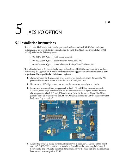
3. Locate the two sets of four jumpers each at both JP3 and JP4 on the motherboard.<br />
Likewise, locate edge connector JP5 on the motherboard. (See figure below). Remove<br />
the jumpers from both JP3 and JP4 and reserve them for future use if you like. (These<br />
jumpers must be re-installed if the AES I/O module is removed and the Hx is converted<br />
back to analog operation).<br />
4. Locate the two gold plated mounting holes shown in the figure. Take one of the board<br />
standoffs (1308-00023-100) and screw the male end into the mounting hole located<br />
between JP3 and JP4. Take the other standoff and screw the male end into the mounting<br />
hole located below capacitor C137.