Hx1-Hx2 Manual-1.4.1 - Telos
Hx1-Hx2 Manual-1.4.1 - Telos
Hx1-Hx2 Manual-1.4.1 - Telos

You also want an ePaper? Increase the reach of your titles
YUMPU automatically turns print PDFs into web optimized ePapers that Google loves.
EXAMPLE<br />
INTERFACE<br />
OPTION<br />
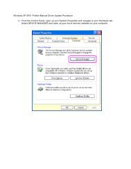
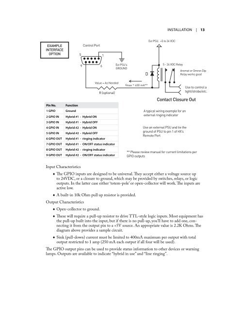
Pin No. Function<br />
1 GPIO Ground<br />
GROUND<br />
2 GPIO IN Hybrid #1 - Hybrid ON<br />
3 GPIO IN Hybrid #1 - Hybrid OFF<br />
4 GPIO IN Hybrid #2 - Hybrid ON<br />
5 GPIO IN Hybrid #2 - Hybrid OFF<br />
6 GPIO OUT Hybrid #1 - ringing indicator<br />
7 GPIO OUT Hybrid #1 - ON/OFF status indicator<br />
8 GPIO OUT Hybrid #2 - ringing indicator<br />
** Please review manual for current limitations per<br />
9 GPIO OUT Hybrid #2 - ON/OFF status indicator<br />
GPIO outputs<br />
Input Characteristics<br />
** Please review manual for current limitations per GPIO ** outputs Please review manual for current limitations per GP<br />
InsTallaTIon | 13<br />
♦ The GPIO inputs are designed to be universal. They accept either a voltage source up<br />
to 24VDC, or a closure to ground, which may be provided by switches, relays, or logic<br />
outputs. In the latter case either ‘totem-pole’ or open-collector will work. The inputs are<br />
active low.<br />
♦ A built-in 10k Ohm pull up resistor is provided.<br />
Output Characteristics<br />
♦ Open-collector to ground.<br />
5<br />
9<br />
C<br />
Control Port<br />
6<br />
1<br />
Value = As Needed<br />
R (optional)<br />
GROUND<br />
Inputs 2-5 Outputs 6-9**<br />
Ext PSU’s<br />
GROUND<br />
imax = 400 mA**<br />
Ext PSU. +5 to 24 VDC<br />
Control Port<br />
5 - 24 VDC Relay 6 Ext PSU’s<br />
GROUND<br />
Aromat or Omron Dip<br />
Relay works good<br />
A typical wiring example for an<br />
external ringing indicator<br />
Use an external PSU and tie the<br />
ground of PSU to pin 1 of HX’s<br />
Remote Port<br />
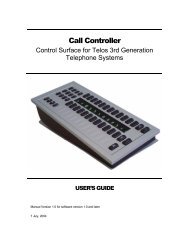
♦ These will require a pull-up resistor to drive TTL-style logic inputs. Most equipment has<br />
the pull-up built into the input, but if there is no pull-up, you’ll have to add one, connecting<br />
it from the output pin to a +5V source. An appropriate value is 2.2K Ohms. The<br />
diagram above provides a sample circuit.<br />
♦ Sink (pull-down) current must be limited to 400mA maximum per output with total<br />
output restricted to 1 amp (250 mA each output if all four will be used).<br />
Value = As Needed<br />
imax = 400 mA**<br />
Use to control a<br />
R (optional) light/strobe/etc.<br />
Contact Closure Out<br />
The GPIO output pins can be used to provide status information to other devices or warning<br />
lamps. Outputs are available to indicate “hybrid in use” and “line ringing”.<br />
5<br />
EXAMPLE<br />
INTERFACE<br />
OPTION<br />
9<br />
D<br />
5<br />
9<br />
GROUND<br />
** Please review manual for current limitations per<br />
GPIO outputs<br />
C<br />
1<br />
5<br />
Inputs 2-5 Outputs 6-9**<br />
9<br />
D<br />
Ext PSU. +5<br />
Use an externa<br />
ground of PSU<br />
Remote Port<br />
5<br />
Con<br />
A typical wiring<br />
external ringin