Hx1-Hx2 Manual-1.4.1 - Telos
Hx1-Hx2 Manual-1.4.1 - Telos
Hx1-Hx2 Manual-1.4.1 - Telos

You also want an ePaper? Increase the reach of your titles
YUMPU automatically turns print PDFs into web optimized ePapers that Google loves.
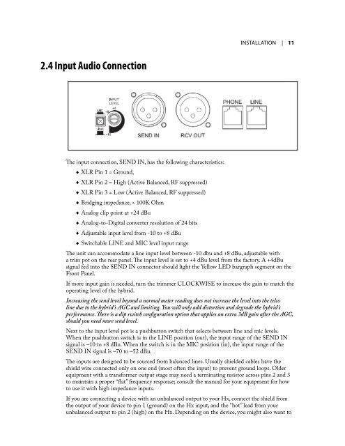
2.4 Input Audio Connection<br />
The input connection, SEND IN, has the following characteristics:<br />
♦ XLR Pin 1 = Ground,<br />
♦ XLR Pin 2 = High (Active Balanced, RF suppressed)<br />
♦ XLR Pin 3 = Low (Active Balanced, RF suppressed)<br />
♦ Bridging impedance, > 100K Ohm<br />
♦ Analog clip point at +24 dBu<br />
♦ Analog-to-Digital converter resolution of 24 bits<br />
♦ Adjustable input level from -10 to +8 dBu<br />
♦ Switchable LINE and MIC level input range<br />
InsTallaTIon | 11<br />
The unit can accommodate a line input level between -10 dbu and +8 dBu, adjustable with<br />
a trim pot on the rear panel. The input level is set to +4 dBu level from the factory. A +4dBu<br />
signal fed into the SEND IN connector should light the Yellow LED bargraph segment on the<br />
Front Panel.<br />
If more input gain is needed, turn the trimmer CLOCKWISE to increase the gain to match the<br />
operating level of the hybrid.<br />
Increasing the send level beyond a normal meter reading does not increase the level into the telco<br />
line due to the hybrid’s AGC and limiting. You will only add distortion and degrade the hybrid’s<br />
performance. There is a dip switch configuration option that applies an extra 3dB gain after the AGC,<br />
should you need more send level.<br />
Next to the input level pot is a pushbutton switch that selects between line and mic levels.<br />
When the pushbutton switch is in the LINE position (out), the input range of the SEND IN<br />
signal is –10 to +8 dBu. When the switch is in the MIC position (in), the input range of the<br />
SEND IN signal is –70 to –52 dBu.<br />
The inputs are designed to be sourced from balanced lines. Usually shielded cables have the<br />
shield wire connected only on one end (most often the input) to prevent ground loops. Older<br />
equipment with a transformer output stage may need a terminating resistor across pins 2 and 3<br />
to maintain a proper “flat” frequency response; consult the manual for your equipment for how<br />
to use it with high impedance inputs.<br />
If you are connecting a device with an unbalanced output to your Hx, connect the shield from<br />
the output of your device to pin 1 (ground) on the Hx input, and the “hot” lead from your<br />
unbalanced output to pin 2 (high) on the Hx. Depending on the device, you might also want to