Service Manual: Stella-C3, S-C3 (B284/B288) Aficio MP161F/Aficio ...
Service Manual: Stella-C3, S-C3 (B284/B288) Aficio MP161F/Aficio ...
Service Manual: Stella-C3, S-C3 (B284/B288) Aficio MP161F/Aficio ...

You also want an ePaper? Increase the reach of your titles
YUMPU automatically turns print PDFs into web optimized ePapers that Google loves.
Model S-<strong>C3</strong> F/SPF MODELS<br />
Machine Code: <strong>B284</strong>/<strong>B288</strong><br />
SERVICE MANUAL<br />
Sep. 29th, 2006<br />
Subject to change
Safety Notice<br />
Important Safety Notices<br />
Prevention of Physical Injury<br />
1. Be sure that the power cord is unplugged before disassembling or assembling parts of the copier or<br />
peripherals.<br />
2. The wall outlet should be near the copier and easily accessible.<br />
3. Note that electrical voltage is supplied to some components of the copier and the paper tray unit even<br />
while the main power switch is off.<br />
4. If any adjustment or operation check has to be made with exterior covers off or open while the main<br />
switch is turned on, keep hands away from electrified or mechanically driven components.<br />
5. If you start a job before the copier completes the warm-up or initializing period, keep hands away<br />
from the mechanical and electrical components until job execution has started. The copier will start<br />
making copies as soon as warm-up or initialization is finished.<br />
6. The inside and the metal parts of the fusing unit become extremely hot while the copier is operating.<br />
Be careful to avoid touching those components with your bare hands.<br />
Health Safety Conditions<br />
Toner and developer are nontoxic, but getting either of these into your eyes may cause temporary eye<br />
discomfort. Try to remove with eye drops or flush with water. If material remains in eye or if discomfort<br />
continues, get medical attention.<br />
Observance of Electrical Safety Standards<br />
The copier and its peripherals must be installed and maintained by a customer service representative who<br />
has completed the training course on those relevant models.<br />
• Keep the machine away from flammable liquids, gases, and aerosols. A fire or an explosion might<br />
occur if this precaution is not observed.<br />
Lithium Batteries<br />
Incorrect replacement of lithium battery(s) on the FCU may pose risk of explosion. Replace only with the<br />
same type or with an equivalent type recommended by the manufacturer. Discard used batteries in<br />
accordance with the manufacturer's instructions.<br />
1
2<br />
Safe and Ecological Disposal<br />
1. Do not incinerate toner bottles or used toner. Toner dust may ignite suddenly if exposed to an open<br />
flame.<br />
2. Dispose of used toner, developer, and organic photoconductors in accordance with local regulations.<br />
(These are nontoxic supplies.)<br />
3. Dispose of replaced parts in accordance with local regulations.<br />
Laser Safety<br />
The Center for Devices and Radiological Health (CDRH) prohibits the repair of laser-based optical units<br />
in the field. The optical housing unit can only be repaired in a factory or at a location with the requisite<br />
equipment. The laser subsystem is replaceable in the field by a qualified Customer Engineer. The laser<br />
chassis is not repairable in the field. Customer engineers are therefore directed to return all chassis and<br />
laser subsystems to the factory or service depot when replacement of the optical subsystem is required.<br />
• Use of controls not specified in this manual, or performance of adjustments or procedures not specified<br />
in this manual, may result in hazardous radiation exposure.<br />
WARNING FOR LASER UNIT<br />
• Turn off the main switch before attempting any of the procedures in the Laser Unit section. Laser<br />
beams can seriously damage your eyes.<br />
CAUTION MARKING:
Symbols and Abbreviations<br />
This manual uses several symbols and abbreviations. The meaning of those symbols and abbreviations is<br />
as follows:<br />
* See or Refer to<br />
Clip ring<br />
E-ring<br />
Screw<br />
Connector<br />
Clamp<br />
SEF Short Edge Feed<br />
LEF Long Edge Feed<br />
Core Technology manual<br />
Cautions, Notes, etc.<br />
The following headings provide special information:<br />
• FAILURE TO OBEY WARNING INFORMATION COULD RESULT IN SERIOUS INJURY OR DEATH.<br />
• Obey these guidelines to ensure safe operation and prevent minor injuries.<br />
• This information provides tips and advice about how to best service the machine.<br />
3
4<br />
TABLE OF CONTENTS<br />
Safety Notice......................................................................................................................................................1<br />
Important Safety Notices..........................................................................................................................1<br />
Laser Safety.....................................................................................................................................................2<br />
Symbols and Abbreviations...............................................................................................................................3<br />
1. Installation<br />
Installation Cautions.........................................................................................................................................11<br />
Installation Requirements.................................................................................................................................12<br />
Environment..................................................................................................................................................12<br />
Machine Level..............................................................................................................................................12<br />
Minimum Operational Space Requirements.............................................................................................13<br />
Power Requirements....................................................................................................................................14<br />
Copier...............................................................................................................................................................15<br />
Accessory Check..........................................................................................................................................15<br />
Installation Procedure..................................................................................................................................15<br />
Optional Hand Set.......................................................................................................................................22<br />
Paper Tray Unit.................................................................................................................................................25<br />
Accessory Check..........................................................................................................................................25<br />
Installation Procedure..................................................................................................................................25<br />
Paper Tray Unit Heater....................................................................................................................................27<br />
Accessory Check..........................................................................................................................................27<br />
Installation Procedure..................................................................................................................................28<br />
Controller Options............................................................................................................................................35<br />
Overview......................................................................................................................................................35<br />
PostScript3 Installation................................................................................................................................36<br />
Wireless LAN (IEEE 802.11b) Installation................................................................................................36<br />
IEEE 1284 Installation.................................................................................................................................38<br />
Bluetooth Installation...................................................................................................................................39<br />
2. Preventive Maintenance<br />
PM Tables.........................................................................................................................................................41<br />
How to Clear the PM Counter.........................................................................................................................43<br />
3. Replacement and Adjustment<br />
Precautions........................................................................................................................................................45<br />
General.........................................................................................................................................................45
Lithium Batteries............................................................................................................................................45<br />
Halogen-free Cable....................................................................................................................................45<br />
Special Tools and Lubricants...........................................................................................................................46<br />
Exterior Covers and Operation Panel............................................................................................................47<br />
Rear Cover...................................................................................................................................................47<br />
Copy Tray.....................................................................................................................................................47<br />
Operation Panel and Upper Covers..........................................................................................................48<br />
Right Door.....................................................................................................................................................49<br />
Bypass Tray..................................................................................................................................................50<br />
Platen Cover Sensor....................................................................................................................................50<br />
Scanner Unit.....................................................................................................................................................51<br />
Exposure Glass............................................................................................................................................51<br />
Lens Block.....................................................................................................................................................51<br />
Exposure Lamp, Lamp Stabilizer Board.....................................................................................................52<br />
Scanner Motor.............................................................................................................................................53<br />
Scanner HP Sensor......................................................................................................................................54<br />
Scanner alignment adjustment....................................................................................................................55<br />
Fusing................................................................................................................................................................57<br />
Fusing Unit....................................................................................................................................................57<br />
Exit Sensor....................................................................................................................................................58<br />
Hot Roller Stripper Pawls.............................................................................................................................58<br />
Hot Roller and Fusing Lamp........................................................................................................................59<br />
Thermoswitches and Thermistor..................................................................................................................61<br />
Pressure Roller..............................................................................................................................................62<br />
Checking the NIP band...............................................................................................................................63<br />
PCU and Quenching Lamp.............................................................................................................................64<br />
PCU...............................................................................................................................................................64<br />
Quenching Lamp..........................................................................................................................................65<br />
Exhaust Fan and Main Motor.........................................................................................................................66<br />
Exhaust Fan..................................................................................................................................................66<br />
Main Motor..................................................................................................................................................67<br />
Paper Feed........................................................................................................................................................68<br />
Paper Feed Roller and Friction Pad............................................................................................................68<br />
5
6<br />
Paper End Sensor.........................................................................................................................................69<br />
Registration Sensor......................................................................................................................................69<br />
Bypass Paper End Sensor...........................................................................................................................70<br />
Bypass Feed Roller......................................................................................................................................71<br />
Bypass Feed Clutch and Friction Pad.........................................................................................................72<br />
Paper Feed and Registration Clutches.......................................................................................................73<br />
Image Transfer..................................................................................................................................................75<br />
Transfer Roller..............................................................................................................................................75<br />
ID Sensor and Duplex Roller.......................................................................................................................76<br />
Discharge plate............................................................................................................................................77<br />
BICU and Controller Board.............................................................................................................................78<br />
BICU..............................................................................................................................................................78<br />
Controller Board..........................................................................................................................................79<br />
Other Replacements.........................................................................................................................................83<br />
Duplex Motor...............................................................................................................................................83<br />
High-Voltage Power Supply Board ...........................................................................................................84<br />
PSU Assembly..............................................................................................................................................85<br />
PSU................................................................................................................................................................85<br />
Contact-Release Solenoid...........................................................................................................................86<br />
Toner Supply Clutch....................................................................................................................................87<br />
FCU...............................................................................................................................................................87<br />
Laser Unit..........................................................................................................................................................89<br />
Location of the Caution Decal....................................................................................................................89<br />
Laser Unit......................................................................................................................................................89<br />
LD Unit and Polygon Mirror Motor............................................................................................................90<br />
ARDF ................................................................................................................................................................91<br />
ARDF.............................................................................................................................................................91<br />
DF Rear Cover..............................................................................................................................................92<br />
Original Feed Unit.......................................................................................................................................92<br />
Separation Roller.........................................................................................................................................93<br />
DF Drive Board............................................................................................................................................93<br />
Original Set and DF Inverter Sensor..........................................................................................................94<br />
DF Registration and DF Exit Sensor............................................................................................................95
DF Feed Motor.............................................................................................................................................96<br />
DF Transport Motor.....................................................................................................................................97<br />
DF Feed Clutch.............................................................................................................................................98<br />
Adjusting Copy Image Area............................................................................................................................99<br />
Printing..........................................................................................................................................................99<br />
Scanning....................................................................................................................................................101<br />
DF Image Adjustment................................................................................................................................104<br />
4. Troubleshooting<br />
<strong>Service</strong> Call Conditions.................................................................................................................................107<br />
Summary....................................................................................................................................................107<br />
Engine SC Code Descriptions..................................................................................................................107<br />
GW SC Code Descriptions......................................................................................................................116<br />
Electrical Component Troubleshooting........................................................................................................129<br />
Sensor/Switch Open Errors.....................................................................................................................129<br />
Blown Fuse Conditions..............................................................................................................................130<br />
BICU LED Display......................................................................................................................................131<br />
5. <strong>Service</strong> Tables<br />
<strong>Service</strong> Program.............................................................................................................................................133<br />
Using SP and SSP Modes.........................................................................................................................133<br />
Copier <strong>Service</strong> Program Mode Tables....................................................................................................134<br />
ID Sensor Error Analysis (SP2-221)........................................................................................................218<br />
Memory Clear...........................................................................................................................................218<br />
Input Check (SP5-803).............................................................................................................................220<br />
Output Check (SP5-804).........................................................................................................................221<br />
Machine No. Setting (SP5-811-001).....................................................................................................223<br />
NVRAM Data Upload/Download..........................................................................................................223<br />
Firmware Update Procedure....................................................................................................................225<br />
Test Pattern Print (SP5-902-001).............................................................................................................230<br />
SMC Print (SP5-990)................................................................................................................................233<br />
Power-on Self Test.....................................................................................................................................233<br />
Printer <strong>Service</strong> Mode.................................................................................................................................234<br />
Scanner Program Mode Table.................................................................................................................234<br />
6. Detailed Section Descriptions<br />
7
8<br />
Overview........................................................................................................................................................237<br />
Component Layout....................................................................................................................................237<br />
Electrical Components..............................................................................................................................239<br />
Paper Path......................................................................................................................................................242<br />
Drive Layout...................................................................................................................................................243<br />
Mainframe.................................................................................................................................................243<br />
ARDF...........................................................................................................................................................244<br />
Block Diagram: PCBs and Components......................................................................................................245<br />
Main PCBs......................................................................................................................................................246<br />
SBU (Sensor Board Unit)..........................................................................................................................246<br />
Copy Process.................................................................................................................................................248<br />
Overview....................................................................................................................................................248<br />
Scanning.........................................................................................................................................................250<br />
Overview....................................................................................................................................................250<br />
Scanner Drive............................................................................................................................................251<br />
Image Processing...........................................................................................................................................252<br />
Overview....................................................................................................................................................252<br />
Image Processing Path..............................................................................................................................253<br />
Original Modes.........................................................................................................................................253<br />
Image Processing Steps for Each Mode..................................................................................................256<br />
Mode Adjustments.....................................................................................................................................257<br />
Laser Exposure...............................................................................................................................................258<br />
Overview....................................................................................................................................................258<br />
LD Safety Switches....................................................................................................................................259<br />
Photoconductor Unit (PCU)...........................................................................................................................260<br />
Overview....................................................................................................................................................260<br />
Drum Drive.................................................................................................................................................261<br />
Drum Charge.................................................................................................................................................262<br />
Overview....................................................................................................................................................262<br />
Charge Roller Voltage Correction...........................................................................................................263<br />
Charge Roller Cleaning............................................................................................................................264<br />
Detection of New PCU..............................................................................................................................264<br />
Development..................................................................................................................................................266
Overview....................................................................................................................................................266<br />
Development Bias......................................................................................................................................267<br />
Toner Supply..............................................................................................................................................267<br />
Toner Density Control................................................................................................................................268<br />
Toner Supply If Sensor Reading is abnormal .........................................................................................269<br />
Detection of Toner Near End and Toner End .........................................................................................270<br />
Drum Cleaning and Toner Recycling...........................................................................................................271<br />
ARDF Operation............................................................................................................................................272<br />
Pick-Up and Separation............................................................................................................................272<br />
Clutch Operation.......................................................................................................................................272<br />
Original Transport and Exit......................................................................................................................272<br />
Paper Feed.....................................................................................................................................................275<br />
Overview....................................................................................................................................................275<br />
Paper Feed Drive Mechanism..................................................................................................................276<br />
Paper Feed and Separation.....................................................................................................................278<br />
Paper Lift Mechanism................................................................................................................................278<br />
Paper End Detection..................................................................................................................................279<br />
Image Transfer and Paper Separation.........................................................................................................281<br />
Overview....................................................................................................................................................281<br />
Image Transfer Current Timing.................................................................................................................281<br />
Transfer Roller Cleaning...........................................................................................................................282<br />
Image Fusing and Paper Exit........................................................................................................................283<br />
Overview....................................................................................................................................................283<br />
Hot Roller Drive.........................................................................................................................................284<br />
Pressure Roller............................................................................................................................................285<br />
Pressure Release........................................................................................................................................285<br />
Separation.................................................................................................................................................286<br />
Fusing Temperature Control.....................................................................................................................286<br />
Duplex Unit.....................................................................................................................................................290<br />
Important Components.............................................................................................................................290<br />
Duplex Printing Process.............................................................................................................................291<br />
Energy Saver Modes.....................................................................................................................................295<br />
Overview....................................................................................................................................................295<br />
9
10<br />
AOF............................................................................................................................................................296<br />
Timers.........................................................................................................................................................296<br />
Recovery....................................................................................................................................................296<br />
GW Controller...............................................................................................................................................297<br />
Overview....................................................................................................................................................297<br />
Controller Functions...................................................................................................................................298<br />
Scanner Functions.....................................................................................................................................300<br />
7. Specifications<br />
General Specifications..................................................................................................................................303<br />
Copier........................................................................................................................................................303<br />
Printer..........................................................................................................................................................305<br />
Scanner......................................................................................................................................................306<br />
ARDF...........................................................................................................................................................307<br />
Paper Tray Unit..........................................................................................................................................308<br />
Supported Paper Sizes..................................................................................................................................309<br />
Original Paper Sizes.................................................................................................................................309<br />
Paper Feed.................................................................................................................................................310<br />
Machine Configuration.................................................................................................................................313<br />
Mainframe (<strong>B284</strong>/<strong>B288</strong>)........................................................................................................................313<br />
System Components..................................................................................................................................314
1. Installation<br />
Installation Cautions<br />
• Before installing an optional unit, do the following:<br />
• Print out all messages stored in the memory, all user-programmed items, and a system parameter<br />
list.<br />
• If there is a printer option on the machine, print out all data in the printer buffer.<br />
• Turn off the main switch and disconnect the power cord, the telephone line, and the network<br />
cable.<br />
1<br />
11
1<br />
12<br />
1. Installation<br />
Installation Requirements<br />
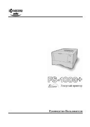
Environment<br />
–Temperature and Humidity Chart–<br />
• Temperature Range: 10°C to 32°C (50°F to 89.6°F)<br />
• Humidity Range: 15% to 80% RH<br />
• Ambient Illumination: Less than 1,500 lux (Do not expose to direct sunlight.)<br />
• Ventilation: Room air should turn over at least 3 times/hr/person<br />
• Ambient Dust: Less than 0.1 mg/m 3<br />
• Do not install the machine where it will be exposed to direct sunlight or to direct airflow (from a fan,<br />
air conditioner, air cleaner, etc.).<br />
• Do not install the machine where it will be exposed to corrosive gas.<br />
• Place the machine on a firm and level base.<br />
• Do not install the machine where it may be subjected to strong vibration.<br />
Machine Level<br />
Front to back: Within 5 mm (0.2") of level
Right to left: Within 5 mm (0.2") of level<br />
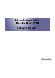
Minimum Operational Space Requirements<br />
Place the machine near the power source, providing clearance as shown.<br />
A: Front – 750 mm (29.6")<br />
B: Left – 100 mm (3.9")<br />
C: Rear – 105 mm (4.1")<br />
D: Right – 230 mm (9.0")<br />
E: Depth – 450 mm (17.7")<br />
F: Width – 485 mm (19.1")<br />
Installation Requirements<br />
• The 750-mm front space indicated above is sufficient to allow the paper tray to be pulled out.<br />
Additional space is required to allow an operator to stand at the front of the machine.<br />
1<br />
13
1<br />
14<br />
1. Installation<br />
• Actual minimum space requirement for left, rear, and right sides is 10mm (0.4") each, but note that<br />
this will not allow room for opening of the bypass tray, right door, platen cover, or ARDF unit.<br />
Power Requirements<br />
• Make sure that the wall outlet is near the machine and easily accessible. After completing installation,<br />
make sure the plug fits firmly into the outlet.<br />
• Avoid multiple connections to the same power outlet.<br />
• Be sure to ground the machine.<br />
Input voltage:<br />
North America: 110 – 120 V, 60 Hz, 8 A<br />
Europe: 220 – 240 V, 50/60 Hz, 4 A<br />
Image quality guaranteed at rated voltage ± 10%.<br />
Operation guaranteed at rated voltage ± 15%.
Copier<br />
Accessory Check<br />
Fax Model (<strong>B284</strong>)/ Printer/Scanner and Fax Model (<strong>B288</strong>)<br />
Description Q’ty<br />
NECR (-17) 1<br />
EU Safety Sheet (-67, -26) 1<br />
Paper Size Decal 1<br />
Model Name Plate - RIC,LAN, GES,INF (-29) 1 set<br />
Handset Bracket (-17) 1<br />
Screw for Handset Bracket (-17) 2<br />
Modular Cable (-17) 1<br />
Connecter Cover for TEL (-17) 1<br />
User Function Key Decal (-17, -29 1<br />
Ferrite Core for TEL Line 1<br />
Operating Instructions - Book (-17, -29) 1 set<br />
Operating Instructions – CD ROM (-17, -29) 1 set<br />
Installation Procedure<br />
• Make sure that the copier remains unplugged during installation.<br />
Copier<br />
1<br />
15
1<br />
16<br />
1. Installation<br />
1. Remove the all strips of tape.<br />
2. Remove the bag [A], SMC and A3 sheet of paper on the exposure glass.<br />
3. Remove the spacing wedge [B].
4. Remove the three scanner lock pins. (A tag is hanging from each pin.) To remove: Grasp the base of<br />
the pin [C], turn the pin 90 degrees, and pull it down and out.<br />
5. Remove the tags from the pins.<br />
6. Break each pin off the base [C].<br />
7. Discard the pin part [D].<br />
8. Set each base [C] back into its original hole, turning it 90° to lock it into place. (Be sure to do this for<br />
all three pins.)<br />
9. Open the front door [E].<br />
10. Lift lever [F], press in on latch [G] and pull the bottle holder [H] out. (You do not need to pull it completely<br />
out of the machine.)<br />
11. Take a new bottle of toner, and shake it several times.<br />
Copier<br />
1<br />
17
1<br />
18<br />
1. Installation<br />
12. Remove the outer cap [I].<br />
• Do not remove the inner cap [J].<br />
13. Load the bottle on the holder.<br />
• Do not forcefully turn the toner bottle on the holder. After you turn on the main power switch, the<br />
copier sets the bottle in place.<br />
14. Push the bottle holder back into the machine.<br />
15. Press the latch [K] down to lock the holder.
16. Remove the padding [L].<br />
17. Pull each tabbed strip [M] out of the PCU with one hand, supporting the PCU with the other.<br />
• Do not pull both strips at the same time, as this could damage the PCU.<br />
18. Close the front door.<br />
19. Pull out the paper tray, and remove the tape securing the end fence in the compartment.<br />
20. Push the bottom plate down, and then load the paper.<br />
21. Adjust the side fences. If you load paper shorter than A4, set the end fence in the correct position.<br />
22. Push the tray back into the copier.<br />
23. Attach the appropriate Brand Decal to the center [N] of the front door if necessary.<br />
24. Attach the appropriate tray number decal and paper-size decal to the paper tray [O].<br />
Copier<br />
1<br />
19
1<br />
20<br />
1. Installation<br />
25. Install optional units (if any).<br />
26. Attach the ferrite core [P] to the network cable when connecting the cable.<br />
27. Attach the ferrite core to the telephone line as same manner step 26.<br />
28. Connect the telephone line to the "LINE" jack.<br />
• The end of the ferrite core must be about 10 cm (4") from the end [Q] of the cable.<br />
29. Plug in the machine and turn on the main power switch.<br />
30. Select the language used in the operation panel as necessary ( > Language).<br />
Interface settings<br />
For <strong>B284</strong><br />
1. Start the SP mode.<br />
2. Select SP5-985-001 (NIC setting) and change the setting value to "0" (OFF).<br />
3. Select SP5-985-002 (USB setting) and change the setting value to "0" (OFF).<br />
4. Turn the main switch off and on.<br />
For <strong>B288</strong><br />
1. Start the SP mode.<br />
2. Select SP5-985-001 (NIC setting) and change the setting value to "1" (ON).<br />
3. Select SP5-985-002 (USB setting) and change the setting value to "1" (ON).<br />
4. Turn the main switch off and on.
Copier settings<br />
1. Start the SP mode.<br />
2. Select SP5-801-001 and execute the initialization.<br />
3. Exit the SP mode, and then start the UP mode.<br />
4. Select the "@Remote <strong>Service</strong>" ("User Tool" > "System Settings > Administrator Tools" > "Extended<br />
Security" > @Remote <strong>Service</strong>") and select "Prohibit".<br />
5. Exit the UP mode, and then start the SP mode.<br />
6. Select SP5-870-003 and execute initialization for @Remote.<br />
7. Select SP5-907-001 and specify the "Plug & Play".<br />
8. Select SP5-870-001 and execute writing certification for @Remote S.<br />
9. Select SP5-302-002 and specify the time zone.<br />
10. Select SP5-307-001, 003, and 004 and specify the daylight-saving-time settings.<br />
11. Exit the SP mode and turn the main switch off and on.<br />
12. Start the UP mode.<br />
13. Specify the date and time with "Set Date" or "Set Time" (User Tool" > "System Settings" > "Set Date"<br />
or "Set Time").<br />
14. Turn the main switch off and on.<br />
15. Check the operations.<br />
16. Make a full size copy, and check if the side-to-side and leading edge registrations are correct. If they<br />
are not, adjust the registrations.<br />
Fax Settings<br />
Initializing the Fax unit<br />
When you press the Fax key for the first time after installation, the error "SRAM problem occurred / SRAM<br />
was formatted" will show on the LCD for initializing the program of the fax unit. Turn the main power switch<br />
off/on to clear the error display.<br />
• If another error occurs after initialization, this can be a functional problem.<br />
1. Select fax SP1-101-016 and specify the country code.<br />
2. Select fax SP3-101-001 and specify the service station.<br />
Copier<br />
1<br />
21
1<br />
22<br />
1. Installation<br />
Optional Hand Set<br />
Accessory Check<br />
Check that you have the components and accessories.<br />
No. Description Q’ty<br />
1 Handset 1<br />
2 Handset cradle 1<br />
3 Screws 2<br />
4 Handset manual 1<br />
• The handset bracket is not included in the optional handset kit. The bracket is provided as an accessory<br />
of the copier.
Installation Procedure<br />
1. Attach the handset bracket [A] ( x 2).<br />
• The bracket is an accessory of the copier.<br />
2. Remove the label [B] from the handset cradle [C].<br />
3. Attach the cradle to the bracket ( x 2).<br />
4. Reattach the label.<br />
5. Set the handset [D] on the cradle.<br />
Copier<br />
1<br />
23
1<br />
24<br />
1. Installation<br />
6. Connect the cable [E] to the TEL jack at the left side of the copier.
Paper Tray Unit<br />
Accessory Check<br />
Confirm that you have these accessories.<br />
Description Q’ty<br />
1. Paper-size decals 1 sheet<br />
2. Installation Procedure (for service person) 1<br />
3. Installation Procedure (for user) 1<br />
Installation Procedure<br />
• Unplug the main machine's power cord before starting the following procedure.<br />
1. Remove the tape at [A], and the tape and cardboard at [B].<br />
Paper Tray Unit<br />
2. Pull the paper tray part way out of the unit, remove the tape and cardboard at [C], and push the tray<br />
back in.<br />
1<br />
25
1<br />
26<br />
1. Installation<br />
3. Set the machine on the paper tray unit.<br />
4. Remove the paper tray from the paper tray unit.<br />
5. Load paper into the paper tray. Adjust the side and end fences as necessary. If loading 8 1 / 2"x 14"<br />
paper, remove the end fence and set it into the special compartment.<br />
6. Set the paper tray back into the paper tray unit.<br />
7. Stick on the appropriate tray-number decal and paper-size decal, at the locations indicated in the<br />
illustration.
Paper Tray Unit Heater<br />
Accessory Check<br />
Confirm that you have the accessories listed below.<br />
Description Q’ty<br />
1. Grounding wire 1<br />
2. Relay harness 1<br />
3. Clamps 2<br />
4. Ferrite core 1<br />
5. Heater fastening screws 2<br />
6. PTU fastening screws 3<br />
7. Grounding screw 1<br />
8. Decal for copier 1<br />
9. Decal for paper unit 1<br />
10. Tie wrap 1<br />
Paper Tray Unit Heater<br />
1<br />
27
1<br />
28<br />
1. Installation<br />
Installation Procedure<br />
• Unplug the main machine's power cord before starting the following procedure.<br />
1. Remove the paper tray unit from the copier if it is already installed.<br />
2. Remove the paper trays from the copier and from the paper tray unit.
3. Remove the ground screw [1] at the rear of the paper tray unit.<br />
4. Fasten the heater [2] and the supplied ground wire [3] to the paper tray unit ( x 3). Note that [1] is<br />
the ground screw you removed in the previous step and [4] and [5] are the two supplied heater<br />
fastening screws.<br />
• Be sure to position the ground wire [3] and heater harness [6] so that they are out of the way of<br />
the copier when you set it onto the paper tray unit.<br />
5. Set the copier onto the paper tray unit.<br />
6. Screw the paper tray unit into place using three supplied PTU fastening screws.<br />
Paper Tray Unit Heater<br />
1<br />
29
1<br />
30<br />
1. Installation<br />
7. Open the front door and remove the copy tray [7] (×1).<br />
8. Close the front door.<br />
9. Remove the memory card cover [8] ( x 1).<br />
10. Remove the rear cover [9] ( x 5).
11. Remove the upper left cover [10].<br />
12. Remove the controller box [11] ( x 1, x 5).<br />
13. Remove the support bracket [12] ( x 3).<br />
Paper Tray Unit Heater<br />
1<br />
31
1<br />
32<br />
1. Installation<br />
14. Pass the heater harness through the hole [15] at the rear of the copier.<br />
15. Pass relay harness [16] through the opening [17] (at the rear of the PSU) and through the other<br />
opening [15].<br />
16. Connect the relay harness to the heater's harness [18].<br />
17. Pull the relay harness back into the copier.<br />
18. Attach the ferrite core [19] over the relay harness.
19. Push the ferrite core back so that it is over the heater's harness.<br />
20. Wrap the heater's harness once around the ferrite core [20].<br />
21. Locate the ferrite core at the rear [24] of the copier behind the rear clamps.<br />
22. Secure the ferrite core with the supplied tie wrap [21].<br />
23. Clip off the excess length of the tie wrap.<br />
24. Connect the relay harness connector [22] to the large connector at the front center of the PSU.<br />
25. Screw the ground wire [23] to the PSU bracket with the included grounding screw.<br />
26. Attach the clamps [24] to the PSU bracket.<br />
27. Attach the heater harness though the clamps.<br />
28. Position the harness so that the front clamp is between the two bindings [25] on the harness.<br />
29. Fasten the clamps.<br />
30. Pull the excess length of the heater's harness out the opening at the rear.<br />
• Be sure that the harness passes on the side of the grounding plate at the bottom of the opening.<br />
(The front of the grounding plate must remain clear.)<br />
31. Arrange the excess harness length so that it sits beneath the FCU cover plate.<br />
32. Attach the caution decals to the locations shown in the illustration.<br />
Paper Tray Unit Heater<br />
1<br />
33
1<br />
34<br />
1. Installation<br />
33. Reassemble the copier.<br />
34. Plug in the power cord, and check the operation.
Controller Options<br />
Overview<br />
This machine has I/F card slots and SD card slots for optional I/F connections and applications.<br />
I/F Card Slot<br />
• Slot [A] is used for one of the optional I/F connections: (IEEE1284, IEEE802.11 (Wireless LAN) or<br />
Bluetooth).<br />
SD Card Slot<br />
• Slot [1] is used for the printer/scanner application only.<br />
• Slot [2] is used for PostScript3.<br />
• Slot [3] is used for the service use.<br />
Controller Options<br />
1<br />
35
1<br />
36<br />
1. Installation<br />
PostScript3 Installation<br />
• Unplug the machine power cord before starting the following procedure.<br />
Installation Procedure<br />
1. Install the PostScript3 SD card into the slot 2 [A].<br />
2. Turn on the main power switch.<br />
3. Print out the configuration page (User Tools/ Counter > Printer Features > List/ Test Print), and then<br />
check that this device is detected.<br />
4. Attach the "Adobe PostScript3" decal to the front cover of the machine.<br />
Wireless LAN (IEEE 802.11b) Installation<br />
• Unplug the machine power cord before starting the following procedure.
Component Check<br />
No. Description Q’ty<br />
1 Wireless Adapter 1<br />
2 Wireless LAN Card 1<br />
3 LAN Card Cover 4<br />
4 Caution Sheet 1<br />
5 Label 1<br />
Installation Procedure<br />
1. Remove the interface cover [A] ( x 2).<br />
2. Install the Wireless adaptor into the slot A [B] ( x 2).<br />
3. Install the Wireless LAN card in the wireless adaptor.<br />
4. Attach the antenna cap to the wireless LAN card.<br />
5. Turn on the main power switch.<br />
Controller Options<br />
1<br />
37
1<br />
38<br />
1. Installation<br />
6. Print out the configuration page (User Tools/Counter > Printer Features > List/Test Print), and then<br />
check that this device is detected.<br />
If reception is poor, you may need to move the machine:<br />
• Make sure that the machine is not located near an appliance or any type of equipment that could<br />
generate a strong magnetic field.<br />
• Position the machine as close as possible to the access point.<br />
SP Mode Settings for IEEE 802.11b Wireless LAN<br />
The following SP commands can be set for IEEE 802.11b<br />
SP No. Name Function<br />
5840 004 SSID Used to confirm the current SSID setting.<br />
5840 006 Channel MAX Sets the maximum range of the channel settings for the country.<br />
5840 007 Channel MIN<br />
Sets the minimum range of the channel settings allowed for your<br />
country.<br />
5840 011 WEP Key Select Used to select the WEP key (Default: 00).<br />
5840 018 SSID Check Used to check the SSID.<br />
5840 020 WEP Mode<br />
IEEE 1284 Installation<br />
Used to display the maximum length of the string that can be<br />
used for the WEP Key entry.<br />
• Unplug the machine power cord before starting the following procedure.<br />
Component Check<br />
No. Description Q’ty<br />
1 IEEE1284 Interface Ass’y 1<br />
2 UL Sheet 1<br />
3 Caution Sheet 1
Installation Procedure<br />
1. Remove the interface cover [A] ( x 2).<br />
2. Install the IEEE 1284 board into interface slot A [B] ( x 2).<br />
3. Turn on the main power switch.<br />
4. Print out the configuration page (User Tools/Counter > Printer Features > List/Test Print), and then<br />
check that this device is detected.<br />
Bluetooth Installation<br />
• Unplug the machine power cord before starting the following procedure.<br />
Component Check<br />
No. Description Q’ty<br />
1 Wireless Adapter 1<br />
2 Bluetooth Card 1<br />
Controller Options<br />
1<br />
39
1<br />
40<br />
1. Installation<br />
3 Bluetooth Card Adapter 1<br />
4 Bluetooth Card Cover 1<br />
5 UL/FCC Sheet 1<br />
6 Caution Sheet 1<br />
Installation Procedure<br />
1. Remove the interface cover [A] ( x 2).<br />
2. Install the Wireless adaptor into interface slot A [B] ( x 2).<br />
3. Install the Bluetooth card in the wireless adaptor.<br />
4. Attach the antenna cap to the Bluetooth card.<br />
5. Turn on the main power switch.<br />
6. Print out the configuration page (User Tools/ Counter > Printer Features > List/ Test Print), and then<br />
check that this device is detected.
2. Preventive Maintenance<br />
PM Tables<br />
Reset the PM counter (SP7-804-001) after doing maintenance work.<br />
Key: AN: As necessary, C: Clean, R: Replace, I: Inspect<br />
OPTICS<br />
Every 45k Every 90k AN NOTE<br />
Reflector C C Optics cloth<br />
1st mirror C C Optics cloth<br />
2nd mirror C C Optics cloth<br />
3rd mirror C C Optics cloth<br />
Platen cover C C Dry cloth<br />
Exposure glass C C Dry cloth<br />
Toner shield glass C C Dry cloth<br />
DRUM AREA<br />
PCU R Clean toner-bottle holder.<br />
Transfer roller R<br />
Discharge plate R<br />
PAPER FEED<br />
Paper feed roller R C Water or alcohol.<br />
Friction pad R C Dry cloth<br />
Bottom-plate pad C C Water or alcohol.<br />
Registration roller C C Water or alcohol.<br />
FUSING UNIT<br />
Hot roller R<br />
Pressure roller R<br />
2<br />
41
2<br />
42<br />
2. Preventive Maintenance<br />
Hot roller bearings R<br />
Pressure-roller<br />
bushings<br />
Inlet guide C<br />
Outlet guide C<br />
Hot roller stripper<br />
pawls<br />
Thermistor C<br />
ARDF<br />
Every 45k Every 90k AN NOTE<br />
I<br />
R<br />
Every 90k AN NOTE<br />
Separation roller R C Water or alcohol<br />
Pick-up roller R C Water or alcohol<br />
Feed roller R C Water or alcohol<br />
White plate C Water or alcohol<br />
DF exposure glass C Water<br />
Rollers R0, R1, R2 C Water or alcohol<br />
Registration sensor<br />
reflector<br />
PAPER TRAY UNIT<br />
Paper feed roller R<br />
C Water or alcohol<br />
Every 120k AN NOTE<br />
Bottom-plate pad C Dry cloth<br />
Friction pad R
How to Clear the PM Counter<br />
Reset the PM counter after your maintenance work.<br />
1. Activate the SP mode.<br />
2. Select SP7-804-001.<br />
3. Press the EXECUTE key [A]. The message "Completed" is displayed when the program ends normally.<br />
An error message is displayed if the program ends abnormally.<br />
4. Press the (Escape) key [B] to end the program.<br />
How to Clear the PM Counter<br />
2<br />
43
2<br />
44<br />
2. Preventive Maintenance
3. Replacement and Adjustment<br />
Precautions<br />
General<br />
• Turn off the main power switch and unplug the machine before starting replacement.<br />
Before turning off the main power switch, check that no mechanical component is operating. Mechanical<br />
components may stop out of their home positions if you turn off the main power switch while they are<br />
operating. The component may be damaged if you try to remove it when it is not in the home position.<br />
Lithium Batteries<br />
• Incorrect replacement of lithium battery(s) on the controller or on the fax unit poses risk of explosion.<br />
Replace only with the same type or with an equivalent type recommended by the manufacturer.<br />
Discard used batteries in accordance with the manufacturer’s instructions.<br />
Halogen-free Cable<br />
• Use extreme caution while handling cables.<br />
To comply with local regulations, halogen-free cables are used in this machine. Halogen-free cables are<br />
environment-friendly, but no stronger than conventional cables. These cables may be damaged in any of<br />
the following cases:<br />
• The cable is caught between hard objects such as brackets, screws, PCBs, and exterior covers.<br />
• The cable is rubbed on a hard object such as brackets, screws, PCBs, and exterior covers.<br />
• The cable is scratched with a hard object such as brackets, screws, PCBs, exterior covers,<br />
screwdrivers, and fingernails.<br />
3<br />
45
3<br />
46<br />
3. Replacement and Adjustment<br />
Special Tools and Lubricants<br />
Part Number Description Q’ty<br />
A1849501 Optics Adjustment Tools (2 pcs/set) 1 set<br />
A2929500 Test Chart – S5S (10 pcs/set) 1 set<br />
VSSM9000 Digital Multimeter – Fluke 87 1<br />
N8036701 Flash Memory Card (4MB) 1<br />
N8031000 Case for Flash Memory Card 1<br />
A2579300 Grease Barrierta – S552R 1<br />
52039502 Silicon Grease 501 1
Exterior Covers and Operation Panel<br />
Rear Cover<br />
1. Open the right door [A].<br />
2. Rear cover [B] ( x 5)<br />
Copy Tray<br />
Exterior Covers and Operation Panel<br />
• Make sure that the cables under the copy tray are in place before reassembling the copier. If these<br />
cables are caught between the copy tray and the inner cover, they may be severely damaged.<br />
3<br />
47
3<br />
48<br />
3. Replacement and Adjustment<br />
1. Open the front door [A].<br />
2. Copy tray [B] ( x 1)<br />
Reassembling<br />
There are several cables under the front end of the copy tray. To set these cables in place, gently pull these<br />
cables to the left-hand side (toward the PSU) and hold them there as you attach the copy tray.<br />
Operation Panel and Upper Covers<br />
1. Remove the ARDF.
2. Rear cover (* "Rear Cover")<br />
3. Slide the upper left cover [A] to the rear.<br />
4. Rear scale [B] ( x 3)<br />
5. Slide the upper right cover [C] to the rear.<br />
6. Front left cover [D] ( x 2)<br />
7. Operation panel [E] (x 4, x 1)<br />
8. Front right cover [F]<br />
Right Door<br />
1. Open the right door [A].<br />
2. Release the strap [B].<br />
3. Right door ( × 1)<br />
Exterior Covers and Operation Panel<br />
3<br />
49
3<br />
50<br />
3. Replacement and Adjustment<br />
Bypass Tray<br />
1. Press the stopper rails [A] inward.<br />
Platen Cover Sensor<br />
1. Rear cover (* "Rear Cover")<br />
2. Rear scale (* "Operation Panel and Upper Covers")<br />
3. Platen cover sensor [A] (× 1, hook)
Scanner Unit<br />
To clean the mirrors and lenses, use a blower brush or wet cotton.<br />
Exposure Glass<br />
To clean the exposure glass, use alcohol or glass cleaner.<br />
1. Rear cover (* "Rear Cover")<br />
2. Rear scale, upper right cover (* "Operation Panel and Upper Covers")<br />
3. Exposure glass [A]<br />
Reassembling<br />
Make sure that the marking on the glass is at the rear left corner, and that the left edge of the glass is aligned<br />
flush against the support ridge [B] on the frame.<br />
Adjustment<br />
When replacing the white plate, perform the "Scan Auto Adjustment" (*SP4-428-001).<br />
Lens Block<br />
• Do not disassemble the lens block. The lens block is precision adjusted before shipment.<br />
• Do not touch the screws on the CCD. The CCD is precision adjusted before shipment.<br />
Scanner Unit<br />
3<br />
51
3<br />
52<br />
3. Replacement and Adjustment<br />
1. Exposure glass (* "Exposure Glass")<br />
2. Front left cover, operation panel (* "Operation Panel and Upper Covers")<br />
3. Release the cable from the four clamps [A].<br />
4. Lens block [B] ( × 4, 1 flat cable)<br />
• Do not loosen the paint-locked screws holding the lens unit in place.<br />
• After installing a new lens block, carry out copy adjustments (* "Adjusting Copy Image Area").<br />
Exposure Lamp, Lamp Stabilizer Board<br />
Do not fold the exposure cable on the exposure lamp.
1. Exposure glass (* "Exposure Glass")<br />
2. Front left cover, operation panel (* "Operation Panel and Upper Covers")<br />
3. Slide the first scanner to a position where the lamp and scanner are clear of the metal lids.<br />
4. Disconnect the lamp connector [A].<br />
5. Remove either or both of the following:<br />
• Exposure lamp [B] ( x 1)<br />
• Lamp stabilizer board [C] ( x 2, 1 flat cable)<br />
Scanner Motor<br />
1. Rear cover (* "Rear Cover")<br />
2. Rear scale, upper right cover (* "Operation Panel and Upper Covers")<br />
3. Remove the right platen stay holder [A] ( x 3).<br />
Scanner Unit<br />
3<br />
53
3<br />
54<br />
3. Replacement and Adjustment<br />
4. Scanner motor [B] ( × 3, 1 spring, 3 screw holders, × 1)<br />
Reinstalling<br />
When reinstalling, fasten the screws loosely, set the spring in place, and tighten up the screws.<br />
Scanner HP Sensor<br />
1. Rear cover (* "Rear Cover")<br />
2. Front left cover (* "Operation Panel and Upper Covers")<br />
3. Scale plate (* "Scale Plate")
4. Scanner HP sensor [A] ( × 1, hook)<br />
• Move the first scanner from the home position if you have difficulty removing the sensor.<br />
Scanner alignment adjustment<br />
1. Rear cover (* "Rear Cover")<br />
2. Rear scale, upper right cover, front left cover, operation panel (* "Operation Panel and Upper<br />
Covers")<br />
3. Exposure glass (* ”Exposure Glass").<br />
4. Loosen the 2 screws holding the 1st and 2nd scanner belts in place.<br />
5. Slide the 1st and 2nd scanners so that all four of the following are roughly aligned on both the front<br />
and back sides:<br />
• The hole on the copier's lid<br />
• The hole on the 1st scanner<br />
• The corner right hole on the 2nd scanner<br />
• The hole at the base of the scanner<br />
Scanner Unit<br />
3<br />
55
3<br />
56<br />
3. Replacement and Adjustment<br />
6. Insert the two optics adjustment tools [A], and adjust the scanners as necessary so that the tools go<br />
through all four holes.<br />
7. Tighten the two screws that you loosened at step 2 above, so that the belts are firmly clamped into<br />
place.<br />
8. Remove the adjustment tools.
Fusing<br />
Fusing Unit<br />
• Before handling the fusing unit, make sure that the unit is cool enough. The fusing unit can be very hot.<br />
1. Copy tray (* "Copy Tray")<br />
2. Open the right door.<br />
3. Connector cover [A] ( x 1)<br />
• When reinstalling, attach the ground wire.<br />
4. Fusing unit [B] ( x 2, x 4)<br />
Fusing<br />
3<br />
57
3<br />
58<br />
3. Replacement and Adjustment<br />
Exit Sensor<br />
1. Fusing unit (* "Fusing Unit")<br />
2. Exit sensor [A] ( × 1)<br />
Hot Roller Stripper Pawls<br />
• Take care not to damage the hot roller stripper pawls and the tension springs.
1. Fusing unit (* "Fusing Unit")<br />
2. Separate the fusing unit into two sections: the hot roller section [A] and the pressure roller section [B]<br />
( x 2).<br />
After removing the screws, lower the pressure roller section about halfway and then slide it toward<br />
the front side to detach it.<br />
3. Support rollers [C]<br />
4. Hot roller stripper pawls [D]<br />
• Remove the spacer [E] ( x 1) if you are removing the hot roller assembly (* "Hot Roller &<br />
Fusing Lamp").<br />
Hot Roller and Fusing Lamp<br />
• Do not touch the fusing lamp and rollers with your bare hands.<br />
Fusing<br />
3<br />
59
3<br />
60<br />
3. Replacement and Adjustment<br />
1. Hot roller stripper pawls and spacers (* " Hot Roller Stripper Pawls")<br />
2. Hot roller assembly [A] ( x 2)<br />
3. Fusing lamp [B]<br />
• When reassembling, check that the direction of the fusing lamp is correct.<br />
4. Hot roller [C] (2 C-rings, 1 spacer, 1 gear, 2 bushings, 1 cover [D])<br />
Reassembling<br />
Be sure that:<br />
• The fusing lamp is positioned correctly.<br />
• The fusing lamp does not touch the internal part of the hot roller.
Thermoswitches and Thermistor<br />
1. Hot roller assembly (* "Hot Roller & Fusing Lamp")<br />
2. Thermoswitches ( x 2 for each)<br />
3. Thermistor ( x 1)<br />
Reassembling<br />
Make sure of the following:<br />
• That the thermistor is in contact with the hot roller.<br />
• That the hot roller turns smoothly.<br />
• Do not recycle a thermoswitch that is already opened. Safety is not guaranteed if you do this.<br />
Fusing<br />
3<br />
61
3<br />
62<br />
3. Replacement and Adjustment<br />
Pressure Roller<br />
1. Separate the fusing unit into two sections (* "Hot Roller Stripper Pawls").<br />
2. Fusing entrance guide [A]<br />
3. Two springs [B][C]<br />
4. Two pressure arms [D][E]<br />
5. Bushing [F]<br />
6. Pressure roller [G]
Checking the NIP band<br />
You can check the nip band to see if the fusing unit is in a good condition–especially, if the hot roller and<br />
pressure roller are correctly installed.<br />
1. Activate the SP mode.<br />
2. Select SP1-109-001.<br />
3. Specify "1."<br />
4. Press the OK key.<br />
5. Press the key. The copy mode is activated.<br />
6. Place an OHP sheet on the by-pass tray.<br />
7. Press the key. The copier feeds the OHP sheet, and stops it between the hot roller and the pressure<br />
roller for about 20 seconds.<br />
8. Wait until the OHP sheet is output.<br />
9. Press the key.<br />
10. Make sure SP1-109-001 is selected.<br />
11. Specify "0".<br />
12. Press the OK key.<br />
13. Quit the SP mode.<br />
You see an opaque stripe on the OHP sheet. This is the trace of the nip band. The normal nip band is<br />
symmetrical on the OHP sheet. Both ends are slightly thicker than the center.<br />
• There are no specifications or standards for the nip band of this copier.<br />
Fusing<br />
3<br />
63
3<br />
64<br />
3. Replacement and Adjustment<br />
PCU and Quenching Lamp<br />
When handling the photo conductor unit (PCU), use caution:<br />
• Do not touch the OPC drum with your bare hands. When the OPC drum is unclean, clean it with dry<br />
cloth, or clean it with wet cotton and wipe it with dry cloth.<br />
• Do not use alcohol any other chemicals to clean the OPC drum. These substances damage the OPCdrum<br />
surface.<br />
• Keep PCUs in a cool, dry place.<br />
• Do not expose the OPC to any corrosive gas such as ammonia.<br />
• Do not shake a used PCU. Remaining toner and developer may spill out.<br />
• Dispose of used PCUs in accordance with local regulations.<br />
PCU<br />
1. Open the right door.<br />
• The PCU may become stuck if you try to remove it while the front door is closed.<br />
2. Open the front door.<br />
3. Remove the toner bottle holder.<br />
• Clean all spilled toner off the toner bottle area and the inside of the front door.<br />
4. Pull out the PCU [A] ( x 1).
5. When having installed a new PCU, remove the Styrofoam and tags (* "Installation Procedure" in the<br />
chapter "Installation").<br />
Initialization<br />
After you turn on the main power switch, the copier automatically initializes the new PCU. When the copier<br />
is executing initialization, it is important that you:<br />
• Do not turn off the main power switch.<br />
• Do not open or remove exterior covers.<br />
Quenching Lamp<br />
1. PCU (* "PCU")<br />
2. Quenching lamp [A] ( x 1)<br />
PCU and Quenching Lamp<br />
3<br />
65
3<br />
66<br />
3. Replacement and Adjustment<br />
Exhaust Fan and Main Motor<br />
Exhaust Fan<br />
1. Rear cover (* "Rear Cover")<br />
2. Exhaust fan [A] ( x 2, x 1)<br />
Reassembling<br />
Make sure that the arrow [B] on the frame points to the rear side. The arrow indicates the direction of<br />
airflow.
Main Motor<br />
1. Rear cover (* "Rear Cover")<br />
2. High-voltage power supply board (* "High-Voltage Power Supply Board")<br />
3. Ground plate [A] ( x 1)<br />
4. Main motor with the gear cover [B] ( x 1, x 7, x 2, 2 bushings)<br />
5. All gears [C]<br />
6. Main motor [D] ( x 4)<br />
Reassembling<br />
Attach the main motor before attaching the gears.<br />
Exhaust Fan and Main Motor<br />
3<br />
67
3<br />
68<br />
3. Replacement and Adjustment<br />
Paper Feed<br />
Paper Feed Roller and Friction Pad<br />
When handling the paper tray or the paper feed roller, use caution:<br />
• Do not touch the surface of paper feed rollers.<br />
• To avoid paper jams, correctly set the side and end fences in the paper tray.<br />
1. Paper tray<br />
2. Shaft [A] ( x 1)<br />
3. Remove either or both of the following:<br />
• Paper feed roller [B]<br />
• Friction pad [C]
Paper End Sensor<br />
1. Paper tray<br />
2. Open the right door.<br />
3. PCU (* ”PCU")<br />
4. Paper end sensor [A] ( x 1)<br />
Registration Sensor<br />
1. Paper tray<br />
2. Open the right door.<br />
3. Open the paper guide [A].<br />
• Remove the paper guide (Clip x 1) if you have difficulty removing the registration sensor.<br />
Paper Feed<br />
3<br />
69
3<br />
70<br />
3. Replacement and Adjustment<br />
4. Registration sensor feeler [B]<br />
5. Registration sensor [C] ( x 1)<br />
• Disconnect the connector (CN127 [D]) if you have difficulty removing the registration sensor.<br />
Bypass Paper End Sensor<br />
1. Right door (* "Right Door")<br />
2. Sensor compartment [A]<br />
3. Bypass paper end sensor [B] ( x 1)
Bypass Feed Roller<br />
1. Right door (* "Right Door")<br />
2. Turn the feed roller housing upside down [A] ( x 2).<br />
3. Feed roller shaft [B] (2 snap pawls [C], 1 spacer [D])<br />
4. Bypass feed roller [E]<br />
Paper Feed<br />
3<br />
71
3<br />
72<br />
3. Replacement and Adjustment<br />
Bypass Feed Clutch and Friction Pad<br />
1. Rear cover (* "Rear Cover")<br />
2. Right door (* "Right Door")<br />
3. Disconnect the bypass feed clutch connector [A] (CN93).<br />
4. Bypass feed roller housing [B] ( x 2)<br />
5. Bypass feed clutch [C] ( x 1)<br />
6. Bypass friction pad [D]
Paper Feed and Registration Clutches<br />
1. Paper tray<br />
2. High-voltage power supply board (* "High-Voltage Power Supply Board")<br />
3. Ground plate [A] ( x 1)<br />
4. Gear cover [B] ( x 1, x 7, x 2, 2 bushings)<br />
• Do not remove the main motor from the gear cover.<br />
Paper Feed<br />
3<br />
73
3<br />
74<br />
3. Replacement and Adjustment<br />
5. Ground plate [C] ( x 1)<br />
6. Slowly push the clutch holder [D] and remove the registration clutch [E] ( x 1, x 1).<br />
7. Paper feed clutch [F]
Image Transfer<br />
Transfer Roller<br />
• Do not touch the transfer roller with your bare hands.<br />
• Do not scratch the transfer roller. The transfer roller is easily damaged.<br />
1. Right door (* "Right Door")<br />
2. Raise the levers [A][B] at the ends of the image transfer roller.<br />
3. Release the image transfer roller [C].<br />
Reassembling<br />
Make sure that the springs [D] are in the original positions.<br />
Image Transfer<br />
3<br />
75
3<br />
76<br />
3. Replacement and Adjustment<br />
ID Sensor and Duplex Roller<br />
1. Right door (*"Right Door")<br />
2. Lower guide [A]<br />
3. Idle roller holders [B][C]<br />
4. Idle roller [D]<br />
5. Roller guide [E]<br />
6. Transfer unit [F]<br />
7. One-way gear [G] ( x 1)<br />
8. Duplex roller [H] ( x 1, 3 bushings)
9. ID sensor [I] ( x 1)<br />
Discharge plate<br />
1. Right door (* "Right Door")<br />
2. Discharge plate [A]<br />
Image Transfer<br />
3<br />
77
3<br />
78<br />
3. Replacement and Adjustment<br />
BICU and Controller Board<br />
• Turn off the main power switch and unplug the machine before starting replacement.<br />
• Before turning off the main power switch, check that no mechanical component is operating.<br />
Mechanical components may stop out of their home positions if you turn off the main power switch<br />
while they are operating. The component may be damaged if you try to remove it when it is not in the<br />
home position.<br />
BICU<br />
• Before replacing the NVRAM, be sure to save the NVRAM data.<br />
• Saving from the BICU NVRAM to an SD card (* "NVRAM Data Upload/Download<br />
(SP5-824/825)" in the chapter "<strong>Service</strong> Tables")<br />
1. Rear cover (* "Rear Cover")<br />
2. Controller box [A] ( x 5)
3. Ground plate [B] ( x 2)<br />
4. BICU [C] (all , 2 flat cables, x 6)<br />
• When replacing the BICU, remove the NVRAM [D] from the board. Install the NVRAM to the<br />
new board.<br />
5. After replacing the NVRAM, copy the saved data to the NVRAM.<br />
• From an SD card to the NVRAM (* "NVRAM Data Upload/Download (SP5-824/825)" in<br />
the chapter "<strong>Service</strong> Tables")<br />
Controller Board<br />
• Before replacing the controller board, be sure to print out SMC or save the NVRAM data.<br />
• Saving from the Controller NVRAM to an SD card (* "NVRAM Data Upload/Download<br />
[SP5-824/825]" in the chapter "<strong>Service</strong> Tables" of the this manual)<br />
1. Rear cover (* "Rear Cover")<br />
2. FCU (* "FCU")<br />
BICU and Controller Board<br />
3<br />
79
3<br />
80<br />
3. Replacement and Adjustment<br />
3. Remove the printer/scanner SD card [A].<br />
4. Remove the two I/F covers [B] (or I/F options if they have been installed) ( x 2 each).
5. Remove the relay connector [C].<br />
6. Remove the DIMM [D] if it has been installed.<br />
7. Remove the controller board with the rails [E] ( x 5).<br />
BICU and Controller Board<br />
3<br />
81
3<br />
82<br />
3. Replacement and Adjustment<br />
8. Release the hooks [F], and then pull out the rails [G].<br />
9. Controller board<br />
• When replacing the controller board, remove the NVRAMs from the board. Install the NVRAMs<br />
to the new board.<br />
When replacing the NVRAM on the controller board<br />
1. When you replace the NVRAMs [A], make sure that the NVRAMs are correctly installed.<br />
2. The mark [B] on the NVRAM should be directed to the right side (seem from the back side of the<br />
machine).<br />
3. Reassemble the machine.<br />
4. Copy the old NVRAM data to the new NVRAM with SP5-825 or input the SMC data in the machine.<br />
(For details, refer to the "NVRAM Data Upload/Download [SP5-824/825]" in the chapter "<strong>Service</strong><br />
Tables" of the this manual)
Other Replacements<br />
Duplex Motor<br />
1. Rear cover (* "Rear Cover")<br />
2. Duplex motor [A] ( x 1, x 2)<br />
Other Replacements<br />
3<br />
83
3<br />
84<br />
3. Replacement and Adjustment<br />
High-Voltage Power Supply Board<br />
1. Rear cover (* "Rear Cover")<br />
2. High-voltage power supply board [A] (all , x 4)<br />
• Remove the insulating sheet [B] if you are going to remove the contact-release solenoid (*<br />
"Contact-Release Solenoid") or the gear cover (* "Paper Feed and Registration Clutches").
PSU Assembly<br />
1. Open the front door.<br />
2. Copy tray (* "Copy Tray")<br />
3. PSU assembly [A] ( x 4, x 8)<br />
PSU<br />
1. Open the front door.<br />
2. Copy tray (* "Copy Tray")<br />
Other Replacements<br />
3<br />
85
3<br />
86<br />
3. Replacement and Adjustment<br />
3. PSU [B] ( x 4, x 6)<br />
Contact-Release Solenoid<br />
1. Rear cover (* "Rear Cover")<br />
2. High-voltage power supply board (* "High-Voltage Power Supply Board")<br />
3. Contact-release solenoid [A] (1 spring, x 1)
Toner Supply Clutch<br />
1. Toner bottle holder<br />
2. Copy tray (* "Copy Tray")<br />
3. Rear cover (* "Rear Cover")<br />
4. Disconnect the connector on C19 on the BICU.<br />
5. Push the clutch coupler [A] to the rear side, and remove the clip ring [B] from the back of the copier.<br />
6. Coupler and spring [C]<br />
7. Lift the toner supply clutch [D] and remove it.<br />
FCU<br />
• When removing, note how the wire goes through a clamp, and also note where it passes through<br />
the rear of the machine.<br />
Lithium Batteries<br />
Other Replacements<br />
• Incorrect replacement of lithium battery(s) on the controller or on the fax unit poses risk of explosion.<br />
Replace only with the same type or with an equivalent type recommended by the manufacturer.<br />
Discard used batteries in accordance with the manufacturer’s instructions.<br />
3<br />
87
3<br />
88<br />
3. Replacement and Adjustment<br />
Procedure<br />
1. Open the right door [A].<br />
2. Remove the rear cover [B] ( x 5).<br />
3. Controller box cover [C] ( x 12)<br />
4. FCU [D] ( x 3, x 1)<br />
5. When you replace the FCU board, remove the MBU board from the old FCU board and install it on<br />
the new FCU board.<br />
6. Set the correct date and time with the User Tools: User Tools> System Settings> Timer Setting> Set<br />
Date/Time<br />
• Do not turn off the battery switch (SW1).<br />
• Do SP6-101 in the "Fax SP" to print the system parameters, and check the settings.
Laser Unit<br />
• Turn off the main power switch and unplug the copier before starting replacement. The laser beam<br />
can damage your eyes severely.<br />
• Do not touch the screws on the LD board on the LD unit. Do not try to adjust any part of the LD unit.<br />
The LD unit is precision adjusted before shipment.<br />
• Do not touch the polygon mirror, shield glass, or lenses with your bare hands.<br />
Location of the Caution Decal<br />
Laser Unit<br />
1. PSU assembly (* "PSU")<br />
2. Toner bottle holder<br />
Laser Unit<br />
3<br />
89
3<br />
90<br />
3. Replacement and Adjustment<br />
3. Laser unit [A] ( x 3, x 2)<br />
Reassembling<br />
Make sure that the cable [B] passes under the unit.<br />
LD Unit and Polygon Mirror Motor<br />
1. Laser unit (* "Laser Unit")<br />
2. Laser unit cover [A] ( x 2, 1 grounding plate)<br />
3. LD unit [B] ( x 2)<br />
4. Polygon mirror motor [C] ( x 4)<br />
Reassembling<br />
Check that the polygon mirror and toroidal lens are clean. Dust or other foreign substances may interfere<br />
with the operation of the LD unit.
ARDF<br />
ARDF<br />
1. Rear cover (* "Rear Cover")<br />
2. Remove the DF interface cables [A] ( x 2, hook x 2).<br />
3. Remove the ground cable [B] ( x 1).<br />
4. Remove the stud screw [C].<br />
5. Remove the ARDF [D].<br />
ARDF<br />
3<br />
91
3<br />
92<br />
3. Replacement and Adjustment<br />
DF Rear Cover<br />
1. Open the ARDF [A].<br />
2. Release the three hooks<br />
3. Open the DF left cover [B].<br />
4. Open the original tray [C].<br />
5. DF rear cover [D] ( x 1, hook x 4)<br />
Original Feed Unit<br />
1. Open the DF left cover.
2. Original feed unit [A] ( x 1)<br />
Separation Roller<br />
1. Open the DF left cover.<br />
2. Original feed unit (* "Original Feed Unit")<br />
3. Separation roller cover [A] (hook x 2)<br />
4. Separation roller stopper [B] (hook)<br />
5. Separation roller [C]<br />
DF Drive Board<br />
1. DF rear cover (* "DF Rear Cover")<br />
ARDF<br />
3<br />
93
3<br />
94<br />
3. Replacement and Adjustment<br />
2. DF drive board [A] ( x 2, x 4, ground cable x 1)<br />
Original Set and DF Inverter Sensor<br />
1. Open the DF left cover.<br />
2. Original feed unit (* "Original Feed Unit")<br />
3. DF feed clutch (* "DF Feed Clutch")<br />
4. Original feed-in guide plate [A] ( x 2).<br />
5. Original set sensor [B] ( x 1, hook)<br />
6. DF inverter sensor [C] ( x 1, hook)
DF Registration and DF Exit Sensor<br />
1. Open the DF left cover.<br />
2. Original feed unit (* "Original Feed Unit")<br />
3. DF feed clutch (* "DF Feed Clutch")<br />
4. Original feed-in guide plate (* "Original Set and Inverter Sensor")<br />
5. DF feed motor (* "DF Feed Motor")<br />
6. DF transport motor (* "DF Transport Motor")<br />
7. DF transport roller [A] ( x 2, gear x 2, bushing x 2)<br />
8. DF separation roller unit [B] ( x 2, gear x 1, bushing x 2)<br />
9. Inverter upper guide plate [C] ( x 4, x 3, x 4)<br />
ARDF<br />
3<br />
95
3<br />
96<br />
3. Replacement and Adjustment<br />
10. Inverter lower guide plate [D] (hook x 2)<br />
11. DF registration sensor [E] ( x 1, hook)<br />
12. DF exit sensor [F] ( x 1, hook)<br />
DF Registration Sensor Reflector<br />
Clean the SD registration sensor reflector [A] as necessary.<br />
DF Feed Motor<br />
1. DF rear cover (* "DF Rear Cover")
2. Inner cover [A] ( x 1)<br />
3. DF feed motor with bracket [B] ( x 2, x 4, x 3, timing belt)<br />
4. DF feed motor [C] ( x 2)<br />
DF Transport Motor<br />
1. DF rear cover (* "DF Rear Cover")<br />
2. DF feed motor (* "DF Feed Motor")<br />
3. DF transport motor with bracket [A] ( x 2, spring x 1, timing belt)<br />
ARDF<br />
3<br />
97
3<br />
98<br />
3. Replacement and Adjustment<br />
4. DF transport motor [B] ( x 2)<br />
DF Feed Clutch<br />
1. Open the DF left cover.<br />
2. DF front cover [A] ( x 1)<br />
3. Bracket [B] ( x 1, x 1)<br />
4. DF feed clutch [C] ( x 1)
Adjusting Copy Image Area<br />
Adjust the copy image area under any of the following conditions:<br />
1. After clearing engine data (SP5-801-002 or SP5-998-001).<br />
2. After replacing any of the following components:<br />
Printing<br />
• First scanner or second scanner<br />
• Lens block<br />
• Scanner motor<br />
• Polygon mirror motor<br />
• Paper tray<br />
Make sure that the paper is correctly loaded in each paper tray before starting the adjustment procedures<br />
in this section.<br />
Adjusting Registration<br />
Use the Trimming Area Pattern (SP5-902-001 > 10) for this adjustment.<br />
1. Print out the test pattern with the paper fed from the regular paper tray.<br />
2. Print out the test pattern with the paper fed from the by-pass tray.<br />
3. Print out the test pattern by selecting duplex printing.<br />
Adjusting Copy Image Area<br />
4. Measure the distance between the leading edge of the image area and the leading edge of the paper<br />
[A].<br />
• The diagram shows the paper on the copy tray. Note that the paper is output with the face down.<br />
3<br />
99
3<br />
100<br />
3. Replacement and Adjustment<br />
SP Specification<br />
SP1-001-001 (All Trays) 0 ± 2 mm<br />
SP1-001-002 (By-pass) 0 ± 2 mm<br />
SP1-001-003 (Duplex) 0 ± 4 mm<br />
5. Adjust the leading edge registration (SP1-001).<br />
6. Measure the distance between the side edge of the image area and the side edge of the paper [B].<br />
SP Specification<br />
SP1-002-001 (1st tray) 0 ± 2 mm<br />
SP1-002-002 (2nd tray) 0 ± 2 mm<br />
SP1-002-005 (By-pass) 0 ± 4 mm<br />
SP1-002-006 (Duplex) 0 ± 4 mm<br />
7. Adjust the side-to-side registration (SP1-002).<br />
8. Specify "0" (zero) in SP5-902-001 after finishing the adjustment procedure.<br />
Adjusting Blank Margin<br />
Use the Trimming Area Pattern (SP5-902-001 > 10) for this adjustment.<br />
1. Print out the test pattern.<br />
2. Measure the distance between the four edges of the image area and the four edges of the paper [A]<br />
[B][C][D].<br />
• The diagram shows the paper on the copy tray. Note that the paper is output with the face down.
3. Adjust the blank margin (SP2-101).<br />
SP Specification<br />
SP2-101-001 (Leading Edge) [A] 2 ± 1.5 mm<br />
SP2-101-002 (Trailing Edge) [B] 2 +2.5/-1.5 mm<br />
SP2-101-003 (Left Side) [C] 2 ± 1.5 mm<br />
SP2-101-004 (Right Side) [D] 2 +2.5/-1.5 mm<br />
• The "Left Side" and "Right Side" comes to your left-hand side and right-hand side respectively<br />
when you view the copied image with the leading edge upwards.<br />
4. Specify "0" (zero) in SP5-902-001 after finishing the adjustment procedure.<br />
Adjusting Main-Scan Magnification<br />
Use the Grid Pattern (Single Dot) (SP5-902-001 > 5) for this adjustment.<br />
SP Specification<br />
SP2-998-001 (Main Mag-print) 100 ± 1%<br />
1. Print out the test pattern.<br />
2. Measure the sides of squares. Each side should be 2.7-mm long.)<br />
3. Adjust the main-scan magnification (SP2-998-001: Main Mag-print).<br />
4. Specify "0" (zero) in SP5-902-001 after finishing the adjustment procedure.<br />
Scanning<br />
• Before adjusting scanning, adjust printing (* "Printing" in this section).<br />
• To adjust scanning, use the A4 test chart.<br />
Adjusting Registration<br />
Adjusting Copy Image Area<br />
1. Place the test chart on the exposure glass. Make sure that the test chart is aligned with the rear and<br />
left scales on the exposure glass.<br />
3<br />
101
3<br />
102<br />
3. Replacement and Adjustment<br />
2. Make a copy.<br />
3. Measure the distance between the leading edge of the image area and the leading edge of the paper<br />
[A].<br />
• The diagram shows the paper on the copy tray. Note that the paper is output with the face down.<br />
4. Adjust the leading-edge scan registration. (SP4-010-001).<br />
SP Specification<br />
SP4-010-001 (LE Scan Regist) 0 ± 2 mm<br />
5. Measure the distance between the side edge of the image area and the side edge of the paper [B].<br />
6. Adjust the side-to-side registration (SP4-011-001).<br />
SP Specification<br />
SP4-011-001 (S-to-S Scan Regist) 0 ± 2 mm
Adjusting Magnification<br />
1. Place the test chart on the exposure glass. Make sure the test chart is aligned with the rear and left<br />
scales on the exposure glass.<br />
2. Make a copy.<br />
3. Compare the copy with the original.<br />
4. Adjust the main-scan and sub-scan magnifications. The original image [A] is magnified in the mainscan<br />
direction [B] or in the sub-scan direction [C] when you specify a larger value.<br />
• The diagrams show the paper on the copy tray. Note that the paper is output with the face down.<br />
SP Specification<br />
SP4-009-001 (Main Scan Mag) ± 1.0%<br />
SP4-008-001 (Sub Scan Mag) ± 1.0%<br />
Scan Auto Adjustment<br />
This procedure adjusts the standard white density level. Adjust the standard white density after any of the<br />
following maintenance work:<br />
• Replacing the standard white plate<br />
• Replacing the BICU<br />
Adjusting Copy Image Area<br />
3<br />
103
3<br />
104<br />
3. Replacement and Adjustment<br />
• Replacing the lens block<br />
• Executing the memory clear (SP5-801-002 [basic model], SP5-998-001 [other models]).<br />
1. Place 10 sheets of new A4 paper on the exposure glass.<br />
2. Close the platen cover.<br />
3. Activate the SP mode.<br />
4. Select Copy SP4-428.<br />
5. Specify "1" and press the OK key. The copier automatically adjusts the standard white density.<br />
DF Image Adjustment<br />
• Perform the adjustment procedure in this section only when the ARDF is installed on the copier.<br />
1. Make a temporary test chart as shown in the above diagram. Use the A4/8.5 x 11" paper to make<br />
it.<br />
2. Place the temporary test chart on the ARDF.<br />
3. Make a copy.<br />
4. Measure the distance between the side edge of the image area and the side edge of the paper [A].
(The diagram shows the paper on the copy tray. Note that the paper is output with the face down.)<br />
5. Adjust the side-to-side registration (S to S/Front Regist: SP6-006-001, S to S/Rear Regist:<br />
SP6-006-004). The image area moves to the rear side of the copier when you specify a larger value.<br />
6. Measure the distance between the leading of the image area and the leading edge of the paper [B].<br />
7. Adjust the leading edge registration (Leading Regist: SP6-006-002). The image area moves to the<br />
right side of the copier when you specify a larger value.<br />
8. Measure the distance between the trailing edge of the image area and the trailing edge of the paper<br />
[C].<br />
9. Adjust the erased area on the trailing edge (Trailing Erase: SP6-006-003).<br />
10. Compare the copy with the original.<br />
11. Adjust the sub-scan magnification (SP6-006-005). The specification is ±1.0%.<br />
Adjusting Copy Image Area<br />
3<br />
105
3<br />
106<br />
3. Replacement and Adjustment
4. Troubleshooting<br />
<strong>Service</strong> Call Conditions<br />
Summary<br />
There are four levels of service call conditions.<br />
Level Definition Reset Procedure<br />
A<br />
B<br />
C<br />
D<br />
To prevent possible damage, the machine does not<br />
operate until the service representative resets the SC<br />
code.<br />
Turning the main power stitch off and on resets the SC<br />
code if the error is caused by incorrect sensor detection.<br />
The machine operates as usual excluding the unit<br />
related to the service call.<br />
The SC history is updated. The machine operates as<br />
usual.<br />
Activate the SP mode, and turn the<br />
main power switch off and on.<br />
Turn the main power switch off and<br />
on.<br />
Turn the main power switch off and<br />
on.<br />
No SC code is displayed. Only the<br />
SC history is updated.<br />
• If a problem involves circuit boards, see if you can solve the problem by disconnecting and<br />
reconnecting all connectors before deciding to replace a circuit board.<br />
• If a problem involves a motor lock, check the mechanical load before deciding to replace a motor<br />
or sensor.<br />
• If working on a fax-equipped machine, switching power off and on may cause loss of data stored in<br />
the memory.<br />
Engine SC Code Descriptions<br />
No.<br />
Definition<br />
101 B<br />
Exposure Lamp Error<br />
Symptom Possible Cause<br />
The scanner has scanned the white plate,<br />
but cannot detect the white level.<br />
• Defective exposure lamp<br />
• Defective exposure lamp stabilizer<br />
4<br />
107
4<br />
108<br />
4. Troubleshooting<br />
No.<br />
Definition<br />
120 B<br />
121 B<br />
141 B<br />
Scanner home position error 1<br />
Symptom Possible Cause<br />
The scanner home position sensor does<br />
not detect the scanner leaving the home<br />
position.<br />
Scanner home position error 2<br />
The scanner home position sensor does<br />
not detect the scanner coming back to the<br />
home position.<br />
SBU black level correction error<br />
• The automatic SBU adjustment has<br />
failed to correct the black level three<br />
times at the pre-offset adjustment.<br />
• Defective exposure lamp connector<br />
• Unclean scanner mirror<br />
• Scanner mirror out of position<br />
• Defective SBU board<br />
• Defective SBU connector<br />
• Lens block out of position<br />
• Incorrect position or width of white<br />
plate scanning (* SP4-015)<br />
• Defective scanner home position<br />
sensor<br />
• Defective scanner drive motor<br />
• Defective scanner home position<br />
sensor connector<br />
• Defective scanner drive motor<br />
connector<br />
• Defective BICU board<br />
• Defective scanner home position<br />
sensor<br />
• Defective scanner drive motor<br />
• Defective scanner home position<br />
sensor connector<br />
• Defective scanner drive motor<br />
connector<br />
• Defective BICU board<br />
• Defective SBU board
No.<br />
Definition<br />
142 B<br />
144 B<br />
145 D<br />
193 B<br />
Symptom Possible Cause<br />
• The automatic SBU adjustment has<br />
failed to correct the black level ten<br />
times at the PGA adjustment.<br />
• The automatic SBU adjustment has<br />
failed to correct the black level ten<br />
times at the offset adjustment.<br />
SBU white/black level correction error<br />
The automatic SBU adjustment has failed<br />
to correct the white level ten times at the<br />
PGA adjustment.<br />
Communication Error between BICU and SBU<br />
The BICU cannot correctly establish<br />
communication with the SBU.<br />
Automatic SBU adjustment error<br />
The white levels of the white plate and the<br />
white paper are extraordinarily different<br />
during the Scan Auto Adjustment (*<br />
SP4-428-001).<br />
Image transfer error<br />
Scanned images are not transferred to the<br />
controller memory within one minute.<br />
198 B Memory address error<br />
• Defective exposure lamp<br />
• Unclean white plate<br />
• Incorrect position or width of white<br />
plate scanning (* SP4-015)<br />
• Defective SBU board<br />
• Loose connection of the flat cable<br />
between the BICU and the SBU<br />
• Defective flat cable between the BICU<br />
and the SBU<br />
• Defective BICU<br />
• Defective SBU<br />
• Defective exposure lamp<br />
• Unclean white plate<br />
• Incorrect position or width of white<br />
plate scanning (* SP4-015)<br />
• Defective BICU board<br />
• Defective SBU board<br />
• Defective BICU board<br />
• Defective controller board<br />
<strong>Service</strong> Call Conditions<br />
4<br />
109
4<br />
110<br />
4. Troubleshooting<br />
No.<br />
Definition<br />
302 B<br />
320 B<br />
321 B<br />
322 B<br />
Symptom Possible Cause<br />
The BICU does not receive the memory<br />
address report from the controller within<br />
one minute.<br />
Charge roller current leak<br />
The polling module detects a current leak<br />
of the charge roller.<br />
Polygonal mirror motor error<br />
The polygon mirror motor does not reach<br />
the operating speed within 10 seconds.<br />
Or, the polygon mirror motor remains out<br />
of the operating speed for 0.2 second<br />
after reaching the operating speed.<br />
No laser writing signal (F-GATE) error<br />
The poling module does not detect the<br />
laser writing signal (F-GATE) asserting<br />
after the laser crosses 5 mm from the start<br />
point on the drum surface.<br />
Laser synchronization error<br />
The main scan synchronization detector<br />
does not detect the laser signal for 0.5<br />
second.<br />
• Inconsistency between the BICU<br />
firmware and the controller firmware<br />
• Defective BICU<br />
• Defective controller<br />
• Defective charge roller<br />
• Defective high voltage supply board<br />
• Loose connection of the PCU<br />
• Defective polygon mirror motor<br />
• Loose connection between the<br />
polygonal mirror motor and the BICU<br />
• Defective cable between the BICU<br />
and the polygon mirror motor<br />
• Defective BICU<br />
• Defective BICU<br />
• Loose connection on the fax controller<br />
or the printer controller<br />
• Defective fax controller or printer<br />
controller<br />
• Toner bottle not installed<br />
• Loose connection between the LD unit<br />
and the BICU<br />
• Defective cable between the BICU<br />
and LD unit<br />
• LD unit out of position<br />
• Defective LD unit<br />
• Defective BICU
No.<br />
Definition<br />
390 B<br />
391 B<br />
392 B<br />
401 B<br />
402 B<br />
TD sensor error<br />
Symptom Possible Cause<br />
The BICU detects the TD sensor outputting<br />
extraordinary voltage (less than 0.2 V or<br />
more than 4.0 V) 10 times consecutively.<br />
Development bias leak<br />
The polling module detects a current leak<br />
of the development bias.<br />
Developer initialization error<br />
The ID sensor does not detect a correct<br />
pattern during developer initialization<br />
(* 2-214-001).<br />
Transfer roller leak error (positive electrode)<br />
The feedback voltage of the transfer roller<br />
is insufficient.<br />
Transfer roller leak error (negative electrode)<br />
The feedback voltage of the transfer roller<br />
is insufficient.<br />
500 B Main motor error<br />
• Defective TD sensor<br />
• Loose connection of the PCU<br />
• Loose connection of the PCU<br />
• Defective high voltage supply board<br />
• Defective ID sensor<br />
• Insufficient developer<br />
• Defective drum operation<br />
• Defective development roller<br />
operation<br />
• Loose connection of the PCU<br />
• Insufficient voltage for the charge<br />
roller<br />
• Defective high voltage supply board<br />
• Loose connection of the PCU<br />
• Incorrect installation of the transfer<br />
unit or the separation unit<br />
• Defective transfer roller<br />
• Defective high voltage supply board<br />
• Loose connection of the PCU<br />
• Incorrect installation of the transfer<br />
unit or the separation unit<br />
• Defective transfer roller<br />
<strong>Service</strong> Call Conditions<br />
4<br />
111
4<br />
112<br />
4. Troubleshooting<br />
No.<br />
Definition<br />
541 A<br />
542 A<br />
543 A<br />
544 A<br />
545 A<br />
Symptom Possible Cause<br />
The main motor does not reach its<br />
operation speed within 0.7 second. Or,<br />
the main motor remains out of its operation<br />
speed for 0.7 second after reaching the<br />
operation speed.<br />
Fusing thermistor open error<br />
The fusing temperature remains lower<br />
than the specified temperature by 20<br />
degrees Celsius.<br />
Fusing temperature warm-up error<br />
The fusing temperature rises 7 degrees or<br />
less in two seconds; and this continues 5<br />
times consecutively. Or, the fusing<br />
temperature is not detected within 25 or<br />
35 seconds.<br />
Fusing overheat error 1<br />
The fusing temperature detected by the<br />
thermistor is 230°C or higher for one<br />
second.<br />
Fusing overheat error 2<br />
The fusing temperature detected by the<br />
monitor circuit is 250°C or higher for one<br />
second.<br />
Fusing lamp overheat error<br />
After the fusing temperature reaches the<br />
target, the fusing lamp remains on for 12<br />
seconds.<br />
546 A Unstable fusing temperature<br />
• Overload<br />
• Defective main motor<br />
• Defective thermistor<br />
• Incorrect installation of the thermistor<br />
• Defective power supply unit<br />
• Loose connectors<br />
• Defective thermistor<br />
• Incorrect installation of the thermistor<br />
• Defective fusing lamp<br />
• Defective power supply unit<br />
• Defective thermistor<br />
• Defective power supply unit<br />
• Defective thermistor<br />
• Defective power supply unit<br />
• Defective thermistor<br />
• Incorrect installation of the thermistor<br />
• Defective power supply unit
No.<br />
Definition<br />
547 B<br />
559 A<br />
590 B<br />
760 B<br />
761 B<br />
Symptom Possible Cause<br />
While the fusing lamp is on, the fusing<br />
temperature varies 50°C or more within<br />
one second; and this occurs two<br />
consecutive times.<br />
Zero cross signal malfunction<br />
The zero cross signal is not detected within<br />
five seconds after the main power switch<br />
is turned on. Or, the zero cross signal is<br />
not detected within one second after<br />
operation begins.<br />
Consecutive fusing jam<br />
The paper jam counter for the fusing unit<br />
reaches 3 times. The paper jam counter is<br />
cleared if the paper is fed correctly.<br />
This SC is activated only when<br />
SP1159-001 is set to "1" (default "0").<br />
Exhaust fan motor error<br />
The exhaust fan motor is locked for five<br />
seconds.<br />
ADF gate error 1<br />
The ADF sends the FGATE signal before it<br />
is requested to scan originals.<br />
ADF gate abnormal 2<br />
The ADF does not send the FGATE signal<br />
within 30 seconds after the ADF starts<br />
scanning.<br />
762 B ADF gate abnormal 3<br />
• Defective thermistor<br />
• Incorrect installation of the thermistor<br />
• Defective power supply unit<br />
• Defective power supply unit<br />
• Defective BICU<br />
• Paper jam in the fusing unit.<br />
• Loose connection of the exhaust fan<br />
motor<br />
• Overload<br />
• Defective ADF board<br />
• Defective input/output board<br />
• Loose connection<br />
• Defective ADF connector<br />
• Defective SBU board<br />
<strong>Service</strong> Call Conditions<br />
4<br />
113
4<br />
114<br />
4. Troubleshooting<br />
No.<br />
Definition<br />
901 B<br />
903 B<br />
954 B<br />
955 B<br />
964 B<br />
980 B<br />
Symptom Possible Cause<br />
The ADF continues to send the FGATE<br />
signal for more than 60 seconds after the<br />
ADF starts scanning.<br />
Mechanical total counter error<br />
The polling module does not detect the<br />
mechanical total counter.<br />
Engine total counter error<br />
The checksum of the total counter is not<br />
correct.<br />
Printer application program error<br />
The printer application program does not<br />
become ready when the printer<br />
application program is necessary.<br />
Image transfer error<br />
The BICU requests the controller to<br />
transfer image data; but the controller<br />
does not become ready.<br />
Status error (laser optics housing unit)<br />
The optics-housing unit does not become<br />
ready within 17 seconds after a request.<br />
Controller-engine inconsistency<br />
The controller is incompatible with the<br />
engine.<br />
• Defective ADF connector<br />
• Defective SBU board<br />
• Defective mechanical total counter<br />
• Defective BICU<br />
• Loose connection<br />
• Defective NVRAM on the BICU<br />
• Defective application program<br />
• Defective application program<br />
• Defective software<br />
One of the following controllers is installed<br />
to the basic model:<br />
• The controller of the MFP model<br />
• The controller of the copier/facsimile<br />
model<br />
• The controller of the printer/scanner/<br />
copier model
No.<br />
Definition<br />
981 B<br />
982 B<br />
984 B<br />
NVRAM error<br />
Symptom Possible Cause<br />
An error occurs during engine NVRAM<br />
check.<br />
Localization error<br />
The localization information in the<br />
nonvolatile ROM and in the NVRAM is<br />
different (* SP5-807-001).<br />
Print image transfer error<br />
Print images are not transferred.<br />
The controller of the optional printer/<br />
scanner is installed to one of the following<br />
models:<br />
• The MFP model<br />
• The copier/facsimile model<br />
• The printer/scanner/copier model<br />
• Defective NVRAM<br />
• Loose connection between the BICU<br />
and the NVRAM<br />
• Incorrect installation of the NVRAM<br />
• Defective BICU<br />
• Localization setting not specified (The<br />
main power switch is turned on for the<br />
first time after the NVRAM is<br />
replaced.)<br />
• Incorrect localization setting<br />
• Defective NVRAM<br />
• Defective controller<br />
• Defective BICU<br />
<strong>Service</strong> Call Conditions<br />
• Loose connection between the<br />
controller and the BICU<br />
4<br />
115
4<br />
116<br />
4. Troubleshooting<br />
GW SC Code Descriptions<br />
SC6xx<br />
No.<br />
Definition<br />
630 D<br />
632 C<br />
633 C<br />
634 C<br />
635 C<br />
636 SD Card Error<br />
-001 B<br />
Symptom Possible Cause/Countermeasure<br />
CSS communication error<br />
The machine tries to communicate with<br />
one of the terminals of a relevant service<br />
center. → An error signal returns.<br />
MF accounting device error 1<br />
The machine sends a data frame. → No<br />
normal end signal returns. → This<br />
symptom happens three times.<br />
MF accounting device error 2<br />
The machine is communicating with the<br />
accounting device. → The break signal<br />
returns.<br />
MF accounting device error 3<br />
A backup RAM error is reported from the<br />
accounting device.<br />
MF accounting device error 4<br />
A battery voltage error is reported from<br />
the accounting device.<br />
Expanded authentication module error<br />
There is no expanded authentication<br />
module in the machine.<br />
• Communication error on the public<br />
telephone network (logged only; the<br />
machine can still operate)<br />
• Defective or broken line between<br />
machine and device<br />
• Defective or broken line between<br />
machine and device<br />
• Defective accounting device<br />
controller<br />
• Defective battery in the accounting<br />
device<br />
• Defective accounting device<br />
controller<br />
• Defective battery in the accounting<br />
device<br />
1. Install the correct SD card or the file of<br />
the expanded authentication module.
No.<br />
Definition<br />
-002 B<br />
Symptom Possible Cause/Countermeasure<br />
The SD card or the file of the expanded<br />
authentication module is broken.<br />
There is no DESS module in the machine.<br />
Version error<br />
The version of the expanded<br />
authentication module is not correct.<br />
650 Communication error of the remote service modem (Cumin-M)<br />
-001 C<br />
-004 C<br />
-005 C<br />
-011 C<br />
-012 C<br />
Authentication error<br />
The authentication for the Cumin-M fails<br />
at a dial up connection.<br />
Incorrect modem setting<br />
Dial up fails due to the incorrect modem<br />
setting.<br />
Communication line error<br />
The supplied voltage is not sufficient due<br />
to the defective communication line or<br />
defective connection.<br />
Incorrect network setting<br />
Both the NIC and Cumin-M are activated<br />
at the same time.<br />
Modem board error<br />
The modem board does not work<br />
properly even though the setting of the<br />
modem board is installed with a dial up<br />
connection.<br />
651 Incorrect dial up connection<br />
-001 D Program parameter error<br />
2. Install the DESS module.<br />
1. Install the correct file of the expanded<br />
authentication module.<br />
1. Check and set the correct user name<br />
(SP5816-156) and password<br />
(SP5816-157).<br />
1. Check and set the correct AT<br />
command (SP5819-160).<br />
1. Consult with the user's local telephone<br />
company.<br />
1. Disable the NIC with SP5985-1.<br />
1. Install the modem board.<br />
2. Check and reset the modem board<br />
setting with SP5816.<br />
3. Replace the modem board.<br />
<strong>Service</strong> Call Conditions<br />
4<br />
117
4<br />
118<br />
4. Troubleshooting<br />
No.<br />
Definition<br />
-002 D<br />
670 B<br />
672 B<br />
SC8xx<br />
No.<br />
Definition<br />
819 Kernel stop<br />
Symptom Possible Cause/Countermeasure<br />
The unexpected error occurs when the<br />
modem (Cumin-M) tries to call the center<br />
with a dial up connection.<br />
Program execution error<br />
• Software bug.<br />
Same as SC651-001. • Software bug.<br />
Engine startup error<br />
[0696e] B Process error<br />
Just after the main power is turned on or<br />
the machine is recovering from auto off<br />
mode, the engine ready signal assertion<br />
fails.<br />
Just after the main power is turned on, the<br />
engine does not respond.<br />
• Poor connection between the BICU<br />
and controller board<br />
• Defective BICU<br />
• Defective controller board<br />
Controller-to-operation panel communication error at startup<br />
After powering on the machine,<br />
communication between the controller<br />
and operation panel does not begin, or<br />
the communication is interrupted after a<br />
normal startup.<br />
• Controller stalled<br />
• Controller board installed incorrectly<br />
• Defective controller board<br />
• Operation panel connector loose or<br />
defective<br />
• Poor connection of DIMM and<br />
optional boards on the controller<br />
board<br />
1. Check the setting of SP5875-001. If<br />
the setting is set to "1 (OFF)", change<br />
it to "0 (ON)".<br />
Symptom Possible Cause/Countermeasure
[0766d] B<br />
[4361] B<br />
[----] B<br />
820<br />
System completely down<br />
VM full error<br />
Unexpected system memory size<br />
Cache error<br />
Cache error in the CPU<br />
The others<br />
Error in OS<br />
Self-Diagnostic Error: CPU<br />
• Defective RAM DIMM<br />
• Defective SD card in slot 1 (lowest<br />
slot)<br />
• Defective controller<br />
• Software error<br />
1. Check and/or replace the RAM<br />
DIMM.<br />
2. Check and/or replace the SD card in<br />
slot 1 (lowest slot).<br />
3. Replace the controller.<br />
See NOTE at the end of the SC table.<br />
• Defective CPU<br />
1. Replace the controller board.<br />
• Defective memory<br />
• Defective flash memory<br />
• Defective CPU<br />
<strong>Service</strong> Call Conditions<br />
1. Replace the controller board.<br />
4<br />
119
4<br />
120<br />
4. Troubleshooting<br />
B<br />
B<br />
B<br />
B<br />
B<br />
B<br />
[0001-0015] [000A-000D]: Detailed error code<br />
During the boot monitor program and<br />
self-diagnostic, any exception or cut-in<br />
are not supposed to happen. If these<br />
happen, it is defined as SC.<br />
[00FF]: Detailed error code<br />
Cache access error in the CPU<br />
• Defective CPU device<br />
• Defective boot monitor program or<br />
self-diagnostic program<br />
1. Replace the controller board.<br />
2. Reinstall the system firmware.<br />
• Defective CPU<br />
• Defective local bus<br />
1. Turn the main power switch off and on.<br />
2. Reinstall the system program.<br />
3. Replace the controller board.<br />
[0601, 0602, 0605, 0606, 0607, 0609]: Detailed error code<br />
Exceptional command does not<br />
operate even though it is executed on<br />
purpose.<br />
[060A-060E]: Detailed error code<br />
Cut-in command does not operate<br />
when it is executed.<br />
[0610]: Detailed error code<br />
Timer cut-in does not operate even<br />
though it is set.<br />
[0612]: Detailed error code<br />
Cut-in in ASIC occurs.<br />
B [06FF]: Detailed error code<br />
• Defective CPU devices<br />
1. Replace the controller board.<br />
• Defective CPU devices<br />
• Defective ASIC devices<br />
1. Replace the controller board.<br />
• Defective CPU devices<br />
1. Replace the controller board.<br />
• Defective ASIC<br />
• Defective devices in which ASIC<br />
detects cut-in.<br />
1. Replace the controller board.
B<br />
B<br />
B<br />
B<br />
The pipeline clock frequency rate is<br />
different from the prescribed value.<br />
[0702]: Detailed error code<br />
The result when the program is<br />
executed in the command cache is<br />
different from desirable value.<br />
[0709, 070A]: Detailed error code<br />
Even you write the data in the only<br />
cache of memory, the data is actually<br />
written in another area (not cache) of<br />
memory.<br />
• Defective CPU devices<br />
• Mode bit data error, which is used for<br />
initializing CPU.<br />
1. Replace the controller board.<br />
• Insufficient CPU cache<br />
• Insufficient memory process speed<br />
1. Replace the controller board.<br />
2. Replace the RAM DIMM.<br />
• Defective CPU devices<br />
• Incorrect SPD<br />
• Boot mode setting error<br />
1. Replace the controller board.<br />
2. Replace the RAM DIMM.<br />
[0801, 0804, 0807, 0808, 0809, 80A]: Detailed error code<br />
An error occurs when checking the TLB.<br />
[4002-4005]: Detailed error code<br />
The calculation error in the CPU occurs.<br />
821 Self-Diagnostic Error: ASIC<br />
[0B00] B<br />
[0B06] B<br />
ASIC error<br />
The write-&-verify check error has<br />
occurred in the ASIC.<br />
ASIC not detected<br />
The ASIC of the I/O is not detected.<br />
• Defective CPU devices<br />
1. Replace the controller board.<br />
• Defective CPU<br />
1. Replace the CPU.<br />
• Defective controller board<br />
1. Replace the controller.<br />
<strong>Service</strong> Call Conditions<br />
• ASIC (controller board defective)<br />
• Poor connection between North<br />
Bridge and PCI I/F.<br />
4<br />
121
4<br />
122<br />
4. Troubleshooting<br />
[0B10] C<br />
[0D05] B<br />
SHM register check error<br />
Failed to initialize or could not read<br />
connection bus. Data in SHM register<br />
incorrect.<br />
Timer error between ASIC and CPU<br />
The CPU checks if the ASIC timer works<br />
properly compared with the CPU timer.<br />
If the ASIC timer does not function in the<br />
specified range, this SC code is<br />
displayed.<br />
823 Self-diagnostic Error: NIB<br />
[6101] C<br />
[6104] C<br />
[6105] C<br />
824 B<br />
MAC address check sum error<br />
The result of the MAC address check<br />
sum does not match the check sum<br />
stored in ROM.<br />
PHY IC error<br />
The PHY IC on the controller cannot be<br />
correctly recognized.<br />
PHY IC loop-back error<br />
An error occurred during the loop-back<br />
test for the PHY IC on the controller.<br />
Self-diagnostic Error: NVRAM<br />
The controller cannot recognize the<br />
standard NVRAM installed or detects<br />
that the NVRAM is defective.<br />
826 B Self-diagnostic Error: RTC/Optional NVRAM<br />
1. Replace controller board.<br />
• Defective bus connection<br />
• Defective SHM<br />
1. Replace controller board.<br />
• System firmware problem<br />
• Defective RAM-DIMM<br />
• Defective controller<br />
• Reinstall the controller system<br />
firmware.<br />
1. Replace the RAM-DIMM.<br />
2. Replace the controller board.<br />
• Defective controller<br />
1. Replace the controller.<br />
Same as SC823-[6101]<br />
Same as SC823-[6101]<br />
• NVRAM damaged or abnormal<br />
• Backup battery has discharged<br />
• NVRAM socket damaged<br />
1. Replace the NVRAM.
B<br />
[1501]: Clock error<br />
• An RTC device is recognized, and<br />
the difference between the RTC<br />
device and the CPU exceeds the<br />
defined limit.<br />
• No RTC device is recognized.<br />
[15FF]: RTC not detected<br />
The RTC device is not detected.<br />
827 Self-diagnostic Error: RAM<br />
[0201] B<br />
[0202] B<br />
Verification error<br />
Error is detected during a write/verify<br />
check for the standard RAM (SDRAM<br />
DIMM).<br />
Resident memory error<br />
The SPD values in all RAM DIMM are<br />
incorrect or unreadable.<br />
828 Self-diagnostic Error: ROM<br />
[0101] B<br />
Boost lap code error<br />
[0104] B ROMFS error<br />
The boot monitor and OS program<br />
stored in the ROM DIMM is checked. If<br />
the check sum of the program is<br />
incorrect, this SC code is displayed.<br />
• RTC defective<br />
• NVRAM without RTC installed<br />
• Backup battery discharged<br />
1. Replace the NVRAM with another<br />
NVRAM with an RTC device.<br />
• NVRAM without RTC installed<br />
• Backup battery discharged<br />
1. Replace the NVRAM with another<br />
NVRAM with an RTC device.<br />
• Loose connection<br />
• Defective SDRAM DIMM<br />
• Defective controller<br />
1. Replace the SDRAM DIMM.<br />
2. Replace the controller.<br />
• Defective RAM DIMM<br />
• Defective SPD ROM on RAM DIMM<br />
• Defective 12C bus<br />
1. Replace the RAM DIMM.<br />
• Defective ROM DIMM<br />
• Defective controller<br />
1. Replace the ROM DIMM.<br />
2. Replace the controller.<br />
<strong>Service</strong> Call Conditions<br />
4<br />
123
4<br />
124<br />
4. Troubleshooting<br />
All areas of the ROM DIMM are<br />
checked. If the check sum of all<br />
programs stored in the ROM DIMM is<br />
incorrect, this SC code is displayed.<br />
829 Self-diagnostic Error: Optional RAM<br />
[0401] C<br />
[0402] C<br />
838 B<br />
853 C<br />
854 C<br />
Verification error (Slot 1)<br />
The data stored in the RAM in Slot 1<br />
does not match the data when reading.<br />
Composition error (Slot 1)<br />
The result of checking the composition<br />
data of the RAM in Slot 1 on the<br />
controller is incorrect.<br />
Self-diagnostic Error: Clock Generator<br />
A verify error occurred when setting<br />
data was read from the clock generator<br />
via the I2C bus.<br />
Wireless card startup error<br />
The machine starts up. → The IEEE802<br />
11b card connection board is<br />
recognized. → The wireless LAN card<br />
or bluetooth card is not recognized.<br />
Wireless card access error<br />
The machine has been reading the data<br />
from the card. → The machine loses<br />
access to the card; the wireless LAN<br />
card or bluetooth card connection<br />
board is still recognized.<br />
855 C Wireless card error<br />
• Defective ROM DIMM<br />
1. Replace the ROM DIMM.<br />
• Not specified RAM DIMM installed<br />
• Defective RAM DIMM<br />
1. Replace the RAM DIMM.<br />
2. Replace the controller board.<br />
• Not specified RAM DIMM installed<br />
• Defective RAM DIMM<br />
1. Replace the RAM DIMM.<br />
2. Replace the controller board.<br />
• Defective clock generator<br />
• Defective I2C bus<br />
• Defective I2C port on the CPU<br />
1. Replace the controller board.<br />
• Loose connection between the<br />
wireless card and the connection<br />
board<br />
Loose connection between the wireless<br />
card and the connection board
856 C<br />
857 C<br />
866 C<br />
867 B<br />
868 B<br />
Some illegal data is found in the card. • Defective wireless card<br />
Wireless card connection board error<br />
An error is detected in the wireless LAN<br />
card or bluetooth card connection<br />
board.<br />
USB I/F Error<br />
USB interface error is detected.<br />
SD card authentication error<br />
A digital license error of an SD card<br />
application is detected.<br />
SD card error<br />
An application SD card is removed<br />
from the boot slot while an application<br />
is activated.<br />
SD card access error<br />
• Defective wireless card connection<br />
board<br />
• Defective controller<br />
(-13 to -3: File system error, other number: Device error)<br />
An error report is sent from the SD card<br />
reader.<br />
870 C Address book data error<br />
1. Check the USB connections, and<br />
make sure that they are securely<br />
connected.<br />
2. Replace the controller board.<br />
• SD card data has corrupted.<br />
1. Store correct data in the SD card.<br />
• An application SD card is ejected.<br />
• SD card not inserted correctly<br />
• SD card defective<br />
• Controller board defective<br />
1. For a file system error, format the SD<br />
card on PC.<br />
2. For a device error, turn the main switch<br />
off and on.<br />
3. Remove and re-install the SD card.<br />
4. Replace the SD card.<br />
5. Replace the controller.<br />
<strong>Service</strong> Call Conditions<br />
4<br />
125
4<br />
126<br />
4. Troubleshooting<br />
880 B<br />
SC9xx<br />
900 B<br />
920 C<br />
921 C<br />
The address book in the hard disk is<br />
accessed. → An error is detected in the<br />
address book data; address book data<br />
is not read; or data is not written into the<br />
address book..<br />
• To recover from the error, do any<br />
of the following countermeasures:<br />
• Format the address book by using<br />
SP5-846-050 (all data in the<br />
address book–including the user<br />
codes and counters–is initialized).<br />
File Format Converter (MLB) error<br />
A request to get access to the MLB was<br />
not answered within the specified time.<br />
Electronic total counter error<br />
The value of the total counter is out of<br />
the normal range.<br />
Printer error<br />
An application error that stops the<br />
machine operation is detected.<br />
Printer font error<br />
A necessary font is not found in the SD<br />
card when the printer application starts.<br />
990 B Software performance error<br />
• Data corruption<br />
• Defective hard disk<br />
• Defective controller software<br />
1. Replace the hard disk (the user codes<br />
and counters are recovered when the<br />
main switch is turned on if those data<br />
are stored in Smart Device Monitor for<br />
Admin).<br />
• MLB defective<br />
• Defective NVRAM<br />
• Defective software<br />
1. Unexpected hardware resource (e.g.,<br />
memory shortage)<br />
• A necessary font is not found in the SD<br />
card.<br />
• The SD card data is corrupted.<br />
1. Check that the SD card stores correct<br />
data.
991 D<br />
992 B<br />
997 C<br />
998 B<br />
The software attempted to perform an<br />
unexpected operation.<br />
NOTE: When this error occurs, the file<br />
name, address, and data will be stored<br />
in NVRAM. This information can be<br />
checked by using SP7-403. See the<br />
data and the situation in which this SC<br />
occurs. Then report the data and<br />
conditions to your technical control<br />
center.<br />
Software continuity error<br />
The software attempted to perform an<br />
unexpected operation. However,<br />
unlike SC990, the process can keep on<br />
running.<br />
Undefined error<br />
An error not controlled by the system<br />
occurred (the error does not come<br />
under any other SC code).<br />
Application function selection error<br />
The application selected by a key press<br />
on the operation panel does not start or<br />
ends abnormally.<br />
Application start error<br />
After switching the machine on, the<br />
application does not start within 60 s.<br />
(No applications start or end normally.)<br />
• Software defective<br />
• Internal parameter incorrect<br />
• Insufficient working memory<br />
• Logged only; the machine can<br />
continue to operate<br />
• Defective software program<br />
<strong>Service</strong> Call Conditions<br />
• Software for that application is<br />
defective<br />
• An option required by the application<br />
(RAM, DIMM, board) is not installed.<br />
• Too complicated nest of the fax group<br />
address<br />
1. As for the fax operation problem,<br />
simplify the nest of the fax group<br />
address.<br />
• Software for that application is<br />
defective<br />
• An option required by the application<br />
(RAM, DIMM, board) is not installed.<br />
4<br />
127
4<br />
128<br />
4. Troubleshooting<br />
1. Check the setting of SP5875-001. If<br />
the setting is set to "1 (OFF)", change<br />
it to "0 (OFF)".
Electrical Component Troubleshooting<br />
Sensor/Switch Open Errors<br />
Sensor Connector Message Remarks<br />
Registration Sensor<br />
Paper End Sensor<br />
Bypass Paper End<br />
Sensor<br />
Paper Path Sensor<br />
Exit Sensor<br />
Image Density (ID)<br />
Sensor<br />
Toner Density (TD)<br />
Sensor<br />
Scanner HP Sensor<br />
Platen Cover Sensor<br />
DF Guide Open<br />
Sensor<br />
CN127<br />
SN<br />
CN129<br />
SN<br />
CN130<br />
SN<br />
CN128<br />
SN<br />
CN128<br />
SN<br />
CN132<br />
SN<br />
Paper jam -<br />
Load paper -<br />
(None)<br />
CN123 SC901<br />
Paper jam -<br />
Paper jam -<br />
PCU Reset PCU correctly -<br />
CN126 SC120 -<br />
The machine cannot detect paper on<br />
the bypass tray.<br />
(None) Print quality may become worse.<br />
SN SC120 -<br />
CN126 SC120 -<br />
SN (None)<br />
DF CN103 Paper jam -<br />
SN (None) -<br />
Electrical Component Troubleshooting<br />
The connector is shared with the<br />
mechanical total counter.<br />
The copier does not warm up when<br />
you open the platen cover.<br />
4<br />
129
4<br />
130<br />
4. Troubleshooting<br />
Sensor Connector Message Remarks<br />
DF Original Set<br />
Sensor<br />
DF Registration<br />
Sensor<br />
Inverter Sensor<br />
Exit Sensor<br />
Front Door Switch<br />
Right Door Switch<br />
CNxxx: The connector on the BICU board.<br />
DF CN103 Paper jam -<br />
Sensor (None) Originals are not detected.<br />
DF CN103<br />
-<br />
Paper jam<br />
SN Originals are correctly transported.<br />
DF CN103 Paper jam -<br />
SN (None) -<br />
DF CN103<br />
-<br />
Paper jam<br />
SN -<br />
CN114 Right door open -<br />
SW Front/Right door open<br />
CN114 Right door open -<br />
SW Right door open -<br />
DF CNxxx: The connector on the DF connection board.<br />
SN: The connector on the sensor.<br />
SW: The connector on the switch.<br />
PCU: The connector on the PCU.<br />
Blown Fuse Conditions<br />
All of these fuses are on the power supply unit.<br />
Fuse<br />
Rating<br />
120 V 220 – 240 V<br />
FU1 15A/125V 8A/250 V No response<br />
FU2 5A/125V 2.5A/250V No response<br />
The message depends on which<br />
circuit is open (white → front; blue<br />
→ right).<br />
At main switch ON
BICU LED Display<br />
Number Function<br />
LED2 LED2 blinks in normal operation.<br />
Electrical Component Troubleshooting<br />
4<br />
131
4<br />
132<br />
4. Troubleshooting
5. <strong>Service</strong> Tables<br />
<strong>Service</strong> Program<br />
• Do not let the user access the SP mode or the SSP mode. Only service representatives are allowed to<br />
access these modes. The machine operation is NOT guaranteed after any person other than service<br />
representatives accesses the SP mode.<br />
Using SP and SSP Modes<br />
The following two modes are available:<br />
• SP Mode (<strong>Service</strong> Program Mode): The SP Mode includes the programs that are necessary for<br />
standard maintenance work.<br />
• SSP Mode (Special SP Mode): The SSP Mode includes SP-Mode programs and some special<br />
programs. You need some extra knowledge to use these special programs. For details, consult your<br />
supervisor.<br />
Starting SP Mode<br />
1. Type the keys as follows: →→→<br />
2. Press the key and hold it down until the SP-mode menu is displayed (about 3 seconds).<br />
5<br />
133
5<br />
134<br />
5. <strong>Service</strong> Tables<br />
Selecting Programs<br />
• When a blinking underscore (or several blinking underscores) is displayed, you can type a number<br />
from the numeric keypad [D].<br />
• When the sign “/OK” [A] is displayed upper right corner, you can scroll through the menu by<br />
pressing the left-arrow key [B] or the right-arrow key [C]. To select program, press the OK key [F].<br />
Specifying Values<br />
1. After locating a program, press the OK key. A blinking underscore (or several blinking underscores)<br />
indicates which value you can change. The value in parentheses is the default value of the menu.<br />
2. Type a necessary value from the numeric keypad. To switch between positive (plus) and negative<br />
(minus) values, press the key.<br />
3. To validate the value, press the OK key. To cancel the value, press the escape key [E].<br />
Activating Copy Mode<br />
You can activate the copy mode while the SP mode is running. When you do so, the copier outputs images<br />
or patterns that help you adjust the SP setting.<br />
1. Press the key. The copy mode is activated.<br />
2. Specify copy settings and press the key.<br />
3. To return to the SP mode, press the key.<br />
• You cannot end the SP mode while the copy mode is activated.<br />
Quitting Programs/Ending (S) SP Mode<br />
Press the key or the escape key to quit the program. You can end the SP mode by pressing one of<br />
these keys several times.<br />
Copier <strong>Service</strong> Program Mode Tables<br />
Conventions used in the tables:<br />
• Asterisk (*): The settings are saved in the NVRAM. Most of them return to the default values when you<br />
execute SP5-801-002. CTL indicates that the data is contained in NVRAM on the controller board.<br />
• DFU: The program is for design/factory use only. Do not change the settings.
• Brackets ([ ]): The brackets enclose the setting rage, default value, and minimum step with unit<br />
([Minimum to Maximum / Default / Step]).<br />
SP1-XXX (Feed)<br />
1001* Leading Edge Registration [–9.0 to 9.0 / 0.0 / 0.1 mm/step]<br />
1001 1 All Trays<br />
1001 2 By-pass<br />
1001 3 Duplex<br />
Adjusts the leading-edge registration (* "Adjusting<br />
Copy Image Area" in the section "Replacement and<br />
Adjustment").<br />
1002* side-to-side Registration [–9.0 to 9.0 / 0.0 / 0.1 mm/step]<br />
1002 1 1st Tray Adjusts the side-to-side registration (* "Adjusting Copy<br />
Image Area" in the section "Replacement and<br />
1002 2 2nd Tray<br />
Adjustment"). SP1-002-001 is applied to all trays.<br />
SP1-002-002 and 005 adjusts the difference from<br />
1002 5 By-pass<br />
SP1-002-001.<br />
1002 6 Duplex<br />
1003* Paper Feed Timing<br />
Adjusts the side-to-side registration of the 2nd side in<br />
duplex copying. The 1st side is adjusted by<br />
SP1-002-001 through 005.<br />
Adjusts the amount of paper buckle on the registration<br />
roller.<br />
1003 1 1st tray [0 to 10 / 5 / 1 mm/step]<br />
1003 3 Bank Trays [0 to 10 / 5 / 1 mm/step]<br />
1003 4 By-pass [0 to 10 / 5 / 1 mm/step]<br />
1003 5 Duplex [0 to 20 / 5 / 1 mm/step]<br />
1103* Fusing Idling [0 = No / 1 = Yes]<br />
1103 1<br />
Enables or disables the contact-release control. The following table lists the results.<br />
Setting 0 = No 1 = Yes<br />
C-R control Works Does not work<br />
<strong>Service</strong> Program<br />
5<br />
135
5<br />
136<br />
5. <strong>Service</strong> Tables<br />
1105*<br />
Idling time Shorter Longer<br />
Fusing quality Lower Higher<br />
Fusing Temperature Adjustment<br />
Adjusts the target fusing temperature. Note that the thermistor is at the center of the hot<br />
roller.<br />
1105 1 Warm Up-Center [140 to 180 / 160 / 1°C/step]<br />
1105 3 Standby-Center [140 to 160 / 150 / 1°C/step]<br />
1105 5 Copying-Center [140 to 180 / 160 / 1°C/step]<br />
1105 7 Low Level 2-Center [0 to 80 / 60 / 1°C/step]<br />
1105 9 Thick-Center [140 to 185 / 165 / 1°C/step]<br />
1106 Display Fusing<br />
1106 1 Displays the fusing temperature.<br />
1107*<br />
Fusing Soft Start DFU<br />
Adjusts the number of zero-cross cycles of the fusing lamp AC supply needed to bring the<br />
fusing lamp power to 100% while bringing the lamp up to the standby temperature or while<br />
copying. Increase this value if the machine is experiencing sudden power dropouts.<br />
1107 1 Warm Up Soft Start [0 = 10 times / 1 = 20 times / 2 = 50 times]<br />
1107 2 Other Soft Start [0 = 10 times / 1 = 20 times / 2 = 50 times / 3 = 1 time]<br />
1107 3 Soft Stop Setting [0: No / 1: Yes]<br />
1108* Set-Fusing Start [0 = 1s / 1 = 1.5s / 2 = 2s]<br />
1108 1 Specifies the interval for fusing-temperature control.<br />
1109 Nip Band Check<br />
1109 1<br />
Conducts the nip band check (* "Adjusting Nip Band" in the section "Replacement and<br />
Adjustment").
1110* Fan Control Timer [30 to 60 / 30 / 1 s/step]<br />
1110 1<br />
Specifies the fan control time. The fan motor keeps its operating speed for the specified<br />
time before changing the speed or stopping. The fan control timer prevents the exhaust fan<br />
from suddenly stopping. This function protects the copier from overheating.<br />
1159* Fusing Jam SC [0 = No / 1 = Yes]<br />
1159 1<br />
Enables or disables consecutive jam detection at the fusing unit. If this SP is set to "1" (default:<br />
0), consecutive fusing jam alarm occurs (SC559) when the machine detects three<br />
consecutive paper jams at the fusing unit.<br />
1902 Display-AC Frequency<br />
1902 1<br />
Displays the fusing lamp power control frequency (as detected by the zero cross signal<br />
generator). The displayed value is 1/5 the actual frequency: 10 and lower = 50 Hz, 11<br />
and higher = 60 Hz.<br />
1911* By-pass Envelope [0 = No / 1= Yes]<br />
1911 1<br />
SP2-XXX (Drum)<br />
The program dedicated to envelope printing runs when you enable this program<br />
(SP1-911-001) and you select “Thick Paper” as the paper type of the by-pass tray<br />
( > System Settings > Tray Paper Settings > Paper Type: Bypass Tray).<br />
2001* Charge Roller Bias Adjustment<br />
2001 1<br />
2001 2<br />
Printing [–2100 to –1500 / –1650 / 1 V/step]<br />
Adjusts the voltage applied to the charge roller for printing. The voltage changes<br />
automatically as charge-roller voltage control works. The value here is the base value for<br />
the charge-roller voltage control.<br />
ID sensor pattern [0 to 400 / 300 / 1 V/step]<br />
<strong>Service</strong> Program<br />
Adjusts the voltage applied to the charge roller for the ID sensor pattern (as part of chargeroller<br />
voltage correction). The charge-roller voltage is obtained by adding SP2-001-002<br />
to the value of SP2-001-001.<br />
5<br />
137
5<br />
138<br />
5. <strong>Service</strong> Tables<br />
2101* Erase Margin Adjustment<br />
2101 1 Leading edge<br />
2101 2<br />
2101 3<br />
2101 4<br />
Trailing<br />
Adjusts the width of the erased area (* "Adjusting Copy<br />
Image Area" in the section "Replacement and<br />
Adjustment").<br />
[0.0 to 9.0 / 3.0 / 0.1 mm/step]<br />
Specification: 2 ± 1.5 mm<br />
The rear trailing edge is this value plus 1.2 mm.<br />
Left side<br />
The rear left edge is this value plus 0.3 mm.<br />
Right side<br />
The rear right edge is this value plus 0.3 mm.<br />
2201* Development Bias Adjustment<br />
2201 1<br />
2201 2<br />
[0.0 to 9.0 / 4.0 / 0.1 mm/step]<br />
Specification: 2 +2.5/–1.5 mm<br />
[0.0 to 9.0 / 2.0 / 0.1 mm/step]<br />
Specification: 2 ± 1.5 mm<br />
[0.0 to 9.0 / 2.0 / 0.1 mm/step]<br />
Specification: 2 +2.5/–1.5 mm<br />
Printing [–1500 to –200 / –650 / 1 V/step]<br />
Adjusts the voltage applied to the development roller for printing. Image density becomes<br />
higher when you specify a smaller value (a greater absolute value). Image density becomes<br />
lower when you specify a greater value (a smaller absolute value).<br />
ID sensor pattern<br />
[–2 = LL (220 V) / -1 = L (260 V) / 0 = N (300 V) / 1<br />
= H (340 V) / 2 = HH (380 V)]<br />
Adjusts the voltage applied to the development roller for the ID sensor pattern. The voltage<br />
applied is obtained by adding SP2-201-002 to SP2-201-1. The setting affects ID sensor<br />
pattern density, which in turn affects the toner supply.<br />
2213* Outputs after Near End<br />
2213 1<br />
[0 = 50 pages / 1 = 20 sheets]<br />
Sets the number of copy/print/fax pages that can be made after toner near-end has been<br />
detected. Reduce the number of pages if the user normally makes copies with a high image<br />
ratio.
2214 Developer Initialization<br />
2214 1<br />
Initializes the TD sensor toner supply target voltage and the TD sensor gain value. Execute<br />
this SP replacing the developer or the TD sensor.<br />
2221 ID Sensor Error Analysis (* "ID Sensor Error Analysis (SP2-221)")<br />
2221 1 Vsg Displays the Vsg value.<br />
2221 2 Vsp Displays the Vsp value.<br />
2221 3 PWM Displays the PWM value.<br />
2221 4 Vsdp Displays the Vsdp value.<br />
2221 5 Vt Displays the Vt value.<br />
2221 6 Vts Displays the Vts value.<br />
2301* Transfer Current Adjustment (*"Image Transfer Current").<br />
2301 1<br />
2301 2<br />
2301 3<br />
2301 4<br />
Normal paper<br />
[–2 = –4 μA / –1 = –2 μA / 0 = 0 μA / 1 = 2 μA / 2<br />
= +4 μA]<br />
Adjusts the current applied to the transfer roller when feeding from a paper tray. Use a<br />
high setting if the user normally feeds relatively thick paper (within spec) from a paper tray<br />
Thick/Special paper<br />
[–2 = –4 μA / –1 = –2 μA / 0 = 0 μA / 1 = 2 μA / 2<br />
= +4 μA]<br />
Adjusts the current applied to the transfer roller when feeding from the by-pass tray. Use<br />
a high setting (a) if the user normally feeds relatively thick paper from the by-pass tray, or<br />
(b) if waste toner is re-attracted from the drum (which can occur when using transparencies).<br />
Duplex<br />
[–2 = –4 μA / –1 = –2 μ/ 0 = 0 μA / 1 = 2 μA / 2 =<br />
+4 μA]<br />
Adjusts the current applied to the transfer roller when carrying out a duplex job. Use this<br />
SP if there is poor image transfer on the rear side of duplex copies.<br />
Cleaning [–10 to 1 / –1 / 1 μA/step]<br />
<strong>Service</strong> Program<br />
Adjusts the current applied to the transfer roller for roller cleaning. Increase the current if<br />
toner remains on the roller after cleaning. (Remaining toner may cause dirty background<br />
on the rear side.)<br />
5<br />
139
5<br />
140<br />
5. <strong>Service</strong> Tables<br />
2802 Forced Developer Churning<br />
2802 1<br />
Initializes the developer and checks the TD sensor output (Vt). The machine mixes the<br />
developer for 2 minutes while reading and displaying the Vt value. The machine does not<br />
initialize the TD sensor output. If the machine has not been used for a long period, prints<br />
may have a dirty background. In a case like this, use this SP to mix the developer. The<br />
message “Completed” is displayed when the program ends normally.<br />
2906* Tailing Correction<br />
2906 1<br />
2906 2<br />
Shift value [0.0 to 1.0 / 0.0 / 0.1 mm/step]<br />
Shifts the image position at the intervals specified by SP2-906-002. When the copier is<br />
continuously printing vertical lines (such as in tables), the paper may not separate correctly.<br />
This SP can prevent this.<br />
Interval [1 to 10 / 1 / 1 page/step]<br />
Changes the interval of the image position shift specified by SP2-906-001.<br />
2908 Forced Toner Supply<br />
2908 1<br />
Supplies the toner to the development unit. The processing stops under either of the<br />
following conditions:<br />
• The toner density in the development unit reaches the standard level.<br />
• The processing has continued for two 2 minutes.<br />
2915* Polygon Mirror Motor Idling Time [0 = None / 1 = 15 s / 2 = 25 s]<br />
2915 1<br />
Specifies the polygon mirror motor idling time. The polygon mirror motor starts its operation<br />
when an original is set, a key is pressed, or the platen cover or DF is opened. The motor<br />
stops if no manual operation is performed for the specified time. When you set “0”, the<br />
motor does not stop while the copier is in the standby status.<br />
2921* Toner Supply Mode<br />
2921 1<br />
[0 = Sensor 1 / 1 = Sensor 2 (DFU)]<br />
Selects the toner supply mode. Keep the default setting as long as the TD sensor is working.<br />
2922* Toner Supply Time [0.1 to 5.0 / 0.6 / 0.1 s/step]
2922 1<br />
Adjusts the toner supply time. The toner supply motor remains on for the specified time. To<br />
validate this setting, select “0” in SP2-921-001. Specify a greater value if the user tends<br />
to make many copies having high proportions of solid black image areas.<br />
2926* Standard Vt [0.00 to 5.00 / 2.50 / 0.01 V/step] DFU<br />
2926 1<br />
Adjusts Vts (the Vt value for new developer). The TD sensor output is adjusted to this value<br />
during the TD sensor initial setting process. This SP is effective only when SP2-921001 is<br />
“0”, “1”, or “2”.<br />
2927* ID Sensor Control [0 = No / 1 = Yes]<br />
2927 1<br />
Determines whether the ID sensor signal is referenced or not for the toner density control.<br />
Keep the default value in usual operations.<br />
2928 Toner End Clear<br />
2928 1<br />
Clears the following messages and counters without supplying the toner:<br />
• Toner near end message<br />
• Toner end message<br />
• Toner near end counter<br />
• Toner end counter<br />
Do not use this SP in usual operations. When the toner in the development unit is abnormally<br />
insufficient, the drum may attract the toner carrier to its surface. The toner carrier damages<br />
the drum surface..<br />
2929* Vref Limits Adjust the upper or lower Vref limit.<br />
2929 1 Upper [0.50 to 3.50 / 3.20 / 0.01V/step] DFU<br />
2929 2 Lower [0.50 to 3.50 / 0.70 / 0.01V/step] DFU<br />
2994* ID Sensor Detection Temperature [30 to 90 / 30 / 1 °C/step]<br />
2994 1<br />
Adjusts the temperature threshold. The ID sensor signal is not referenced when the fusing<br />
temperature is at the specified level or higher while the copier is recovering or starting up.<br />
2996* Transfer Roller Cleaning [0 = No / 1 = Yes]<br />
<strong>Service</strong> Program<br />
5<br />
141
5<br />
142<br />
5. <strong>Service</strong> Tables<br />
2996 1<br />
Cleans or does not clean the transfer roller before each job. Select “1” if the backside of<br />
the paper becomes unclean when output. Note that the copier takes a longer time to output<br />
the first copy when you select “1”. If you select “0”, the transfer roller is never cleaned.<br />
2998* Main Scan Magnification [–0.5 to +0.5 / 0.0 / 0.1%/step]<br />
2998 1<br />
SP4-XXX (Scanner)<br />
Adjusts the magnification (* "Adjusting Copy Image Area" in the section "Replacement<br />
and Adjustment"). The specification is 100 ± 1.0%.<br />
4008* Sub-Scan Magnification (Scanner) [-0.9 to +0.9 / 0.0 / 0.1%/step]<br />
4008 1<br />
Adjusts the sub-scan magnification (* "Adjusting Copy Image Area" in the section<br />
"Replacement and Adjustment").<br />
4009* Main Scan Magnification (Scanner) [–0.9 to +0.9 / 0.0 / 0.1%/step]<br />
4009 1<br />
Adjusts the main-scan magnification (* "Adjusting Copy Image Area" in the section<br />
"Replacement and Adjustment").<br />
4010* Leading Edge Scan Registration [–5.0 to +5.0 / 0.0 / 0.1 mm/step]<br />
4010 1<br />
Adjusts the leading edge registration (* "Adjusting Copy Image Area" in the section<br />
"Replacement and Adjustment").<br />
4011* Side-to-side Scanner Registration [–2.0 to +2.0 / 0.0 / 0.1 mm/step]<br />
4011 1<br />
Adjusts the side-to-side registration for scanning in platen mode (* "Adjusting Copy Image<br />
Area" in the section "Replacement and Adjustment").<br />
4012* Scan Erase Margin [0 to 9.0 / 1.0 / 0.1 mm/step]<br />
4012 1 Leading edge<br />
4012 2 Trailing edge<br />
4012 3 Left Side<br />
4012 4 Right Side<br />
Adjusts the scanning margin. Generally, the scanning<br />
margin should be as little as possible. To adjust the image<br />
area, use SP2-101.
4013 Scanner Free Run<br />
4013 1 Conducts the scanner free run with the exposure lamp on.<br />
4015* White Plate Scanning<br />
4015 1<br />
4015 2<br />
Start position [–3.0 to +6.0 / 0.0 / 0.1 mm/step]<br />
Adjusts the scanning start position on the white plate. The base value is 17.8 mm from the<br />
scanner home position. This SP specifies the offset from this base value.<br />
Scanning length [–3.0 to +6.0 / 0.0 / 0.1 mm/step]<br />
Adjusts the distance of the white plate scan. The scan begins from the start position<br />
(SP4-015-001) and ends at the specified distance. The base value is 2.0 mm. This SP<br />
decides the offset from this base value. Specify 0 (zero) or a larger value.<br />
4428 Scan Auto Adjustment<br />
4428 1<br />
Conducts the automatic scanner adjustment. Use this SP after replacing the white plate<br />
(* "Scanning" in the section "Replacement and Adjustment").<br />
4606 SBU Offset-Target<br />
4607 1 EVEN<br />
4607 2 ODD<br />
4607 3 RED<br />
4607 4 GREEN<br />
4607 5 BLUE<br />
4607 SBU Gain-Target<br />
4607 1 EVEN<br />
4607 2 ODD<br />
4607 3 RED<br />
4607 4 GREEN<br />
4607 5 BLUE<br />
[0 to 63 / 10 / 1 /step]<br />
Adjusts the target black level for each signal.<br />
These are used for offset adjustment in the SBU.<br />
[0 to 255 / 180 / 1 /step]<br />
Adjusts the target white level for each signal.<br />
These are used for gain adjustment in the SBU.<br />
<strong>Service</strong> Program<br />
5<br />
143
5<br />
144<br />
5. <strong>Service</strong> Tables<br />
4623 SBU Offset-Result<br />
4623 1 EVEN<br />
4623 2 ODD<br />
4623 3 RED<br />
4623 4 GREEN<br />
4623 5 BLUE<br />
4628 SBU Gain-Result<br />
4628 1 EVEN<br />
4628 2 ODD<br />
4628 3 RED<br />
4628 4 GREEN<br />
4628 5 BLUE<br />
4640 SBU Offset-Loop<br />
4640 1 EVEN<br />
4640 2 ODD<br />
4640 3 RED<br />
4640 4 GREEN<br />
4640 5 BLUE<br />
4641 SBU Gain-Loop<br />
4641 1 EVEN<br />
4641 2 ODD<br />
4641 3 RED<br />
4641 4 GREEN<br />
4641 5 BLUE<br />
[0 to 255 / 0 / 1 /step]<br />
Displays the result value of the offset adjustment in the<br />
SBU.<br />
[0 to 255 / 0 / 1 /step]<br />
Displays the result value of the gain adjustment in the SBU.<br />
[0 to 10 / 0 / 1 /step]<br />
Displays the number of the offset adjustment in the SBU.<br />
[0 to 10 / 0 / 1 /step]<br />
Displays the number of the gain adjustment in the SBU.
4642 SBU Offsetpre-Loop<br />
4642 1 EVEN<br />
4642 2 ODD<br />
4642 3 RED<br />
4642 4 GREEN<br />
4642 5 BLUE<br />
4646 SBU Adj Error<br />
4646 1 Offsetpre-Mono<br />
4646 2 Offsetpre-Color<br />
4646 3 Offset-Mono<br />
4646 4 Offset-Color<br />
4646 5 Gain-Mono<br />
4646 6 Gain-Color<br />
4654* SBU Offset-Adjust<br />
4654 1 EVEN<br />
4654 2 ODD<br />
4654 3 RED<br />
4654 4 GREEN<br />
4654 5 BLUE<br />
4658* SBU Gain-Adjust<br />
4658 1 EVEN<br />
4658 2 ODD<br />
4658 3 RED<br />
4658 4 GREEN<br />
[0 to 3 / 0 / 1 /step]<br />
Displays the number of the pre-offset adjustment in the<br />
SBU.<br />
[0 = Success / 1 = Failure]<br />
Displays the result of SBU adjustment.<br />
[0 to 255 / - / 1 /step]<br />
Displays the offset value of the offset adjustment in the<br />
SBU.<br />
[0 to 511 / - / 1 /step]<br />
<strong>Service</strong> Program<br />
Displays the gain value of the gain adjustment in the SBU.<br />
5<br />
145
5<br />
146<br />
5. <strong>Service</strong> Tables<br />
4658 5 BLUE<br />
4685* Gray Balance-Book<br />
4685 1 RED<br />
4685 2 GREEN<br />
4685 3 BLUE<br />
4686* Gray Balance-DF<br />
4686 1 RED<br />
4686 2 GREEN<br />
4686 3 BLUE<br />
4687* White Balance<br />
4687 1 Adjust<br />
4687 2 Result<br />
4690 White Peek Init<br />
4658 1 EVEN<br />
4658 2 ODD<br />
4658 3 RED<br />
4658 4 GREEN<br />
4658 5 BLUE<br />
4693 Black Ave Init<br />
[128 to 383 / 256 / 1 /step]<br />
Adjusts the coefficient of the gray balance adjustment for<br />
the book scanning.<br />
[128 to 383 / 256 / 1 /step]<br />
Adjusts the coefficient of the gray balance adjustment for<br />
the DF scanning.<br />
[222 to 281 / 256 / 1 /step]<br />
Adjust the correction value for the white plate adjustment.<br />
Displays the current value of the white plate adjustment.<br />
If SP4-428 has not been done, this value is "0".<br />
[0 to 255 / - / 1 /step]<br />
4658 1 EVEN [0 to 255 / - / 1 /step]<br />
4658 2 ODD<br />
Displays the white offset value of the pre-offset adjustment<br />
in the SBU.<br />
Displays the black offset value of the pre-offset<br />
adjustment in the SBU.
4658 3 RED<br />
4658 4 GREEN<br />
4658 5 BLUE<br />
4902* Exposure Lamp ON [0: OFF / 1: ON]<br />
4902 1<br />
Turns the exposure lamp on or off. To turn on the exposure lamp, specify “1”; to turn it off<br />
specify “0”.<br />
4903* ADS Level [0 to 255 / 252 / 1/step]<br />
4903 1 Adjusts the ADS level.<br />
4904* ADS Lower Limit [0 to 255 / 80 / 1/step]<br />
4904 1 Adjusts the ADS lower limit.<br />
4905* ADS Level [0 = All / 1 = One]<br />
4905 1<br />
Checks the whole area (0 = All) or the specific areas (1 = One) to adjust the ADS level.<br />
The specific areas are as follows:<br />
• ARDF: ±37.5 mm from the center<br />
• Platen Cover: 15 to 90 mm from the left edge<br />
4921* Image Adj Selection<br />
001<br />
002<br />
Copy [0 to 10 / 0 / 1]<br />
Selects which mode the settings from SP4-922 to SP4-932 are used for.<br />
0 = None, 1 = Text 1, 2 =Text 2, 3= Photo 1, 4 = Photo 2, 5 = Photo 3, 6 = Special 1, 7<br />
= Special 2, 8 = Special 3, 9 = Special 4,<br />
10 = Special 5<br />
Fax [0 to 5 / 0 / 1]<br />
Selects which mode the settings from SP4-922 to SP4-932 are used for.<br />
0 = None, 1 = Text 1, 2 = Text 2, 3 = Photo 1, 4 = Photo 2,<br />
5 = Special 1<br />
<strong>Service</strong> Program<br />
5<br />
147
5<br />
148<br />
5. <strong>Service</strong> Tables<br />
4922*<br />
4923*<br />
4926*<br />
003<br />
004<br />
005<br />
001 Copy<br />
002 Fax<br />
Scanner (Mono) [0 to 4 / 0 / 1]<br />
Selects which mode the settings from SP4-922 to SP4-932 are used for.<br />
0 = None, 1 = Text 1, 2 = Text 2, 3= Photo 1, 4 = Photo 2<br />
Scanner (Color) [0 to 2 / 0 / 1]<br />
Selects which mode the setting of SP4-935 is used for.<br />
0 = None, 1 = Color Text, 2 = Color Photo<br />
Scanner (Gray Scale) [0 or 1 / 0 / - ]<br />
Selects which mode the setting of SP4-936 is used for.<br />
0 = None, 1 = Gray Scale<br />
Scanner Gamma<br />
Selects “text” or “photo” as the priority output mode. This setting is applied to all image<br />
processing modes of SP4-921.<br />
003 Scanner<br />
001 Copy<br />
002 Fax<br />
Notch Selection<br />
[0=System default/ 1=Text/ 2=Photo]<br />
Selects the value of the center ID adjustment notch for the ID adjustment LEDs.<br />
003 Scanner<br />
• Normally the center notch is 3 (range 1-5). If –1 is selected, each notch shifts down<br />
(becomes lighter). If +1 is selected, each notch shifts up (becomes darker).<br />
• This setting is applied to all image processing modes of SP4-921.<br />
Texture Removal<br />
[–1 = Light / 0 = Normal / +1 = Dark]<br />
Adjusts the texture removal level that is used with error diffusion. 0: The default value for<br />
each mode is used. Text 1, Photo 2, Special 2, and Special 5 have a default of 3 and<br />
Photo 1-3 have a default of 1.
4927*<br />
4928*<br />
4929*<br />
4930*<br />
001 Copy<br />
002 Fax<br />
1: No removal applied.<br />
2 to 5: Removal applied at the level specified here. The higher the setting (level), the less<br />
clear the image will become (more texture removal). This setting is only applied to the<br />
originals in SP4-921.<br />
003 Scanner<br />
001 Copy<br />
002 Fax<br />
Line Width Correction<br />
[0 to 6 / 0 / 1/step]<br />
Adjusts the line width correction algorithm. Positive settings produce thicker lines; negative<br />
settings produce thinner lines. This setting is only applied to the originals in SP4-921.<br />
003 Scanner<br />
001 Copy<br />
002 Fax<br />
Independent Dot Erase<br />
[–2 to 2 / 0 / 1/step]<br />
Selects the dot erase level. Higher settings provide greater erasure. This setting is only<br />
applied to the originals in SP4-921.<br />
003 Scanner<br />
001 Copy<br />
002 Fax<br />
[–2 to 2 / 0 / 1/step]<br />
Positive/Negative [0 = No, 1 = Yes]<br />
Inverts white and black. This setting is only applied to the originals in SP4-921.<br />
Sharpness-Edge [–2 to 2 / 0 / 1/step]<br />
Adjust the clarity. This setting is only applied to the originals in SP4-921.<br />
<strong>Service</strong> Program<br />
5<br />
149
5<br />
150<br />
5. <strong>Service</strong> Tables<br />
4931*<br />
4932*<br />
001 Copy<br />
002 Fax<br />
003 Scanner<br />
001 Copy<br />
002 Fax<br />
Sharpness-Solid [–2 to 2 / 0 / 1/step]<br />
Adjust the clarity. This setting is only applied to the originals in SP4-921.<br />
003 Scanner<br />
001 Copy<br />
002 Fax<br />
Sharpness-Low ID [–2 to 2 / 0 / 1/step]<br />
Adjust the clarity. This setting is only applied to the originals in SP4-921.<br />
003 Scanner<br />
4935* Color Image Adjust<br />
001<br />
002<br />
003<br />
Main Scan MTF Level [0 to 3 / 0 / 1/step]<br />
Adjust the MTF level for the main scan. This setting is only activated for the specified mode<br />
with SP4-921-004.<br />
0: None, 1: Weak, 2: Middle, 3: Strong<br />
Main Scan MTF Strength [0 to 5 / 0 / 1/step]<br />
Adjust the MTF strength for the main scan. This setting is only activated for the specified<br />
mode with SP4-921-004.<br />
0: 1, 1: 1/32, 2: 1/16, 3: 1/8, 4: 1/4, 5: 1/2<br />
Sub Scan MTF Level [0 or 1 / 0 / 1/step]<br />
Turns on or off the MTF for the sub scan. This setting is only activated for the specified mode<br />
with SP4-921-004.<br />
0: No, 1: Yes
004<br />
005<br />
006<br />
007<br />
Sub Scan MTF Strength [0 to 5 / 0 / 1/step]<br />
Adjust the MTF strength for the sub scan. This setting is only activated for the specified mode<br />
with SP4-921-004.<br />
0: 1, 1: 1/32, 2: 1/16, 3: 1/8, 4: 1/4, 5: 1/2<br />
Smooth Level [0 to 2 / 0 / 1/step]<br />
Adjust the smooth level. This setting is only activated for the specified mode with<br />
SP4-921-004.<br />
0: None, 1: Weak, 2: Strong<br />
Brightness [0 to 255 / 128 / 1/step]<br />
Adjust the brightness level. This setting is only activated for the specified mode with<br />
SP4-921-004.<br />
Contrast [0 to 255 / 128 / 1/step]<br />
Adjust the contrast level. This setting is only activated for the specified mode with<br />
SP4-921-004.<br />
4936* Gray Scale Image Adjust<br />
001<br />
002<br />
003<br />
004<br />
Main Scan MTF Level [0 to 15 / 0 / 1/step]<br />
Adjust the MTF level for the main scan. This setting is only activated for the specified mode<br />
with SP4-921-004.<br />
0: None, 1: Level 1 to 15: Level 15<br />
Main Scan MTF Strength [0 to 5 / 0 / 1/step]<br />
Adjust the MTF strength for the main scan. This setting is only activated for the specified<br />
mode with SP4-921-004.<br />
0: 1, 1: 1/32, 2: 1/16, 3: 1/8, 4: 1/4, 5: 1/2<br />
Sub Scan MTF Level [0 to 13 / 0 / 1/step]<br />
Adjust the MTF level for the sub scan. This setting is only activated for the specified mode<br />
with SP4-921-004.<br />
0: No, 1: Level 1 to 13: Level 13<br />
Sub Scan MTF Strength [0 to 5 / 0 / 1/step]<br />
<strong>Service</strong> Program<br />
Adjust the MTF strength for the sub scan. This setting is only activated for the specified mode<br />
with SP4-921-004.<br />
5<br />
151
5<br />
152<br />
5. <strong>Service</strong> Tables<br />
005<br />
006<br />
007<br />
0: 1, 1: 1/32, 2: 1/16, 3: 1/8, 4: 1/4, 5: 1/2<br />
Smooth Level [0 to 7 / 0 / 1/step]<br />
Adjust the smooth level. This setting is only activated for the specified mode with<br />
SP4-921-004.<br />
0: None, 1: Level 1 to 7: Level 7<br />
Brightness [0 to 255 / 128 / 1/step]<br />
Adjust the brightness level. This setting is only activated for the specified mode with<br />
SP4-921-004.<br />
Contrast [0 to 255 / 128 / 1/step]<br />
Adjust the contrast level. This setting is only activated for the specified mode with<br />
SP4-921-004.<br />
4941* White Line Erase [0 to 2 / 1 / 1/step]<br />
4941 1<br />
Selects the white line erase level.<br />
0: None 1: Weak 2: Strong<br />
• This setting is effective for all modes.<br />
• 0: White line erase is not used, and white level correction is used instead·<br />
• This setting is applied regardless of what mode has been selected in SP4-921.<br />
4942* Black Line Erase [0 to 3 / 2 / 1/step]<br />
4942 1<br />
SP5-XXX (Mode)<br />
Selects the black line erase level. This setting is effective only when originals are scanned<br />
by the DF.<br />
[0 = No / 1 = Very weak / 2 = Weak / 3 = Strong]<br />
This setting is applied regardless of what mode has been selected in SP4-921.<br />
5001 All Indicators On<br />
5001 1<br />
Turns on all LEDs. The LCDs turn on and off every 3 seconds. Press the reset key to end this<br />
program.<br />
5024* mm/inch Selection
001<br />
Selects whether mm or inches are used in the display.<br />
• After selecting the number, you must turn the main power switch off and on.<br />
Europe/Asia model: [0: mm / 1: inch]<br />
American model: [0: mm / 1: inch]<br />
5045* Counter Model<br />
5051<br />
[0 to 2 / 0 / 1 /step]<br />
0: 1 counter (Total)<br />
1: 2 counters (Total and Prints)<br />
2: 2 counters GPC<br />
5045 1 Displays the number of the installed couter.<br />
001<br />
Refill Toner Displ (Refill Toner Detection Display)<br />
Enables or disables the toner refill detection display.<br />
Toner Refill Detection<br />
Display<br />
5055 Display IP address<br />
001 Display IP address CTL<br />
5056 Coverage Counter<br />
001 Coverage Counter CTL<br />
CTL<br />
[ 0 or 1 / 0 /- ]<br />
0: ON, 1: OFF<br />
Displays or does not display the IP address on the LCD.<br />
[0 or 1 / 0 / -]<br />
0: No (Not display), 1: Yes (Display)<br />
Displays or does not display the coverage counter on<br />
the LCD.<br />
[0 or 1 / 0 / -]<br />
5112 Non-Std. Paper Set (Non-Standard Paper Set)<br />
001<br />
0: Not display, 1: Display<br />
Determines whether a non-standard paper size can be input for the universal cassette trays<br />
(Tray 2, Tray 3)<br />
[0 or 1 / 0 / - ]<br />
<strong>Service</strong> Program<br />
5<br />
153
5<br />
154<br />
5. <strong>Service</strong> Tables<br />
0: No<br />
1: Yes. If “1” is selected, the customer will be able to input a non-standard paper size using<br />
the UP mode.<br />
5113 Optional Counter Type<br />
001 Optional Counter Type 1 CTL<br />
002 Optional Counter Type 2 CTL<br />
5114 Optional Counter I/F CTL<br />
001 MF Key Card Ext. Japan use<br />
This program specifies the counter type.<br />
0: None<br />
1: Key card (RK 3, 4)<br />
2: Key card (down)<br />
3 to 10: (Japan only)<br />
11: Exp. Key card (Add)<br />
12: Exp. Key card (Deduct)<br />
This program specifies the external counter type.<br />
0: None<br />
1: Expansion Device type 1<br />
2: Expansion Device type 2<br />
3: Expansion Device type 3<br />
[0: Not installed/ 1: Installed (scanning<br />
accounting)]<br />
5118 Disable Copying CTL [0: Not disabled/ 1: Disabled]<br />
001 This program disables copying.<br />
5120* Clear For Count Remove [0=Yes / 1=Standby only / 2=No]<br />
5120 1<br />
Specifies the condition to reset the copy job settings when the key counter is removed.<br />
• 0 = Yes: The settings are cleared when the counter is removed.<br />
• 1 = Standby only: The settings are cleared when the counter is removed at the end of a<br />
job.<br />
• 2 = No: The settings are not cleared under either condition.<br />
As for duplex copying, the job settings are always preserved regardless of these setting.
5121* Counter Up Timing [0 = Feed In / 1 = Exit]<br />
5121 1<br />
Selects the count-up timing.<br />
• 0 = Feed: At each paper feed<br />
• 1= Exit: At each paper exit<br />
5150 By-pass Long Paper CTL [0 = OFF / 1 = ON]<br />
5167<br />
5169<br />
001<br />
Determines whether the transfer sheet from the by-pass tray is used or not.<br />
Normally the paper length for sub scanning paper from the by-pass tray is limited to 600<br />
mm, but this can be extended with this SP to 1260 mm.<br />
Fax PrintingCnt Off<br />
Enables or disables the automatic print out without an accounting device. This SP is used<br />
when the receiving fax is accounted by an external accounting device.<br />
001 Fax Printing Counter Off CTL<br />
CE Login<br />
[ 0 or 1 / 0 / – ]<br />
0: Automatic printing<br />
1: No automatic printing<br />
If you change the printer bit switches, you must ‘log in’ to service mode with this SP before<br />
you go into the printer SP mode.<br />
001 CE Login CTL<br />
5188 Copy NV Version<br />
5302<br />
[0 or 1 / 0 / - ]<br />
0: Disabled<br />
1: Enabled<br />
001 Copy NV Version CTL Displays the NVRAM version in the controller board.<br />
Set Time<br />
Adjusts the RTC (real time clock) time setting for the local time zone.<br />
Examples: For Japan (+9 GMT), enter 540 (9 hours x 60 min.)<br />
DOM: +540 (Tokyo)<br />
NA :-300 (New York)<br />
<strong>Service</strong> Program<br />
5<br />
155
5<br />
156<br />
5. <strong>Service</strong> Tables<br />
EU :+ 60 (Paris)<br />
CH :+480 (Peking)<br />
TW :+480 (Taipei)<br />
AS :+480 (Hong Kong)<br />
002 Time Difference<br />
5307 Summer Time<br />
001<br />
003<br />
004<br />
CTL<br />
ON/OFF -<br />
Enables or disables the summer time mode.<br />
#<br />
[-1440 to 1440 / Area / 1 min./step ]<br />
[ 0 or 1 / NA, EU, ASIA / 1 /step]<br />
0: Disabled<br />
1: Enabled<br />
NA and EUR: 1, ASIA: 0<br />
• Make sure that both SP5-307-3 and -4 are correctly set. Otherwise, this SP is not<br />
activated even if this SP is set to "1".<br />
Start - -<br />
Specifies the start setting for the summer time mode.<br />
There are 8 digits in this SP. For months 1 to 9, the "0" cannot be input in the first digit, so<br />
the eight-digit setting for -2 or -3 becomes a seven-digit setting.<br />
1st and 2nd digits: The month. [1 to 12]<br />
3rd digit: The week of the month. [1 to 5]<br />
4th digit: The day of the week. [0 to 6 = Sunday to Saturday]<br />
5th and 6th digits: The hour. [00 to 23]<br />
7th digit: The length of the advanced time. [0 to 9 / 1 hour /step]<br />
8th digit: The length of the advanced time. [0 to 5 / 10 minutes /step]<br />
For example: 3500010 (EU default)<br />
The timer is advanced by 1 hour at am 0:00 on the 5th Sunday in March<br />
• The digits are counted from the left.<br />
• Make sure that SP5-307-1 is set to "1".<br />
End - -<br />
Specifies the end setting for the summer time mode.
5401<br />
There are 8 digits in this SP.<br />
1st and 2nd digits: The month. [1 to 12]<br />
3rd digit: The week of the month. [0 to 5]<br />
4th digit: The day of the week. [0 to 6 = Sunday to Saturday]<br />
5th and 6th digits: The hour. [00 to 23]<br />
The 7th and 8th digits must be set to "00".<br />
• The digits are counted from the left.<br />
• Make sure that SP5-307-1 is set to "1".<br />
Access Control<br />
When installing the SDK application, SAS (VAS) adjusts the following settings. DFU<br />
006 C CTL<br />
016 DS CTL<br />
026 F CTL<br />
036 S CTL<br />
046 P CTL<br />
076 SDK 1 CTL<br />
086 SDK 2 CTL<br />
096 SDK 3 CTL<br />
200 SDK1<br />
Unique ID<br />
201<br />
SDK1<br />
Certification<br />
Method<br />
210 SDK2<br />
Unique ID<br />
211<br />
SDK2<br />
Certification<br />
Method<br />
220 SDK3<br />
Unique ID<br />
CTL<br />
SSP: These SPs are not disclosed due to the security protection.<br />
This ID is overwritten by SAS (VAS) when you install or uninstall<br />
the SDK application.<br />
CTL [ 0 to 255 / 0 / 1 /step] DFU<br />
CTL DFU<br />
CTL [ 0 to 255 / 0 / 1 /step] DFU<br />
CTL DFU<br />
<strong>Service</strong> Program<br />
5<br />
157
5<br />
158<br />
5. <strong>Service</strong> Tables<br />
221<br />
SDK3<br />
Certification<br />
Method<br />
5404 User Code Clear<br />
001<br />
CTL [ 0 to 255 / 0 / 1 /step] DFU<br />
Clears the counts for the user codes assigned by the key operator to restrict the use of the<br />
machine. Press [Execute] to clear.<br />
5501 PM Alarm Interval CTL -<br />
001 Printout<br />
002 ADF<br />
[ 0 to 9999 / 0 / 1 /step]<br />
0: Alarm off<br />
1 to 9999: Alarm goes off when the PM counter reaches the<br />
specified value (1 to 9999) x 1000.<br />
[ 0 or 1 / 1 / – ]<br />
0: No alarm sounds<br />
5504 Jam Alarm CTL -<br />
001<br />
5505* Error Alarm<br />
001<br />
1: Alarm sounds after the number of originals passing through<br />
the A(R)DF ≥ 10,000<br />
Sets the alarm to sound for the specified jam level (document misfeeds are not included).<br />
[ 0 to 3 / 3 / 1 /step]<br />
0: Zero (Off), 1: Low (2.5K jams), 2: Medium (3K jams), 3: High (6K jams)<br />
Sets the error alarm level.<br />
The error alarm counter counts "1" when any SC is detected. However, the error alarm<br />
counter decreases by "1" when any SC is not detected during specified sheets of copies (for<br />
example, default 1500 sheets).<br />
The error alarm occurs when the SC error alarm counter reaches "5".<br />
[0 to 255 / 10 / 100 copies per step]<br />
5507 Supply Alarm CTL -<br />
001 Paper Size 0: Off, 1: On,
003 Toner 0: Off, 1: On,<br />
005 Drum 0: Off, 1: On,<br />
128 Interval :Others<br />
132 Interval :A3<br />
133 Interval :A4<br />
134 Interval :A5<br />
141 Interval :B4<br />
142 Interval :B5<br />
160 Interval :DLT<br />
164 Interval :LG<br />
166 Interval :LT<br />
172 Interval :HLT<br />
5508* Auto Call Setting CTL -<br />
001*<br />
002*<br />
003*<br />
011*<br />
012*<br />
[250 to 10000 / 1000 / 1 /step]<br />
Jam Remains 0: Disable, 1: Enable<br />
Enables/disables initiating a call for an unattended paper jam.<br />
Frequent Jams 0: Disable, 1: Enable<br />
Enables/disables initiating a call for consecutive paper jams.<br />
Door Open 0: Disable, 1: Enable<br />
Enables/disables initiating a call when the front door remains open.<br />
Jam Remains: Time [ 03 to 30 / 10 / 1 minute /step]<br />
Sets the time a jam must remain before it becomes an “unattended paper jam”. This setting<br />
is enabled only when SP5508 004 is set to 1.<br />
Freq Jam: # of Time [ 02 to 10 / 5 / 1 /step]<br />
Sets the number of consecutive paper jams required to initiate a call. This setting is enabled<br />
only when SP5508 004 is set to 1.<br />
013* Door Open: Time [ 03 to 30 / 10 / 1 minute/step]<br />
<strong>Service</strong> Program<br />
5<br />
159
5<br />
160<br />
5. <strong>Service</strong> Tables<br />
5515<br />
5801<br />
Sets the length of time the door remains open before the machine initiates a call.<br />
This setting is enabled only when SP5508 004 is set to 1.<br />
SC/Alarm Setting CTL -<br />
With @Remote in use, these SP codes can be set to issue an SC call when an SC error occurs.<br />
If this SP is switched off, the SC call is not issued when an SC error occurs.<br />
001 SC Call<br />
002 <strong>Service</strong> Parts Near End<br />
003 <strong>Service</strong> Parts End<br />
004 User Call<br />
006 Communication Test<br />
007 Machine Information<br />
008 Alarm Notice<br />
010 Supply Automatic Order<br />
011 Supply Management Report<br />
[0 or 1 / 1 / -]<br />
0: Off, 1: On<br />
[0 or 1 / 0 / -] 0: Off,1: On<br />
012 Jam/Door Open Call [0 or 1 / 1 / -] 0: Off,1: On<br />
001<br />
003<br />
004<br />
005<br />
[Memory Clear]<br />
Before executing any of these SP codes, print an SMC Report.<br />
All Clear<br />
Initializes items SP5801-002 to -014 below.<br />
Turn the main power switch off and on after executing this SP.<br />
SCS - -<br />
Clears the system settings.<br />
IMH - -<br />
Clears IMH data. DFU<br />
MCS - -<br />
Clears MCS data. DFU
006<br />
007<br />
008<br />
009<br />
010<br />
011<br />
012<br />
014<br />
015<br />
016<br />
017<br />
Copier - -<br />
Clears the copy application settings.<br />
Fax - -<br />
Clears the fax application settings.<br />
Printer - -<br />
Clears the printer application settings.<br />
Scanner - -<br />
Clears the scanner application settings.<br />
GWWS/NFA - -<br />
Delete the netfile application management files and thumbnails, and initializes the job login<br />
ID.<br />
NCS - -<br />
Initializes the system default and interface settings (IP address also), SmartNetMonitor for<br />
Admin, WebImageMonitor settings, and the TELNET settings.<br />
The name of Apple talk is not cleared only if this SP is executed. Turns off and on after<br />
executing this SP.<br />
R-FAX - -<br />
Initializes the job login ID, SmartNetMonitor for Admin, job history, and local storage file<br />
numbers.<br />
Clear DCS Setting - -<br />
Initializes the DCS (Delivery Control <strong>Service</strong>) settings.<br />
Clear UCS Setting - -<br />
Initializes the UCS (User Information Control <strong>Service</strong>) settings.<br />
MIRS Setting - -<br />
Initializes the MIRS (Machine Information Report <strong>Service</strong>) settings.<br />
CCS - -<br />
Initializes the CCS (Certification and Charge-control <strong>Service</strong>) settings.<br />
<strong>Service</strong> Program<br />
5<br />
161
5<br />
162<br />
5. <strong>Service</strong> Tables<br />
018<br />
019<br />
SRM Memory Clr - -<br />
Initializes the SRM (System Resource Manager) settings.<br />
LCS - -<br />
Initializes the LCS (Log Count <strong>Service</strong>) settings.<br />
5802 Machine Free Run [0 or 1 / 0 / - ] 0: No, 1: Yes<br />
5803<br />
5804<br />
5802 1<br />
Conducts machine free run (including the scanner unit). Set "1" and then press “” key.<br />
Press “” key again to start "Free Run". When this SP is set to "0", the machine operates<br />
normally even “” key is pressed.<br />
Input Check<br />
* "Input Check" in this chapter.<br />
Output Check<br />
* "Output Check" in this chapter.<br />
5807* Area Selection<br />
5807 1<br />
Selects the display language.<br />
2 North America, 3 Europe, 5 Asia, 6 China<br />
SP5-807-001 is not cleared by SP5-801-002.<br />
NOTE: SC982 is displayed if you specify a language that is inconsistent with your local<br />
model.<br />
5811* Machine No. Setting<br />
5811 1 * "Machine No. Setting " in this section.<br />
5812 <strong>Service</strong> TEL<br />
001<br />
Telephone CTL -<br />
Sets the telephone number for a service representative. This number is printed on the<br />
Counter List, which can be printed with the user’s “Counter” menu.<br />
This can be up to 20 characters (both numbers and alphabetic characters can be input).
002<br />
003<br />
004<br />
Facsimile CTL -<br />
Sets the fax or telephone number for a service representative. This number is printed on the<br />
Counter List.<br />
This can be up to 20 characters (both numbers and alphabetic characters can be input).<br />
Supply CTL -<br />
Use this to input the telephone number of your supplier for consumables. Enter the number<br />
and press"StringIn" key.<br />
Press the “Clear modes” key to delete the telephone number.<br />
Sales CTL -<br />
Use this to input the telephone number of your sales agency. Enter the number and press<br />
#.<br />
Press the “Clear modes” key to delete the telephone number.<br />
5816 [NRS Function] CTL -<br />
001 I/F Setting<br />
002 CE Call<br />
003 Function Flag<br />
007 SSL Disable<br />
Selects the remote service setting.<br />
[ 0 to 2 / 2 / 1 /step]<br />
0: Remote service off<br />
1: CSS remote service on<br />
2: @Remote service on<br />
Performs the CE Call at the start or end of the service.<br />
[0 or 1 / 0 / 1 /step]<br />
0: Start of the service, 1: End of the service<br />
• This SP is activated only when SP 5816-001 is set to<br />
“2”.<br />
Enables or disables the remote service function.<br />
[0 or 1 / 0 / 1 /step]<br />
0: Disabled, 1: Enabled<br />
Uses or does not use the RCG certification by SSL when<br />
calling the RCG.<br />
[0 or 1 / 0 / 1 /step]<br />
<strong>Service</strong> Program<br />
5<br />
163
5<br />
164<br />
5. <strong>Service</strong> Tables<br />
008 RCG Connect Timeout<br />
009 RCG Write Timeout<br />
010 RCG Read Timeout<br />
011 Port 80<br />
021<br />
022<br />
023<br />
061<br />
062<br />
Function Flag<br />
0: Uses the RCG certification<br />
1: Does no use the RCG certification<br />
Specifies the connect timeout interval when calling the RCG.<br />
[1 to 90 / 10 / 1 second/step]<br />
Specifies the write timeout interval when calling the RCG.<br />
[1 to 100 / 60 / 1 second/step]<br />
Specifies the read timeout interval when calling the RCG.<br />
[1 to 100 / 60 / 1 second/step]<br />
Enables/disables access via port 80 to the SOAP method.<br />
[0 or 1 / 0 / – ]<br />
0: Disabled, 1: Enabled<br />
This SP displays the embedded RCG installation end flag.<br />
1: Installation completed<br />
2: Installation not completed<br />
Install Status<br />
This SP displays the RCG device installation status.<br />
0: RCG device not registered<br />
1: RCG device registered<br />
2: Device registered<br />
Connect Mode (N/M)<br />
This SP displays and selects the embedded RCG connection method.<br />
0: Internet connection<br />
1: Dial-up connection<br />
NotiTime ExpTime DFU<br />
Proximity of the expiration of the certification.<br />
HTTP Proxy Use<br />
This SP setting determines if the proxy server is used when the machine communicates with<br />
the service center.
063<br />
064<br />
065<br />
066<br />
067<br />
HTTP Proxy Host<br />
This SP sets the address of the proxy server used for communication between embedded<br />
RCG-N and the gateway. Use this SP to set up or display the customer proxy server address.<br />
The address is necessary to set up embedded RCG-N.<br />
• The address display is limited to 127 characters. Characters beyond the 127th<br />
character are ignored.<br />
• This address is customer information and is not printed in the SMC report.<br />
HTTP Proxy Port Number<br />
This SP sets the port number of the proxy server used for communication between embedded<br />
RCG N and the gateway. This setting is necessary to set up embedded RCG-N.<br />
• This port number is customer information and is not printed in the SMC report.<br />
HTTP Proxy Aut Usr<br />
This SP sets the HTTP proxy authentication user name.<br />
• The length of the name is limited to 31 characters. Any character beyond the 31st<br />
character is ignored.<br />
• This name is customer information and is not printed in the SMC report.<br />
HTTP Proxy Aut Pass<br />
This SP sets the HTTP proxy authentication password.<br />
• The length of the password is limited to 31 characters. Any character beyond the 31st<br />
character is ignored.<br />
• This name is customer information and is not printed in the SMC report.<br />
Cer Updt Cond<br />
Displays the status of the certification update.<br />
0 The certification used by embedded RCG is set correctly.<br />
1<br />
<strong>Service</strong> Program<br />
The certification request (setAuthKey) for update has been received from the GW<br />
URL and certification is presently being updated.<br />
5<br />
165
5<br />
166<br />
5. <strong>Service</strong> Tables<br />
068<br />
2<br />
The certification update is completed and the GW URL is being notified of the<br />
successful update.<br />
3 The certification update failed, and the GW URL is being notified of the failed update.<br />
4<br />
11<br />
12<br />
13<br />
14<br />
15<br />
16<br />
17<br />
18<br />
The period of the certification has expired and a new request for an update is being<br />
sent to the GW URL.<br />
A rescue update for certification has been issued and a rescue certification setting<br />
is in progress for the rescue GW connection.<br />
The rescue certification setting is completed and the GW URL is being notified of the<br />
certification update request.<br />
The notification of the request for certification update has been completed<br />
successfully, and the system is waiting for the certification update request from the<br />
rescue GW URL<br />
The notification of the certification request has been received from the rescue GW<br />
controller, and the certification is being stored.<br />
The certification has been stored, and the GW URL is being notified of the successful<br />
completion of this event.<br />
The storing of the certification has failed, and the GW URL is being notified of the<br />
failure of this event.<br />
The certification update request has been received from the GW URL, the GW URL<br />
was notified of the results of the update after it was completed, but a certification<br />
error has been received, and the rescue certification is being recorded.<br />
The rescue certification of No. 17 has been recorded, and the GW URL is being<br />
notified of the failure of the certification update.<br />
Cer Abnml Cause<br />
Displays a number code that describes the reason for the request for update of the<br />
certification.<br />
0 Normal. There is no request for certification update in progress.<br />
1 Request for certification update in progress. The current certification has expired.<br />
2 An SSL error notification has been issued (after the certification has expired).<br />
3 Notification of shift from a common authentication to an individual certification.<br />
4 Notification of a common certification without ID2.
069<br />
083<br />
084<br />
085<br />
086<br />
087<br />
088<br />
089<br />
090<br />
5 Notification that no certification was issued.<br />
6 Notification that GW URL does not exist.<br />
Cert: Updtt ReqID<br />
The ID of the request for certification.<br />
Firm Updating<br />
Displays the status of the firmware update.<br />
Firm UpFlg No HDD<br />
This setting determines if the firmware can be updated, even without the HDD installed.<br />
Firm Up Usr Conf<br />
This SP setting determines if the operator can confirm the previous version of the firmware<br />
before the firmware update execution. If the option to confirm the previous version is<br />
selected, a notification is sent to the system manager and the firmware update is done with<br />
the firmware files from the URL.<br />
Firmware Size<br />
Allows the service technician to confirm the size of the firmware data files during the<br />
firmware update execution.<br />
CERT: Macro Version<br />
Displays the macro version of the @Remote certification.<br />
CERT: PAC Version<br />
Displays the PAC version of the @Remote certification.<br />
CERT: ID2 Code<br />
Displays ID2 for the @Remote certification. Spaces are displayed as underscores (_).<br />
Asterisks (*) indicate that no @Remote certification exists.<br />
CERT: Subject<br />
Displays the common name of the @Remote certification subject. CN = the following 17<br />
bytes. Spaces are displayed as underscores (_). Asterisks (*) indicate that no DESS exists.<br />
091 CERT: Serial Number<br />
<strong>Service</strong> Program<br />
5<br />
167
5<br />
168<br />
5. <strong>Service</strong> Tables<br />
092<br />
093<br />
094<br />
150<br />
151<br />
152<br />
Displays serial number for the @Remote certification. Asterisks (*) indicate that no DESS<br />
exists.<br />
CERT: Issuer<br />
Displays the common name of the issuer of the @Remote certification. CN = the following<br />
30 bytes. Asterisks (*) indicate that no DESS exists.<br />
CERT: St ExpTime<br />
Displays the start time of the period for which the current @Remote certification is enabled.<br />
CERT: End ExpTime<br />
Displays the end time of the period for which the current @Remote certification is enabled.<br />
Ins Country<br />
Select from the list the name of the country where embedded RCG-M is installed in the<br />
machine. After selecting the country, you must also set the following SP codes for embedded<br />
RCG-M:<br />
• SP5816-153<br />
• SP5816-154<br />
• SP5816-161<br />
0: Japan, 1: USA, 2: Canada, 3: UK, 4: Germany, 5: France<br />
6: Italy, 7: Netherlands, 8: Belgium, 9: Luxembourg, 10: Spain<br />
Aut Line Detect<br />
Press [Execute].<br />
Setting this SP classifies the telephone line where embedded RCG-M is connected as either<br />
dial-up or push type, so embedded RCG-M can automatically distinguish the number that<br />
connects to the outside line.<br />
• The current progress, success, or failure of this execution can be displayed with<br />
SP5816 152.<br />
• If the execution succeeded, SP5816 153 will display the result for confirmation and<br />
SP5816 154 will display the telephone number for the connection to the outside line.<br />
Line Detect Rst<br />
Displays a number to show the result of the execution of SP5816 151. Here is a list of what<br />
the numbers mean.<br />
0: Success
153<br />
154<br />
1: In progress (no result yet). Please wait.<br />
2: Line abnormal<br />
3: Cannot detect dial tone automatically<br />
4: Line is disconnected<br />
5: Insufficient electrical power supply<br />
6: Line classification not supported<br />
7: Error because fax transmission in progress – ioctl() occurred.<br />
8: Other error occurred<br />
9: Line classification still in progress. Please wait.<br />
Dial/Push Select<br />
This SP displays the classification (tone or pulse) of the telephone line to the access point<br />
for embedded RCG-M. The number displayed (0 or 1) is the result of the execution of<br />
SP5816 151. However, this setting can also be changed manually.<br />
[0 to 1 / 0 / 1 /step]<br />
0: Tone Dialing Phone<br />
1: Pulse Dialing Phone<br />
Inside Japan "2" may also be displayed:<br />
0: Tone Dialing Phone<br />
1: Pulse Dialing Phone 10PPS<br />
2: Pulse Dialing Phone 20PPS<br />
Outline Phone #<br />
The SP sets the number that switches to PSTN for the outside connection for embedded<br />
RCG-M in a system that employs a PBX (internal line).<br />
• If the execution of SP5816-151 has succeeded and embedded RCG-M has<br />
connected to the external line, this SP display is completely blank.<br />
• If embedded RCG-M has connected to an internal line, then the number of the<br />
connection to the external line is displayed.<br />
• If embedded RCG-M has connected to an external line, a comma is displayed with<br />
the number. The comma is inserted for a 2 sec. pause.<br />
• The number setting for the external line can be entered manually (including commas).<br />
155 Remove <strong>Service</strong>: PPP Recognition Timeout<br />
<strong>Service</strong> Program<br />
5<br />
169
5<br />
170<br />
5. <strong>Service</strong> Tables<br />
156<br />
157<br />
161<br />
162<br />
163<br />
SSP: Sets the length of the timeout for the embedded RCG-M connection to its access point.<br />
The timeout is the time from when the modem sends the ATD to when it receives the result<br />
code.<br />
[1 to 65536 / 60 / 1 /step]<br />
Dial Up User<br />
Use this SP to set a user name for access to remote dial up. Follow these rules when setting<br />
a user name:<br />
• Name length: Up to 32 characters<br />
• Spaces and # allowed but the entire entry must be enclosed by double quotation<br />
marks (").<br />
Dial Up Password<br />
Use this SP to set a password for access to remote dial up. Follow these rules when setting<br />
a user name:<br />
• Name length: Up to 32 characters<br />
• Spaces and # allowed but the entire entry must be enclosed by double quotation<br />
marks (").<br />
Phone Number<br />
Use this SP to set the telephone number of the line where embedded RCG-M is connected.<br />
This number is transmitted to and used by the Call Center to return calls.<br />
Limit: 24 numbers (numbers only)<br />
Ans Timing Adj<br />
When the Call Center calls out to a embedded RCG-M modem, it sends a repeating ID<br />
tone (*#1#). This SP sets the time the line remains open to send these ID tones after the<br />
number of the embedded RCG-M modem is dialed up and connected.<br />
[0 to 24/ 1 /1 /step]<br />
The actual amount of time is this setting + 2 sec. For example, if you set "2" the line will<br />
remain open for 4 sec.<br />
Access Point<br />
This is the number of the dial-up access point for embedded RCG-M. If no setting is done<br />
for this SP code, then a preset value (determined by the country selected) is used.<br />
Default: 0<br />
Allowed: Up to 16 alphanumeric characters
164<br />
173<br />
174<br />
187<br />
Comm Line<br />
This SP sets the connection conditions for the customer. This setting dedicates the line to<br />
embedded RCG-M only, or sets the line for sharing between embedded RCG-M and a<br />
fax unit.<br />
[0 or 1 / 0 / - ]<br />
0: Line shared by embedded RCG-M/Fax<br />
1: Line dedicated to embedded RCG-M only<br />
• If this setting is changed, the copier must be cycled off and on.<br />
• SP5816 187 determines whether the off-hook button can be used to interrupt an<br />
embedded RCG-M transmission in progress to open the line for fax transaction.<br />
Modem Serial Number<br />
This SP displays the serial number registered for the embedded RCG-M.<br />
Lmt Resend Cncl<br />
Normally, it is best to allow unlimited time for certification and ID2 update requests, and<br />
for the notification that the certification has been completed. However, embedded RCG-<br />
M generates charges based on transmission time for the customer, so a limit is placed upon<br />
the time allowed for these transactions.<br />
If these transactions cannot be completed within the allowed time, do this SP to cancel the<br />
time restriction.<br />
FAX TX Priority<br />
This SP determines whether pushing the off-hook button will interrupt an embedded RCG-<br />
M transmission in progress to open the line for fax transaction. This SP can be used only if<br />
SP5816-164 is set to "0".<br />
[0 or 1/ 0 / - ]<br />
0: Disable. Setting the fax unit off-hook does not interrupt a fax transaction in progress. If<br />
the off-hook button is pushed during a embedded RCG-M transmission, the button must be<br />
pushed again to set the fax unit on-hook after the embedded RCG-M transmission has<br />
completed.<br />
1: Enable. When embedded RCG-M shares a line with a fax unit, setting the fax unit offhook<br />
will interrupt a embedded RCG-M transmission in progress and open the line for a<br />
fax transaction.<br />
200 Polling Man Exc<br />
<strong>Service</strong> Program<br />
5<br />
171
5<br />
172<br />
5. <strong>Service</strong> Tables<br />
201<br />
202<br />
203<br />
204<br />
205<br />
Executes the polling test.<br />
Instl: Condition<br />
Displays a number that indicates the status of the @Remote service device.<br />
0: Neither the registered device by the external RCG nor embedded RCG device is set.<br />
1: The embedded RCG device is being set. Only Box registration is completed. In this status<br />
the this unit cannot answer a polling request from the external RCG.<br />
2: The embedded RCG device is set. In this status the external RCG unit cannot answer a<br />
polling request.<br />
3: The registered device by the external RCG is being set. In this status the embedded RCG<br />
device cannot be set.<br />
4: The registered module by the external RCG has not started.<br />
Instl: ID#<br />
Allows entry of the number of the request needed for the embedded RCG.<br />
Instl: Reference<br />
Executes the inquiry request to the @Remote GateWay URL.<br />
Instl: Ref Rslt<br />
Displays a number that indicates the result of the inquiry executed with SP5816-203.<br />
0: Succeeded<br />
1: Inquiry number error<br />
2: Registration in progress<br />
3: Proxy error (proxy enabled)<br />
4: Proxy error (proxy disabled)<br />
5: Proxy error (Illegal user name or password)<br />
6: Communication error<br />
7: Certification update error<br />
8: Other error<br />
9: Inquiry executing<br />
Instl: Ref Section<br />
Displays the result of the notification sent to the device from the GW URL in answer to the<br />
inquiry request. Displayed only when the result is registered at the GW URL.
206<br />
207<br />
208<br />
Instl: Rgstltn<br />
Executes Embedded RCG Registration.<br />
Instl: Rgstltn Rst<br />
Displays a number that indicates the registration result.<br />
0: Succeeded<br />
2: Registration in progress<br />
3: Proxy error (proxy enabled)<br />
4: Proxy error (proxy disabled)<br />
5: Proxy error (Illegal user name or password)<br />
6: Communication error<br />
7: Certification update error<br />
8: Other error<br />
9: Registration executing<br />
Instl Error Code<br />
Displays a number that describes the error code that was issued when either SP5816 204<br />
or SP5816 207 was executed.<br />
Cause Code Meaning<br />
Illegal Modem<br />
Parameter<br />
Operation Error,<br />
Incorrect Setting<br />
Error Caused by<br />
Response from GW<br />
URL<br />
-11001 Chat parameter error<br />
-11002 Chat execution error<br />
-11003 Unexpected error<br />
-12002<br />
-12003<br />
-12004<br />
-2385<br />
Inquiry, registration attempted without acquiring device<br />
status.<br />
Attempted registration without execution of an inquiry<br />
and no previous registration.<br />
Attempted setting with illegal entries for certification and<br />
ID2.<br />
Attempted dial up overseas without the correct<br />
international prefix for the telephone number.<br />
-2387 Not supported at the <strong>Service</strong> Center<br />
-2389 Database out of service<br />
<strong>Service</strong> Program<br />
5<br />
173
5<br />
174<br />
5. <strong>Service</strong> Tables<br />
209<br />
250<br />
Instl Clear<br />
-2390 Program out of service<br />
-2391 Two registrations for same device<br />
-2392 Parameter error<br />
-2393 External RCG not managed<br />
-2394 Device not managed<br />
-2395 Box ID for external RCG is illegal<br />
-2396 Device ID for external RCG is illegal<br />
-2397 Incorrect ID2 format<br />
-2398 Incorrect request number format<br />
Releases a machine from its embedded RCG setup.<br />
Print Com Log<br />
5821 NRS Address<br />
Prints the communication log.<br />
001 CSS-PI Device<br />
002 RCG IP Address<br />
5824 NVRAM Upload<br />
Sets the PI device code. After you change this setting, you<br />
must turn the machine off and on.<br />
Sets the IP address of the RCG (Remote Communication<br />
Gate) destination for call processing at the remote service<br />
center.<br />
[00000000h to FFFFFFFFh / 1 /step]<br />
5824 1 * "NVRAM Upload/Download" in this section.<br />
5825 NVRAM Download<br />
5825 1 * "NVRAM Upload/Download" in this section.
5828 Network Setting CTL<br />
050 1284 Compatibility (Centro)<br />
052 ECP (Centro)<br />
065 Job Spooling<br />
066<br />
Job Spooling Clear: Start<br />
Time<br />
069 Job Spooling (Protocol)<br />
090 TELNET (0: OFF 1: ON)<br />
Enables or disables 1284 Compatibility.<br />
[0 or 1 / 1 / 1 / step]<br />
0: Disabled, 1: Enabled<br />
Enables or disables ECP Compatibility.<br />
[0 or 1 / 1 / 1 / step]<br />
0: Disabled, 1: Enabled<br />
NOTE: This SP is activated only when SP5-828-50 is set to<br />
"1".<br />
Enables/disables Job Spooling.<br />
[0 or 1 / 0 / 1 / step]<br />
0: Disabled, 1: Enabled<br />
Treatment of the job when a spooled job exists at power<br />
on.<br />
0: ON (Data is cleared)<br />
1: OFF (Automatically printed)<br />
Validates or invalidates the job spooling function for each<br />
protocol.<br />
0: Validates<br />
1: Invalidates<br />
bit0: LPR<br />
bit1: FTP<br />
bit2: IPP<br />
bit3: SMB<br />
bit4: BMLinkS<br />
bit5: DIPRINT<br />
bit6: (Reserved)<br />
bit7: (Reserved)<br />
Enables or disables the Telnet protocol.<br />
[ 0 or 1 / 1 / – ]<br />
0: Disable, 1: Enable<br />
<strong>Service</strong> Program<br />
5<br />
175
5<br />
176<br />
5. <strong>Service</strong> Tables<br />
5828 Network Setting CTL<br />
091 Web (0: OFF 1: ON)<br />
145<br />
Active IPv6 Link<br />
Enables or disables the Web operation.<br />
[ 0 or 1 / 1 / – ]<br />
0: Disable, 1: Enable<br />
This is the IPv6 local address link referenced on the Ethernet or wireless LAN (802.11b) in<br />
the format:<br />
"Link Local Address" + "Prefix Length"<br />
The IPv6 address consists of a total of 128 bits configured in 8 blocks of 16 bits each.<br />
147 Active IPv6 Status Address 1<br />
149 Active IPv6 Status Address 2<br />
151 Active IPv6 Status Address 3<br />
153 Active IPv6 Status Address 4<br />
155 Active IPv6 Status Address 5<br />
156<br />
158<br />
IPv6 <strong>Manual</strong> Setting Address<br />
These SPs are the IPv6 status addresses (1 to 5) referenced<br />
on the Ethernet or wireless LAN (802.11b) in the format:<br />
"Status Address" + "Prefix Length"<br />
The IPv6 address consists of a total of 128 bits configured<br />
in 8 blocks of 16 bits each.<br />
This SP is the IPv6 manually set address referenced on Ethernet or wireless LAN (802.11b)<br />
in the format:<br />
"<strong>Manual</strong> Set Address" + "Prefix Length"<br />
The IPv6 address consists of a total of 128 bits configured in 8 blocks of 16 bits each.<br />
IPv6 Gateway Address<br />
This SP is the IPv6 gateway address referenced on Ethernet or wireless LAN (802.11b).<br />
The IPv6 address consists of a total of 128 bits configured in 8 blocks of 16 bits each.<br />
5840 IEEE 802.11b<br />
006<br />
Channel MAX CTL<br />
[1 to 11 or 13 / 11 or 13 / 1 /step]<br />
Europe: 1 to 13, default: 13<br />
NA/ Asia: 1 to 11, default: 11<br />
Sets the maximum number of channels available for data transmission via wireless LAN.<br />
The number of channels available varies according to location. The default settings are set
007<br />
011<br />
for the maximum end of the range for each area. Adjust the upper 4 bits to set the maximum<br />
number of channels. DFU<br />
• Do not change the setting.<br />
Channel MIN CTL<br />
[ 1 to 11 or 13 / 1 / 1 /step]<br />
Europe: 1 to 13<br />
NA/ Asia: 1 to 11<br />
Sets the minimum number of channels available for data transmission via the wireless LAN.<br />
The number of channels available varies according to location. The default settings are set<br />
for the minimum end of the range for each area. Adjust the lower 4 bits to set the minimum<br />
number of channels. DFU<br />
• Do not change the setting.<br />
WEP Key Select CTL<br />
Selects the WEP key.<br />
5842 GWWS Analysis DFU<br />
001<br />
Setting 1 CTL<br />
This is a debugging tool. It sets the<br />
debugging output mode of each Net<br />
File process.<br />
Default: Bit SW 1000 0000<br />
[00 to 11 / 00 / 1 binary]<br />
00: Key #1<br />
01: Key #2 (Reserved)<br />
10: Key #3 (Reserved)<br />
11: Key #4 (Reserved)<br />
Bit Groups<br />
0 System & other groups (LSB)<br />
1 Capture related<br />
2 Certification related<br />
3 Address book related<br />
4 Machine management related<br />
5 Output related (printing, delivery)<br />
6 Repository related<br />
<strong>Service</strong> Program<br />
5<br />
177
5<br />
178<br />
5. <strong>Service</strong> Tables<br />
002<br />
5844 USB<br />
5845<br />
001<br />
002<br />
003<br />
004<br />
Setting 2 CTL<br />
Default: Bit SW 0000 0000<br />
Transfer Rate CTL<br />
Sets the speed for USB data transmission.<br />
[Full Speed]<br />
[Auto Change]<br />
Vendor ID CTL<br />
Sets the vendor ID:<br />
Initial Setting: 0x05A Ricoh Company<br />
[0x0000 to 0xFFFF/1] DFU<br />
Product ID CTL<br />
Sets the product ID.<br />
[0x0000 to 0xFFFF/1] DFU<br />
Device Release No. CTL<br />
7 Debug log output<br />
Bit Groups<br />
0-6 Not used<br />
7<br />
Log time stamp setting<br />
0: Date/Hour/Minute/Second<br />
1: Minute/Second/Msecond<br />
Sets the device release number of the BCD (binary coded decimal) display.<br />
[0000 to 9999/1] DFU<br />
Enter as a decimal number. NCS converts the number to hexadecimal number recognized<br />
as the BCD.<br />
Delivery Server Setting CTL -<br />
Provides items for delivery server settings.<br />
001 FTP Port Num [ 0 to 65535 / 3670 / 1 /step]
002<br />
003<br />
004<br />
006<br />
008<br />
009<br />
010<br />
Sets the FTP port number used when image files to the Scan Router Server.<br />
Srv IP (Primary) Range: 000.000.000.000 to 255.255.255.255<br />
Use this SP to set the Scan Router Server address. The IP address under the transfer tab can<br />
be referenced by the initial system setting.<br />
Retry Interval [60 to 999 / 300 / 1 second /step]<br />
Specifies the interval time for sending the scanned image data to the deliver server or<br />
SMTP/FTP/NCP/SMB server after sending error.<br />
Number of Retries [0 to 99 / 3 / 1 time/step]<br />
Specifies the retry times for sending the scanned image data to the deliver server or SMTP/<br />
FTP/NCP/SMB server after sending error.<br />
Delivery Error Display Time [0 to 999 / 300 / 1 second /step]<br />
Use this setting to determine the length of time the prompt message is displayed when a<br />
test error occurs during document transfer with the NetFile application and an external<br />
device.<br />
Srv IP (Secondary) Range: 000.000.000.000 to 255.255.255.255<br />
Specifies the IP address assigned to the computer designated to function as the secondary<br />
delivery server of Scan Router. This SP allows only the setting of the IP address without<br />
reference to the DNS setting.<br />
Delivery Server Model [0 to 4 / 0 / 1 /step]<br />
Allows changing the model of the delivery server registered by the I/O device.<br />
0: Unknown, 1: SG1 Provided, 2: SG1 Package,<br />
3: SG2 Provided, 4: SG2 Package<br />
Delivery Svr Capability [0 to 255 / 0 / 1 /step]<br />
Bit7 = 1 Comment information exits<br />
Bit6 = 1 Direct specification of mail address possible<br />
Bit5 = 1 Mail RX confirmation setting possible<br />
Bit4 = 1 Address book automatic update function exists<br />
Bit3 = 1 Fax RX delivery function exists<br />
Bit2 = 1 Sender password function exists<br />
<strong>Service</strong> Program<br />
Changes the capability of the<br />
server that is registered as an<br />
I/O device.<br />
5<br />
179
5<br />
180<br />
5. <strong>Service</strong> Tables<br />
011<br />
013<br />
014<br />
015<br />
016<br />
017<br />
018<br />
019<br />
020<br />
021<br />
Bit1 = 1 Function to link MK-1 user and Sender exists<br />
Bit0 = 1 Sender specification required (if set to 1, Bit6 is<br />
set to “0”)<br />
Delivery Svr Capability (Ext) [ 0 to 255 / 0 / 1 /step]<br />
Changes the capability of the server that is registered as an I/O device.<br />
Bit7 = 1 Address book usage limitation (Limitation for each authorized user)<br />
Bit6 = 1 RDH authorization link<br />
Bit5 to 0: Not used<br />
Svr Schm (Primary) -<br />
Specifies the scheme of the primary delivery server.<br />
Svr Port Num (Pri) -<br />
Specifies the port number of the primary delivery server.<br />
Srv URL Path (Pri) -<br />
Specifies the URL path of the primary delivery server.<br />
Svr Schm (Sec) -<br />
Specifies the scheme of the secondary delivery server.<br />
Svr Port Num (Sec) -<br />
Specifies the port number of the secondary delivery server.<br />
Srv URL Path (Sec) -<br />
Specifies the URL path of the secondary delivery server.<br />
CapSvr Schm -<br />
Specifies the scheme of the capture server.<br />
CapSvr Port Num -<br />
Specifies the port number of the capture server.<br />
CapSrv URL Path -<br />
Specifies the URL path of the s capture server.
5846<br />
022<br />
001<br />
002<br />
003<br />
006<br />
007<br />
008<br />
Rapid-fire Send<br />
[ 0 or 1 / 1 / - ]<br />
0: Disable, 1: Enable<br />
Enables or disables the prevention function for the continuous data sending.<br />
UCS Settings CTL<br />
Provides items for delivery server settings.<br />
Machine ID (Delivery Server) Displays ID<br />
Displays the unique device ID in use by the delivery server directory. The value is only<br />
displayed and cannot be changed. This ID is created from the NIC MAC or IEEE 1394<br />
EUI. The ID is displayed as either 6-byle or 8-byte binary.<br />
Machine ID Clear (Delivery<br />
Server)<br />
Clears ID<br />
Clears the unique ID of the device used as the name in the file transfer directory. Execute<br />
this SP if the connection of the device to the delivery server is unstable. After clearing the<br />
ID, the ID will be established again automatically by cycling the machine off and on.<br />
Maximum Entries [150 to 999 / 150 / 1 /step]<br />
Changes the maximum number of entries that UCS can handle.<br />
If a value smaller than the present value is set, the UCS managed data is cleared, and the<br />
data (excluding user code information) is displayed.<br />
Delivery Server Retry Timer [0 to 255 / 0 / 1 /step]<br />
Sets the interval for retry attempts when the delivery server fails to acquire the delivery<br />
server address book.<br />
Delivery Server Retry Times [0 to 255 / 0 / 1 /step]<br />
Sets the number of retry attempts when the delivery server fails to acquire the delivery server<br />
address book.<br />
Delivery Server Maximum<br />
Entries<br />
[200 to 999 / 200 / 1/step]<br />
Sets the maximum number account entries of the delivery server user information managed<br />
by UCS.<br />
010 LDAP Search Timeout [1 to 255 / 60 / 1 /step]<br />
<strong>Service</strong> Program<br />
5<br />
181
5<br />
182<br />
5. <strong>Service</strong> Tables<br />
041<br />
042<br />
043<br />
Sets the length of the timeout for the search of the LDAP server.<br />
[AddrB Acl Info] Address Book Access Control List Information<br />
This SP must be executed immediately after installation of an HDD unit in a basic machine<br />
that previously had no HDD. The first time the machine is powered on with the new HDD<br />
installed, the system automatically takes the address book from the NVRAM and writes it<br />
onto the new HDD. However, the new address book on the HDD can be accessed only<br />
by the system administrator at this stage. Executing this SP by the service technician<br />
immediately after power on grants full address book access to all users.<br />
Addr B Mig (SD → SD)<br />
[0 to 10 / 0 / 1 /step]<br />
0: Not decided yet<br />
1: Slot 1 to 10: Slot 10<br />
This SP copies an address book data in a SD card to another SD card.<br />
Select the destination slot where you want to move an address book data, and then press<br />
"Execute" key.<br />
You can check where an address book data is in with SP5-846-043.<br />
Addr B Media<br />
Displays the slot number where an address book data is in.<br />
047 Initialize Local Addr Book<br />
048 Initialize Delivery Addr Book<br />
049 Initialize LDAP Addr Book<br />
050 Initialize All Addr Book<br />
Clears the local address book information, including the<br />
user code.<br />
Clears the distribution address book information, except<br />
the user code.<br />
Clears the LDAP address book information, except the<br />
user code.<br />
Clears all directory information managed by UCS,<br />
including all user codes.<br />
Turn the main power switch off and on after executing<br />
this SP.<br />
051 Backup All Addr Book Uploads all directory information to the SD card.<br />
052 Restore All Addr Book Downloads all directory information from the SD card.<br />
053 Clear Backup Info<br />
Deletes the address book data from the SD card in the<br />
service slot.
060 Search Option<br />
062 Compl Opt1 (1)<br />
063 Compl Opt2 (1)<br />
064 Compl Opt3 (1)<br />
065 Compl Opt4 (1)<br />
091 FTP Auth Port Setting<br />
Deletes only the files that were uploaded from this<br />
machine.<br />
This feature does not work if the card is write-protected.<br />
Note: After you do this SP, go out of the SP mode, and<br />
then turn the power off. Do not remove the SD card until<br />
the Power LED stops flashing.<br />
This SP uses bit switches to set up the fuzzy search options<br />
for the UCS local address book.<br />
Bit0: Checks both upper/lower case characters<br />
Bit1: Japan only<br />
Bit2 to 7: Not used<br />
Use this SP to set the conditions for password entry to<br />
access the local address book. Specifically, this SP limits<br />
the password entry to upper case and sets the length of<br />
the password.<br />
[0 to 32 / 0 / 1 /step]<br />
Use this SP to set the conditions for password entry to<br />
access the local address book. Specifically, this SP limits<br />
the password entry to lower case and defines the length<br />
of the password.<br />
[0 to 32 / 0 / 1 /step]<br />
Use this SP to set the conditions for password entry to<br />
access the local address book. Specifically, this SP limits<br />
the password entry to numbers and defines the length of<br />
the password.<br />
[0 to 32 / 0 / 1 /step]<br />
Use this SP to set the conditions for password entry to<br />
access the local address book. Specifically, this SP limits<br />
the password entry to symbols and defines the length of<br />
the password.<br />
[0 to 32 / 0 / 1 /step]<br />
Specifies the FTP port for getting a distribution server<br />
address book that is used in the identification mode.<br />
[0 to 65535 / 3671 / 1 /step]<br />
<strong>Service</strong> Program<br />
5<br />
183
5<br />
184<br />
5. <strong>Service</strong> Tables<br />
094 Encryption Stat<br />
Note (1) :<br />
SP5846-062 to SP5846-065 do not normally require adjustment.<br />
Shows the status of the encryption function for the<br />
address book data.<br />
These SP modes are enabled only after the system administrator has set up a group password policy to<br />
control access to the address book.<br />
5848<br />
Web <strong>Service</strong> CTL -<br />
SP5848-1 sets the 4-bit switch assignment for the access control setting. Setting of 0001<br />
has no effect on access and delivery from Scan Router.<br />
ac: Access Control<br />
001 ac: Netfile (only Lower 4 bits)<br />
004 ac: UD (only Lower 4 bits)<br />
005<br />
ac: For Cherry<br />
(only Lower 4 bits)<br />
007 ac: Log Fax (Lower 4 bits)<br />
009 ac: Job Ctrl (Lower 4 bits)<br />
011<br />
ac: Device Management (Lower<br />
4 bits)<br />
022 ac: Uadmin (Lower 4bits)<br />
210 Log Type: Job1<br />
211 Log Type: Job2<br />
212 Log Type: Access<br />
213 Primary Srv<br />
214 Secondary Srv<br />
215 Start Time<br />
216 Interval Time<br />
Switches access control on and off.<br />
0000: No access control<br />
0001: Denies access to DeskTop Binder.<br />
Displays the log server settings.<br />
These can be adjusted with the Web Image Monitor.<br />
Specifies the transmit interval.<br />
[1 to 1000 / 1 / 1 hour/step]<br />
This SP is activated only when SP5848-217 is set to "2<br />
(Transmit periodically)".
5849<br />
217 Timing<br />
Installation Date CTL<br />
Selects the transmit timing.<br />
[0 to 2 / 0 / 1/step]<br />
0: No Transmit, 1: Transmit one by one<br />
2: Transmit periodically<br />
Displays or prints the installation date of the machine.<br />
001 Display<br />
002 Print<br />
003 Total Counter<br />
5851 Bluetooth<br />
5856<br />
The “Counter Clear Day” has been changed to “Installation Date” or<br />
“Inst. Date”.<br />
Determines whether the installation date is printed on the printout for the<br />
total counter.<br />
[0 or 1/ 1 / 1/step]<br />
001 Mode CTL<br />
Remote ROM Update<br />
0: Off (No Print), 1: On (Print)<br />
Displays the total counter when the installation date is registered to the<br />
machine.<br />
Sets the operation mode for the Bluetooth Unit. Press<br />
either key.<br />
0 :Public, 1: Private<br />
Allows the technician to upgrade the firmware using a parallel cable when updating the<br />
remote ROM.<br />
002 Local Port CTL<br />
[0 or 1 / 0 / 1/step]<br />
0: Disallow<br />
1: Allow<br />
5857 Debug Log Save CTL -<br />
001<br />
ON/OFF 0: OFF, 1: ON<br />
<strong>Service</strong> Program<br />
Switches the debug log feature on and off. The debug log cannot be captured until this<br />
feature is switched on.<br />
5<br />
185
5<br />
186<br />
5. <strong>Service</strong> Tables<br />
5858<br />
006<br />
012<br />
013<br />
014<br />
015<br />
017<br />
Save to SD Card<br />
Specifies the debug log number for saving to an SD card.<br />
Erase SD Debug<br />
Erases SD debug logs in the SD card.<br />
Turn off and on after executing this SP.<br />
Dsply-SD Space<br />
Displays the remaining space in the SD card.<br />
SD to SD Latest (Latest 4 MB)<br />
Saves the debug log (latest 4 MB) in memory to the SD card.<br />
A unique file name is generated to avoid overwriting existing file names on the SD card.<br />
Up to 4MB can be copied to the SD card. 4 MB segments can be copied one by one to<br />
the SD card.<br />
SD to SD Any (Latest 4 MB Any Key)<br />
Saves the specified debug log (with SP5-857-006) in memory to the SD card.<br />
A unique file name is generated to avoid overwriting existing file names on the SD card.<br />
Up to 4MB can be copied to the SD card. 4 MB segments can be copied one by one to<br />
the SD card.<br />
Make SD Debug<br />
Executes the making of a file (4MB) for saving debug logs.<br />
Debug Log Save: SC CTL -<br />
These SPs select the content of the debugging information to be saved to the destination<br />
selected by SP5857-2.<br />
SP5858-3 stores one SC specified by number. Refer to the chapter "Trouble Shooting" for<br />
a list of SC error codes.<br />
001 Engine SC<br />
002 Controller SC<br />
Turns the save function on/off for SC codes generated by<br />
copier engine errors.<br />
[0 or 1 / 0 / 1/ step]<br />
0: OFF, 1: ON<br />
Turns the save function on/off for SC codes generated by<br />
GW controller errors.
[0 or 1 / 0 / 1/ step]<br />
0: OFF, 1: ON<br />
003 Any SC [0 to 65535 / 0 / 1 /step]<br />
004 Jam<br />
Turns the save function on/off for jam errors.<br />
[0 or 1 / 0 / 1/ step]<br />
0: OFF, 1: ON<br />
5859 Debug Log Save Key CTL -<br />
001 Key 1<br />
002 Key 2<br />
003 Key 3<br />
004 Key 4<br />
005 Key 5<br />
006 Key 6<br />
007 Key 7<br />
008 Key 8<br />
009 Key 9<br />
010 Key 10<br />
5860 SMTP/POP3/IMAP4 CTL -<br />
020<br />
021<br />
These SPs allow you to set up to 10 keys for log files for<br />
functions that use common memory on the controller board.<br />
[ –9999999 to 9999999 / 0 / – ]<br />
Partial Mail Receive Timeout [1 to 168 / 72 / 1 hour/step]<br />
Sets the amount of time to wait before saving mail that breaks up during reception. The<br />
received mail is discarded if the remaining portion of the mail is not received during this<br />
prescribed time.<br />
MDN Response RFC2298 Compliance [0 to 1 / 1 / – ]<br />
Determines whether RFC2298 compliance is switched on for MDN reply mail.<br />
0: No, 1: Yes<br />
022 SMTP Auth. From Field Replacement [0 to 1 / 0 / – ]<br />
<strong>Service</strong> Program<br />
5<br />
187
5<br />
188<br />
5. <strong>Service</strong> Tables<br />
025<br />
Determines whether the FROM item of the mail header is switched to the validated account<br />
after the SMTP server is validated.<br />
0: No. "From" item not switched. 1: Yes. "From" item switched.<br />
SMTP Auth. Direct Setting [0 or 1 / 0 / – ]<br />
Selects the authentication method for SMPT.<br />
Bit switch:<br />
• Bit 0: LOGIN<br />
• Bit 1: PLAIN<br />
• Bit 2: CRAM MD5<br />
5866 E-mail Report<br />
001<br />
005<br />
• Bit 3: DIGEST MD5<br />
• Bit 4 to 7: Not used<br />
• This SP is activated only when SMTP authorization is enabled by UP mode.<br />
Report Validity -<br />
Enables or disables the E-mail alert function.<br />
[ 0 or 1 / 0 / – ]<br />
0: Enabled, 1: Disabled<br />
Add Date Field CTL [ 0 or 1 / 0 / – ] 0: Not add, 1: Add<br />
Adds or does not add the date field to the header of the alert mail.<br />
5869 RAM Disk Setting<br />
001<br />
002<br />
Mail Function GWINIT<br />
Turns on or off the e-mail function.<br />
[0 or 1 / 0 / - ]<br />
0: ON, 1: OFF<br />
PDL Storage GWINIT [0 to 255 / 4 / 1 /step]<br />
Specifies the RAM disk storage size for PDL.<br />
5870 Common Key Info Writing
001 Writing CTL<br />
003 Initialize CTL<br />
5873 SD Card Appli Move<br />
001 Move Exec<br />
002 Undo Exec<br />
5875 SC Auto Reboot<br />
001 Reboot Mode CTL<br />
002 Reboot Method CTL<br />
5878 Option Setup<br />
001 Option Setup -<br />
Writes to flash ROM the common proof for<br />
validating the device for @Remote specifications.<br />
Formats the common proof area of the flash ROM.<br />
FA<br />
This SP copies the application programs from the original SD<br />
card in SD card slot 3 to an SD card in SD card slot 2.<br />
This SP copies back the application programs from an SD<br />
card in the SD Card Slot 3 to the original SD card in the SD<br />
card slot 2. Use this menu when you have mistakenly copied<br />
some programs by using "Move Exec" (SP5873-1).<br />
Enables or disables the automatic reboot function<br />
when an SC error occurs.<br />
[0 or 1 / 0 / – ]<br />
0: The machine reboots automatically when the<br />
machine issues an SC error and logs the SC error<br />
code. If the same SC occurs again, the machine<br />
does not reboot.<br />
1: The machine does not reboot when an SC error<br />
occurs.<br />
The reboot is not executed for Type A, B or C SC<br />
codes.<br />
Selects the reboot method for SC.<br />
[0 or 1 / 0 / -]<br />
0: <strong>Manual</strong> reboot, 1: Automatic reboot<br />
<strong>Service</strong> Program<br />
Enables the Data Overwrite Security unit. Press<br />
"EXECUTE" on the operation panel. Then turn the<br />
machine off and on.<br />
5<br />
189
5<br />
190<br />
5. <strong>Service</strong> Tables<br />
5881 Delete Fixed Sent<br />
001 Delete Fixed Sent - Deletes the fixed form sentence.<br />
5886 Permit ROM Update DFU<br />
001<br />
This SP determines whether the ROM can be updated.<br />
[0 or 1 / 0 / 1/step]<br />
0: Yes, 1: No<br />
5887 SD GetCounter SSP<br />
001<br />
This SP saves the counter list of the machine to an SD card in the slot 3.<br />
The folder of "SD_COUNTER" must be made in an SD card for this SP.<br />
5902 Test Pattern Print<br />
5902 1 * "Test Pattern Print" in this section.<br />
5907* Plug & Play Setting<br />
5907 1<br />
Selects the brand name and production name for the Plug and Play function. These names<br />
are stored in the NVRAM. When the NVRAM data is corrupted, select these names once<br />
again. Use the right-arrow or left-arrow key to scroll through the list of brand names. To<br />
select a brand name, press the OK key. An asterisk (*) indicates which manufacture is<br />
currently selected.<br />
5912* PCU Alarm Counter (Printout) [0 to 255 / 45 / 1/step]<br />
5912 1<br />
Specifies the PCU alarm level. The PCU alarm is issued when the following condition is<br />
met:<br />
PAc x 1000 >= PCUc<br />
where PAc is the value specified in this SP and PCUc is the PCU counter. When you specify<br />
0 (zero), the PCU alarm is deactivated.<br />
5913 Switch Permission<br />
002 Print Application Timer
Sets the length of time to elapse before allowing another application to take control of the<br />
display when the application currently controlling the display is not operating because a<br />
key has not been pressed.<br />
[3 to 30 / 3 / 1 second/step]<br />
5974 Cherry Server<br />
5985<br />
5990<br />
001<br />
Selects which version of the Scan Router application program, “Light” or “Full<br />
(Professional)”, is installed.<br />
[0 to 1 / 0 / 1 /step]<br />
0: Light version (supplied with this machine)<br />
1: Full version (optional)<br />
Device Setting<br />
The NIC and USB support features are built into the GW controller. Use this SP to enable<br />
and disable these features. In order to use the NIC and USB functions built into the controller<br />
board, these SP codes must be set to "1".<br />
001 On Board NIC<br />
002 On Board USB<br />
[0 to 2 / 0 / 1 /step]<br />
0: OFF, 1: ON, 2: ON: Limited<br />
When the "Function limitation" is set, "On board NIC" is limited only<br />
for the @Remote or LDAP/NT authentication.<br />
• Other network applications than @Remote or LDAP/NT<br />
authentication are not available when this SP is set to "2". Even<br />
if you can change the initial settings of those network<br />
applications, settings may not actually work.<br />
[0 or 1 / 0 / 1/step]<br />
0: OFF, 1: ON<br />
SP Print Mode SMC Print<br />
In the SP mode, press Copy Window to move to the copy screen, select the paper size,<br />
then press Start. Select A4/LT (Sideways) or larger to ensure that all the information prints.<br />
Press SP Window to return to the SP mode, select the desired print, and press "EXECUTE".<br />
001 All (Data List)<br />
<strong>Service</strong> Program<br />
5<br />
191
5<br />
192<br />
5. <strong>Service</strong> Tables<br />
002 SP (Mode Data List)<br />
003 User Program Data<br />
004 Logging Data<br />
005 Diagnostic Report<br />
006 Non-Default (Prints only SPs set to values other than defaults.)<br />
007 NIB Summary<br />
021 Copier User Program<br />
022 Scanner SP<br />
023 Scanner User Program<br />
5998 Memory Clear<br />
001 See the section "Memory Clear" in this chapter.<br />
SP6-XXX (Peripherals)<br />
6006*<br />
6006 1<br />
6006 2<br />
6006 3<br />
6006 4<br />
ADF Adjustment (* "DF Image Adjustment" in the "Adjusting Copy Image Area")<br />
NOTE: Available menus depend on the machine model and its configuration.<br />
StoS/Front Regist [–5.0 to +5.0 / 0.0 / 0.1 mm/step]<br />
Adjusts the side-to-side registration for the front side of the original, for ARDF mode. Use<br />
the key to select “+” or “–” before entering the value<br />
Leading Regist [–5.0 to +5.0 / 0.0 / 0.1 mm/step]<br />
Adjusts the leading edge registration for ARDF mode. Use the key to select “+” or “–”<br />
before entering the value.<br />
Trailing Erase [–3.0 to +3.0 / –1.5 / 0.1 mm/step]<br />
Adjusts the trailing edge erase margin for ARDF mode. Use the key to select “+” or “–”<br />
before entering the value.<br />
S to S/ Rear Regist [–5.0 to +5.0 / 0.0 / 0.1 mm/step]<br />
Adjusts the side-to-side registration for the 2nd side of the original, for ARDF mode. Use<br />
the key to select “+” or “–” before entering the value
6006 5<br />
6006 6<br />
6006 7<br />
Sub-scan Magnif [–0.9 to +0.9 / 0.0 / 0.1 %/step]<br />
Adjusts the sub-scan magnification for the ARDF.<br />
Origin Curl Adj [0 = No / 1 = Yes]<br />
Turns on or off the skew correction at 2nd side scanning. This SP is activated only when the<br />
duplex mode is selected.<br />
Skew Correction [–20 to +20 / 0.0 / 1 mm/step]<br />
Adjusts the original buckle for the skew correction at 2ns side scanning. This SP is activated<br />
only when SP6-006-006 is set to "1 (Yes)".<br />
6009 ADF Free Run<br />
6009 1<br />
6009 3<br />
Duplex Mode<br />
Performs an ARDF free run in duplex scanning mode. Press "ON" to start; press "OFF" to<br />
stop.<br />
Simplex Mode<br />
Performs an ARDF free run at simplex scanning mode. Press "ON" to start; press "OFF" to<br />
stop.<br />
6910* ADF Shading Time [0 to 60 / 30 / 1 s/step]<br />
6910 1<br />
Adjusts the interval used for the shading processing in the ARDF mode. Light and heat in<br />
the room may affect the scanner response. Reduce this setting if copy quality indicates that<br />
the white level is drifting during ARDF copy jobs.<br />
6930* ADF Hole Setting [0 or 1 / 0 / - ] 0: No, 1: Yes<br />
6930 1<br />
SP7-XXX (Data Log)<br />
Enables or disables the ADF hole setting.<br />
When "1: Yes" is selected, the machine prevents feed jams of the punched originals in the<br />
ARDF.<br />
7001* Total Operation<br />
7001 1 Displays the total operation time (total drum rotation time).<br />
<strong>Service</strong> Program<br />
5<br />
193
5<br />
194<br />
5. <strong>Service</strong> Tables<br />
7401* Counter–SC Total [0 to 9999 / 0 / 1/step]<br />
7401 1 Displays how many times SC codes are generated.<br />
7403* SC History<br />
7403 1 Displays the histories of the latest 10 SC codes.<br />
7502* Counter–Paper Jam [0 to 9999 / 0 / 1/step]<br />
7502 1 Displays the total number of copy paper jams.<br />
7503* Counter–Orgn Jam [0 to 9999 / 0 / 1/step]<br />
7503 1 Displays the total number of original jams,<br />
7504*<br />
7504 1<br />
7504 10<br />
7504 11<br />
7504 12<br />
7504 50<br />
7504 60<br />
Paper Jam/Loc [0 to 9999 / 0 / 1/step]<br />
Displays the total number of the paper jams classified by timing and location.<br />
At power on<br />
Paper jam occurs at power on.<br />
Regist NoFeed: OFF<br />
Paper does not reach the registration sensor (from a paper tray).<br />
1 Vertical SN: OFF<br />
Paper does not reach the relay sensor.<br />
1 Vertical SN: ON<br />
Paper is caught at the relay sensor.<br />
Regist Bypass: OFF<br />
Paper does not reach the registration sensor (from the by-pass tray).<br />
Regist Duplex: OFF<br />
Paper does not reach the registration sensor during reverse-side printing (for duplex<br />
printing).<br />
7504 70 Regist SN: ON
7504 120<br />
7504 121<br />
7504 122<br />
7504 123<br />
7504 125<br />
7505*<br />
7505 1<br />
7505 210<br />
7505 211<br />
7505 212<br />
7505 213<br />
Paper is caught at the registration sensor.<br />
1 Exit SN: ON<br />
Paper is caught at the exit sensor (previous page).<br />
Exit SN: OFF<br />
Paper does not reach the exit sensor.<br />
2 Exit SN: ON<br />
Paper is caught at the exit sensor.<br />
Dup Inverter: OFF<br />
Paper does not reach the duplex inverter sensor (from the registration roller).<br />
Dup Inverter: ON<br />
Paper is caught at the duplex inverter sensor.<br />
Original Jam/Loc [0 to 9999 / 0 / 1/step]<br />
Displays the total number of the original jams on the ARDF that have occurred at a certain<br />
timing or at a certain location.<br />
At power on<br />
Paper jam occurs at power on.<br />
Regist SN: OFF<br />
The original does not reach the registration sensor.<br />
Regist SN: ON<br />
The original is caught at the registration sensor.<br />
Paper Exit SN: OFF<br />
The original does not reach the exit sensor.<br />
Paper Exit SN: ON<br />
The original is caught at the exit sensor.<br />
7505 214 Inverter SN: OFF<br />
<strong>Service</strong> Program<br />
5<br />
195
5<br />
196<br />
5. <strong>Service</strong> Tables<br />
7505 215<br />
The original does not reach the inverter sensor.<br />
Inverter SN: ON<br />
Not used in this machine.<br />
7506 [Paper Jam/ Size] Jam Counter: Paper Size<br />
7506 6 A5 LEF<br />
7506 44 HLT LEF<br />
7506 133 A4 SEF<br />
7506 134 A5 SEF<br />
7506 142 B5 SEF<br />
7506 164 LG SEF<br />
7506 166 LT SEF<br />
7506 172 HLT SEF<br />
7506 255 Others<br />
7507* Display-P Jam History<br />
7507 1<br />
CTL<br />
Displays the number of jams according to the paper<br />
size.<br />
[ 0 to 9999 / 0 / 1 sheet/step ]<br />
Displays the latest 10 paper-jam history. The list below shows the possible 12 codes:<br />
1, 10, 11, 12, 50, 60, 70, 120, 121, 122, 123, 125<br />
The codes correspond to the menus of SP7-504. For example, the code 1 corresponds to<br />
SP7-504-001, and the code 10 corresponds to SP7-504-10.<br />
7508* Display-O Jam History<br />
7508 1<br />
Displays the total number of the original-jams history.<br />
The possible codes are 210, 211, and 216.<br />
The codes correspond to the menus of SP7-505. For example, the code 210 corresponds<br />
to SP7-505-210, and the code 211 corresponds to SP7-505-211.<br />
7801 Memory/Version/PN<br />
7801 255 Memory/Version
7803* PM Counter<br />
Displays the he part number and version of all ROMs in the machine<br />
7803 1 Displays the PM counter.<br />
7804 PM Counter Reset<br />
7804 1<br />
Resets the PM counter (SP7-803-001). When the program ends normally, the message<br />
“Completed” is displayed.<br />
7807 Reset–SC/Jam Counters<br />
7826<br />
7827<br />
7807 1<br />
Resets the SC, paper, original, and total jam counters. When the program ends normally,<br />
the message “Completed” is displayed. SP7-807-1 does not reset the following logs:<br />
SP7-507 (Display-Paper Jam History) and SP7-508 (Display-Original Jam History).<br />
MF Error Counter Japan Only<br />
Displays the number of counts requested of the card/key counter.<br />
001 Error Total<br />
002 Error Staple<br />
MF Error Counter Clear<br />
A request for the count total failed at power on. This error will<br />
occur if the device is installed but disconnected.<br />
The request for a staple count failed at power on. This error<br />
will occur if the device is installed but disconnected.<br />
Press Execute to reset to 0 the values of SP7826. Japan Only<br />
7832* Display-Self-Diag<br />
7836<br />
7901<br />
7832 1<br />
Displays the SC codes and the number of their occurrences. Each number is in the range<br />
of 0 to 9999.<br />
[Resident Memory]<br />
Displays the contents of the memory on the controller board.<br />
Assert Info<br />
<strong>Service</strong> Program<br />
5<br />
197
5<br />
198<br />
5. <strong>Service</strong> Tables<br />
Records the location where a problem is detected in the program. The data stored in this<br />
SP is used for problem analysis. DFU<br />
7901 1 File Name - -<br />
7901 2 Number of Lines - -<br />
7901 3 Location - -<br />
7991*<br />
7991 3<br />
7991 4<br />
7991 5<br />
Dsply–Info Count<br />
Displays the total operating time or the total number of operations. The time is displayed<br />
in the following format: day: hour: minute: second.<br />
Dsply-ID S Work<br />
The total of the time when the ID sensor is working.<br />
Dsply-Dev Counter<br />
The total number of paper outputs.<br />
Dsply-ID Er Count<br />
The total number of ID-sensor errors.<br />
7992* Reset-Info Count<br />
7992 4<br />
7992 5<br />
SP8-XXX (History)<br />
Reset-Dev Count<br />
Clears the development counter (SP7-991-004).<br />
Reset-ID Er Count<br />
Clears the ID sensor error counter (SP7-991-005).<br />
Most of the SPs in this group are prefixed with a letter that indicates the mode of operation (the mode of<br />
operation is referred to as an “application”). Before reading the Group 8 <strong>Service</strong> Table, make sure that<br />
you understand what these prefixes mean.<br />
Prefixes What it means<br />
T: Total: (Grand Total).<br />
Grand total of the items counted for all applications (C, F,<br />
P, etc.)..
C: Copy application.<br />
F: Fax application.<br />
P: Print application.<br />
S: Scan application.<br />
O:<br />
Other applications<br />
(external network<br />
applications, for example)<br />
Totals (pages, jobs, etc.) executed for each application<br />
when the job was not stored on the document server.<br />
Refers to network applications such as Web Image<br />
Monitor. Utilities developed with the SDK (Software<br />
Development Kit) will also be counted with this group in the<br />
future.<br />
The Group 8 SP codes are limited to 17 characters, forced by the necessity of displaying them on the small<br />
LCDs of printers and faxes that also use these SPs. Read over the list of abbreviations below and refer to it<br />
again if you see the name of an SP that you do not understand.<br />
Key for Abbreviations<br />
Abbreviation What it means<br />
/ “By”, e.g. “T:Jobs/Apl” = Total Jobs “by” Application<br />
> More (2> “2 or more”, 4> “4 or more”<br />
AddBook Address Book<br />
Apl Application<br />
B/W Black & White<br />
Bk Black<br />
C Cyan<br />
ColCr Color Create<br />
ColMode Color Mode<br />
Comb Combine<br />
Comp Compression<br />
Deliv Delivery<br />
DesApl<br />
Designated Application. The application (Copy, Fax, Scan, Print) used to<br />
store the job on the document server, for example.<br />
Dev Counter Development Count, no. of pages developed.<br />
<strong>Service</strong> Program<br />
5<br />
199
5<br />
200<br />
5. <strong>Service</strong> Tables<br />
Abbreviation What it means<br />
Dup, Duplex Duplex, printing on both sides<br />
Emul Emulation<br />
FC Full Color<br />
FIN Post-print processing, i.e. finishing (punching, stapling, etc.)<br />
Full Bleed No Margins<br />
GenCopy Generation Copy Mode<br />
GPC<br />
IFax Internet Fax<br />
ImgEdt<br />
K Black (YMCK)<br />
Get Print Counter. For jobs 10 pages or less, this counter does not count up.<br />
For jobs larger than 10 pages, this counter counts up by the number that is<br />
in excess of 10 (e.g., for an 11-page job, the counter counts up 11-10 =1)<br />
Image Edit performed on the original with the copier GUI, e.g. border<br />
removal, adding stamps, page numbers, etc.<br />
LS Local Storage. Refers to the document server.<br />
LSize Large (paper) Size<br />
Mag Magnification<br />
MC One color (monochrome)<br />
NRS<br />
Org Original for scanning<br />
OrgJam Original Jam<br />
Palm 2<br />
PC Personal Computer<br />
PGS<br />
NRS (@Remote), which allows a service center to monitor machines<br />
remotely. “@Remote” is used overseas; “CSS” is used in Japan.<br />
Print Job Manager/Desk Top Editor: A pair of utilities that allows print jobs<br />
to be distributed evenly among the printers on the network, and allows files<br />
to moved around, combined, and converted to different formats.<br />
Pages. A page is the total scanned surface of the original. Duplex pages<br />
count as two pages, and A3 simplex count as two pages if the A3/DLT<br />
counter SP is switched ON.
Abbreviation What it means<br />
PJob Print Jobs<br />
Ppr Paper<br />
PrtJam Printer (plotter) Jam<br />
PrtPGS Print Pages<br />
R<br />
Red (Toner Remaining). Applies to the wide format model A2 only. This<br />
machine is under development and currently not available.<br />
RCG Remote Communication Gate<br />
Rez Resolution<br />
SC <strong>Service</strong> Code (Error SC code displayed)<br />
Scn Scan<br />
Sim, Simplex Simplex, printing on 1 side.<br />
S-to-Email Scan-to-E-mail<br />
SMC<br />
Svr Server<br />
TonEnd Toner End<br />
TonSave Toner Save<br />
TXJob Send, Transmission<br />
YMC Yellow, Magenta, Cyan<br />
SMC report printed with SP5990. All of the Group 8 counters are recorded<br />
in the SMC report.<br />
YMCK Yellow, Magenta, Cyan, Black<br />
• All of the Group 8 SPs are reset with SP5 801 1 Memory All Clear.<br />
8 191 T:Total Scan PGS CTL<br />
8 192 C:Total Scan PGS CTL<br />
8 193 F:Total Scan PGS CTL<br />
These SPs count the pages scanned by each<br />
application that uses the scanner to scan images.<br />
[0 to 99999999 / 0 / 1]<br />
<strong>Service</strong> Program<br />
5<br />
201
5<br />
202<br />
5. <strong>Service</strong> Tables<br />
8 195 S:Total Scan PGS CTL<br />
• SP 8 191 to 8 196 count the number of scanned sides of pages, not the number of physical pages.<br />
• These counters do not count reading user stamp data, or reading color charts to adjust color.<br />
• Previews done with a scanner driver are not counted.<br />
• A count is done only after all images of a job have been scanned.<br />
• Scans made in SP mode are not counted.<br />
Examples<br />
• If 3 B5 pages and 1 A3 page are scanned with the scanner application but not stored, the S: count<br />
is 4.<br />
• If both sides of 3 A4 sheets are copied and stored to the document server using the Store File button<br />
in the Copy mode window, the C: count is 6 and the L: count is 6.<br />
• If both sides of 3 A4 sheets are copied but not stored, the C: count is 6.<br />
• If you enter document server mode then scan 6 pages, the L: count is 6.<br />
8 201<br />
8 203<br />
8 205<br />
8 221<br />
T:LSize Scan PGS CTL [0 to 99999999 / 0 / 1]<br />
These SPs count the total number of large pages input with the scanner for scan and<br />
copy jobs. Large size paper (A3/DLT) scanned for fax transmission is not counted.<br />
• These counters are displayed in the SMC Report, and in the User Tools display.<br />
F:LSize Scan PGS CTL [0 to 99999999 / 0 / 1]<br />
These SPs count the number of large pages scanned by original type for Fax jobs.<br />
S:LSize Scan PGS CTL [0 to 99999999 / 0 / 1]<br />
These SPs count the total number of large pages input with the scanner for scan jobs<br />
only. Large size paper (A3/DLT) scanned for fax transmission are not counted.<br />
• These counters are displayed in the SMC Report, and in the User Tools display.<br />
ADF Org Feeds CTL [0 to 99999999 / 0 / 1]<br />
These SPs count the number of pages fed through the ADF for front and back side<br />
scanning.<br />
001 Front Number of front sides fed for scanning:
002 Back<br />
With an ADF/ARDF that can scan both sides simultaneously, the Front side<br />
count is the same as the number of pages fed for either simplex or duplex<br />
scanning.<br />
With an ADF/ARDF that cannot scan both sides simultaneously, the Front side<br />
count is the same as the number of pages fed for duplex front side scanning.<br />
(The front side is determined by which side the user loads face up.)<br />
Number of rear sides fed for scanning:<br />
With an ADF/ARDF that can scan both sides simultaneously, the Back count<br />
is the same as the number of pages fed for duplex scanning.<br />
With an ADF/ARDF that cannot scan both sides simultaneously, the Back<br />
count is the same as the number of pages fed for duplex rear-side scanning.<br />
• When 1 sheet is fed for duplex scanning the Front count is 1 and the Back count is 1.<br />
• If a jam occurs during the job, recovery processing is not counted to avoid double counting. Also, the<br />
pages are not counted if the jam occurs before the first sheet is output.<br />
8 281 T:Scan PGS/TWAIN CTL These SPs count the number of pages scanned using a<br />
TWAIN driver. These counters reveal how the TWAIN<br />
driver is used for delivery functions.<br />
8 285 S:Scan PGS/TWAIN CTL<br />
8 291 T:Scan PGS/Stamp CTL<br />
8 293 F:Scan PGS/Stamp CTL<br />
8 295 S:Scan PGS/Stamp CTL<br />
8 301<br />
[0 to 99999999 / 0 / 1]<br />
• At the present time, these counters perform<br />
identical counts.<br />
These SPs count the number of pages stamped with the<br />
stamp in the ADF unit.<br />
[0 to 99999999 / 0 / 1]<br />
T:Scan PGS/Size CTL [0 to 99999999 / 0 / 1]<br />
These SPs count by size the total number of pages scanned by all applications. Use<br />
these totals to compare original page size (scanning) and output (printing) page size<br />
[SP 8-441].<br />
8 302 C:Scan PGS/Size CTL [0 to 99999999 / 0 / 1]<br />
<strong>Service</strong> Program<br />
5<br />
203
5<br />
204<br />
5. <strong>Service</strong> Tables<br />
8 303<br />
8 305<br />
-001 A3<br />
002 A4<br />
003 A5<br />
004 B4<br />
005 B5<br />
006 DLT<br />
007 LG<br />
008 LT<br />
009 HLT<br />
These SPs count by size the total number of pages scanned by the Copy application.<br />
Use these totals to compare original page size (scanning) and output (printing) page<br />
size [SP 8-442].<br />
F:Scan PGS/Size CTL [0 to 99999999 / 0 / 1]<br />
These SPs count by size the total number of pages scanned by the Fax application. Use<br />
these totals to compare original page size (scanning) and output page size [SP 8-443].<br />
S:Scan PGS/Size CTL [0 to 99999999 / 0 / 1]<br />
These SPs count by size the total number of pages scanned by the Scan application.<br />
Use these totals to compare original page size (scanning) and output page size [SP<br />
8-445].<br />
010 Full Bleed<br />
-254 Other (Standard)<br />
-255 Other (Custom)<br />
8 381 T:Total PrtPGS CTL<br />
8 382 C:Total PrtPGS CTL<br />
8 383 F:Total PrtPGS CTL<br />
8 384 P:Total PrtPGS CTL<br />
8 385 S:Total PrtPGS CTL<br />
-<br />
These SPs count the number of pages printed by the<br />
customer. The counter for the application used for<br />
storing the pages increments.<br />
[0 to 99999999 / 0 / 1]
8 387 O:Total PrtPGS CTL<br />
• When the A3/DLT double count function is switched on with SP5104, 1 A3/DLT page is counted as<br />
2.<br />
• When several documents are merged for a print job, the number of pages stored is counted for the<br />
application that stored them.<br />
• These counters are used primarily to calculate charges on use of the machine, so the following pages<br />
are not counted as printed pages:<br />
8 391<br />
• Blank pages in a duplex printing job.<br />
• Blank pages inserted as document covers, chapter title sheets, and slip sheets.<br />
• Reports printed to confirm counts.<br />
• All reports done in the service mode (service summaries, engine maintenance reports, etc.)<br />
• Test prints for machine image adjustment.<br />
• Error notification reports.<br />
• Partially printed pages as the result of a copier jam.<br />
LSize PrtPGS CTL [0 to 99999999 / 0 / 1]<br />
These SPs count pages printed on paper sizes A3/DLT and larger.<br />
• In addition to being displayed in the SMC Report, these counters are also<br />
displayed in the User Tools display on the copy machine.<br />
8 411 Prints/Duplex CTL<br />
8 421<br />
8 422<br />
This SP counts the amount of paper (front/back<br />
counted as 1 page) used for duplex printing. Last<br />
pages printed only on one side are not counted.<br />
[0 to 99999999 / 0 / 1]<br />
T:PrtPGS/Dup Comb CTL [0 to 99999999 / 0 / 1]<br />
These SPs count by binding and combine, and n-Up settings the number of pages<br />
processed for printing. This is the total for all applications.<br />
C:PrtPGS/Dup Comb CTL [0 to 99999999 / 0 / 1]<br />
These SPs count by binding and combining, and n-Up settings the number of pages<br />
processed for printing by the copier application.<br />
8 423 F:PrtPGS/Dup Comb CTL [0 to 99999999 / 0 / 1]<br />
<strong>Service</strong> Program<br />
5<br />
205
5<br />
206<br />
5. <strong>Service</strong> Tables<br />
8 424<br />
8 425<br />
8 427<br />
These SPs count by binding and combining, and n-Up settings the number of pages<br />
processed for printing by the fax application.<br />
P:PrtPGS/Dup Comb CTL [0 to 99999999 / 0 / 1]<br />
These SPs count by binding and combining, and n-Up settings the number of pages<br />
processed for printing by the printer application.<br />
S:PrtPGS/Dup Comb CTL [0 to 99999999 / 0 / 1]<br />
These SPs count by binding and combining, and n-Up settings the number of pages<br />
processed for printing by the scanner application.<br />
O:PrtPGS/Dup Comb CTL [0 to 99999999 / 0 / 1]<br />
These SPs count by binding and combining, and n-Up settings the number of pages<br />
processed for printing by Other applications<br />
001 Simplex> Duplex -<br />
002 Duplex> Duplex -<br />
003 Book> Duplex -<br />
004 Simplex Combine -<br />
005 Duplex Combine -<br />
006 2> 2 pages on 1 side (2-Up)<br />
007 4> 4 pages on 1 side (4-Up)<br />
008 6> 6 pages on 1 side (6-Up)<br />
009 8> 8 pages on 1 side (8-Up)<br />
010 9> 9 pages on 1 side (9-Up)<br />
011 16> 16 pages on 1 side (16-Up)<br />
012 Booklet -<br />
013 Magazine -<br />
• These counts (SP8-421 to SP8-427) are especially useful for customers who need to improve their<br />
compliance with ISO standards for the reduction of paper consumption.<br />
• Pages that are only partially printed with the n-Up functions are counted as 1 page.<br />
• Here is a summary of how the counters work for Booklet and Magazine modes:
Original<br />
Pages<br />
8 441<br />
8 442<br />
8 443<br />
8 444<br />
8 445<br />
8 447<br />
Booklet Magazine<br />
Count<br />
Original<br />
Pages<br />
Count<br />
1 1 1 1<br />
2 2 2 2<br />
3 2 3 2<br />
4 2 4 2<br />
5 3 5 4<br />
6 4 6 4<br />
7 4 7 4<br />
8 4 8 4<br />
T:PrtPGS/Ppr Size CTL [0 to 99999999 / 0 / 1]<br />
These SPs count by print paper size the number of pages printed by all applications.<br />
C:PrtPGS/Ppr Size CTL [0 to 99999999 / 0 / 1]<br />
These SPs count by print paper size the number of pages printed by the copy<br />
application.<br />
F:PrtPGS/Ppr Size CTL [0 to 99999999 / 0 / 1]<br />
These SPs count by print paper size the number of pages printed by the fax application.<br />
P:PrtPGS/Ppr Size CTL [0 to 99999999 / 0 / 1]<br />
These SPs count by print paper size the number of pages printed by the printer<br />
application.<br />
S:PrtPGS/Ppr Size CTL [0 to 99999999 / 0 / 1]<br />
These SPs count by print paper size the number of pages printed by the scanner<br />
application.<br />
O:PrtPGS/Ppr Size CTL [0 to 99999999 / 0 / 1]<br />
These SPs count by print paper size the number of pages printed by Other applications.<br />
001 A3 -<br />
<strong>Service</strong> Program<br />
5<br />
207
5<br />
208<br />
5. <strong>Service</strong> Tables<br />
002 A4<br />
003 A5<br />
004 B4<br />
005 B5<br />
006 DLT<br />
007 LG<br />
008 LT<br />
009 HLT<br />
010 Full Bleed<br />
254 Other (Standard)<br />
255 Other (Custom)<br />
• These counters do not distinguish between LEF and SEF.<br />
8 451<br />
-<br />
PrtPGS/Ppr Tray CTL [0 to 99999999 / 0 / 1]<br />
These SPs count the number of sheets fed from each paper feed station.<br />
001 Bypass Bypass Tray<br />
002 Tray 1 Copier<br />
003 Tray 2 Copier<br />
004 Tray 3 Currently not used.<br />
005 Tray 4 Currently not used.<br />
006 Tray 5 Currently not used.<br />
007 Tray 6 Currently not used.<br />
008 Tray 7 Currently not used.<br />
009 Tray 8 Currently not used.<br />
010 Tray 9 Currently not used.<br />
8 461 T:PrtPGS/Ppr Type CTL [0 to 99999999 / 0 / 1]
8 462<br />
8 463<br />
8 464<br />
8 521<br />
8 522<br />
These SPs count by paper type the number pages printed by all applications.<br />
• These counters are not the same as the PM counter. The PM counter is based on<br />
feed timing to accurately measure the service life of the feed rollers. However,<br />
these counts are based on output timing.<br />
• Blank sheets (covers, chapter covers, slip sheets) are also counted.<br />
• During duplex printing, pages printed on both sides count as 1, and a page printed<br />
on one side counts as 1.<br />
C:PrtPGS/Ppr Type CTL [0 to 99999999 / 0 / 1]<br />
These SPs count by paper type the number pages printed by the copy application.<br />
F:PrtPGS/Ppr Type CTL [0 to 99999999 / 0 / 1]<br />
These SPs count by paper type the number pages printed by the fax application.<br />
P:PrtPGS/Ppr Type CTL [0 to 99999999 / 0 / 1]<br />
These SPs count by paper type the number pages printed by the printer application.<br />
001 Normal<br />
002 Recycled<br />
003 Special<br />
004 Thick<br />
005 Normal (Back)<br />
006 Thick (Back)<br />
007 OHP<br />
008 Other<br />
T:PrtPGS/FIN CTL [0 to 99999999 / 0 / 1]<br />
These SPs count by finishing mode the total number of pages printed by all applications.<br />
C:PrtPGS/FIN CTL [0 to 99999999 / 0 / 1]<br />
These SPs count by finishing mode the total number of pages printed by the Copy<br />
application.<br />
8 523 F:PrtPGS/FIN CTL [0 to 99999999 / 0 / 1]<br />
<strong>Service</strong> Program<br />
5<br />
209
5<br />
210<br />
5. <strong>Service</strong> Tables<br />
8 524<br />
8 525<br />
001 Sort<br />
002 Stack<br />
These SPs count by finishing mode the total number of pages printed by the Fax<br />
application.<br />
• Print finishing options for received faxes are currently not available.<br />
P:PrtPGS/FIN CTL [0 to 99999999 / 0 / 1]<br />
These SPs count by finishing mode the total number of pages printed by the Print<br />
application.<br />
S:PrtPGS/FIN CTL [0 to 99999999 / 0 / 1]<br />
These SPs count by finishing mode the total number of pages printed by the Scanner<br />
application.<br />
003 Staple<br />
004 Booklet<br />
005 Z-Fold<br />
006 Punch<br />
007 Other<br />
• If stapling is selected for finishing and the stack is too large for stapling, the unstapled pages are still<br />
counted.<br />
• The counts for staple finishing are based on output to the staple tray, so jam recoveries are counted.<br />
8 581<br />
001 Total<br />
T:Counter CTL [0 to 99999999 / 0 / 1]<br />
This SP counts the total output broken down by color output, regardless of the<br />
application used. In addition to being displayed in the SMC Report, these counters are<br />
also displayed in the User Tools display on the copy machine.<br />
8 591 O:Counter CTL [0 to 99999999 / 0 / 1]
8 591 1 A3/DLT These SPs count the totals for A3/DLT paper use, number of duplex<br />
pages printed, and the number of staples used. These totals are for<br />
8 591 2 Duplex Other (O:) applications only.<br />
8 601 Cvg Counter CTL [0 to 99999999 / 0 / 1]<br />
8 631<br />
8 633<br />
8 601 1 Cvg: BW % Displays the total coverage of each mode.<br />
8 601 11 Cvg: BW Pages Displays the number of the printouts in each mode.<br />
001 B/W<br />
T:FAX TX PGS CTL [0 to 99999999 / 0 / 1]<br />
This SP counts by color mode the number of pages sent by fax to a telephone number.<br />
F:FAX TX PGS CTL [0 to 99999999 / 0 / 1]<br />
This SP counts by color mode the number of pages sent by fax to a telephone number.<br />
• If a document has color and black-and-white pages mixed, the pages are counted separately as B/<br />
W or Color.<br />
• At the present time, this feature is provided for the Fax application only so SP8631 and SP8633 are<br />
the same.<br />
• The counts include error pages.<br />
• If a document is sent to more than one destination with a Group transmission, the count is done for<br />
each destination.<br />
• Polling transmissions are counted but polling RX are not.<br />
• Relay, memory, and confidential mailbox transmissions and are counted for each destination.<br />
8 641<br />
8 643<br />
001 B/W<br />
T:IFAX TX PGS CTL [0 to 99999999 / 0 / 1]<br />
This SP counts by color mode the number of pages sent by fax to as fax images using<br />
I-Fax.<br />
F:IFAX TX PGS CTL [0 to 99999999 / 0 / 1]<br />
<strong>Service</strong> Program<br />
This SP counts by color mode the number of pages sent by Fax as fax images using I-<br />
Fax.<br />
5<br />
211
5<br />
212<br />
5. <strong>Service</strong> Tables<br />
• If a document has color and black-and-white pages mixed, the pages are counted separately as B/<br />
W or Color.<br />
• At the present time, this feature is provided for the Fax application only so SP8641 and SP8643 are<br />
the same.<br />
• The counts include error pages.<br />
• If a document is sent to more than one destination with a Group transmission, the count is done for<br />
each destination.<br />
• Polling transmissions are counted but polling RX are not.<br />
• Relay, memory, and confidential mailbox transmissions and are counted for each destination.<br />
8 651<br />
8 655<br />
001 B/W<br />
002 Color<br />
T:S-to-Email PGS CTL [0 to 99999999 / 0 / 1]<br />
This SP counts by color mode the total number of pages attached to an e-mail for both<br />
the Scan and document server applications.<br />
S:S-to-Email PGS CTL [0 to 99999999 / 0 / 1]<br />
This SP counts by color mode the total number of pages attached to an e-mail for the<br />
Scan application only.<br />
• The count for B/W and Color pages is done after the document is stored on the HDD. If the job is<br />
cancelled before it is stored, the pages are not counted.<br />
• If Scan-to-Email is used to send a 10-page document to 5 addresses, the count is 10 (the pages are<br />
sent to the same SMTP server together).<br />
• If Scan-to-PC is used to send a 10-page document to 5 folders, the count is 50 (the document is sent<br />
to each destination of the SMB/FTP server).<br />
• Due to restrictions on some devices, if Scan-to-Email is used to send a 10-page document to a large<br />
number of destinations, the count may be divided and counted separately. For example, if a 10-page<br />
document is sent to 200 addresses, the count is 10 for the first 100 destinations and the count is also<br />
10 for the second 100 destinations, for a total of 20.).<br />
8 661<br />
T:Deliv PGS/Svr CTL [0 to 99999999 / 0 / 1]<br />
These SPs count by color mode the total number of pages sent to a Scan Router server<br />
by both Scan and LS applications.<br />
8 665 S:Deliv PGS/Svr CTL [0 to 99999999 / 0 / 1]
001 B/W<br />
These SPs count by color mode the total number of pages sent to a Scan Router server<br />
by the Scan application.<br />
002 Color<br />
• The B/W and Color counts are done after the document is stored on the HDD of the Scan Router<br />
server.<br />
• If the job is canceled before storage on the Scan Router server finishes, the count is not done.<br />
• The count is executed even if there is confirmation of the arrival at the Scan Router server.<br />
8 671<br />
8 675<br />
001 B/W<br />
T:Deliv PGS/PC CTL [0 to 99999999/ 0 / 1]<br />
These SPs count by color mode the total number of pages sent to a folder on a PC (Scanto-PC)<br />
with the Scan and LS applications.<br />
S:Deliv PGS/PC CTL [0 to 99999999 / 0 / 1]<br />
These SPs count by color mode the total number of pages sent with Scan-to-PC with the<br />
Scan application.<br />
002 Color<br />
• Print jobs done with Web Image Monitor and Desk Top Binder are added to the count.<br />
<strong>Service</strong> Program<br />
• If several documents are merged for sending, the number of pages stored are counted for the<br />
application that stored them.<br />
• When several documents are sent by a Fax broadcast, the F: count is done for the number of pages<br />
sent to each destination.<br />
8 681 T:PCFAX TXPGS CTL These SPs count the number of pages sent by PC Fax.<br />
These SPs are provided for the Fax application only, so<br />
8 683 F:PCFAX TXPGS CTL<br />
the counts for SP8-681 and SP8-683 are the same.<br />
[0 to 99999999 / 0 / 1]<br />
• This counts pages sent from a PC using a PC fax application, from the PC through the copier to the<br />
destination.<br />
5<br />
213
5<br />
214<br />
5. <strong>Service</strong> Tables<br />
• When sending the same message to more than one place using broadcasting, the pages are only<br />
counted once. (For example, a 10-page fax is sent to location A and location B. The counter goes<br />
up by 10, not 20.)<br />
8 701<br />
TX PGS/Port CTL [0 to 99999999 / 0 / 1]<br />
These SPs count the number of pages sent by the physical port used to send them. For<br />
example, if a 3-page original is sent to 4 destinations via ISDN G4, the count for ISDN<br />
(G3, G4) is 12.<br />
8 701 1 PSTN-1 -<br />
8 701 2 PSTN-2 -<br />
8 701 3 PSTN-3 -<br />
8 701 4 ISDN (G3,G4) -<br />
8 701 5 Network -<br />
8 711 T:Scan PGS/Comp CTL [0 to 99999999 / 0 / 1]<br />
8 715<br />
S:Scan PGS/Comp CTL [0 to 99999999 / 0 / 1]<br />
These SPs count the number of pages sent by each compression mode.<br />
-001 JPEG/JPEG2000 -<br />
-002<br />
TIFF M/S (Multi/<br />
Single)<br />
-003 PDF -<br />
-004 Other -<br />
8 771<br />
8 771 1 Total<br />
8 781<br />
8 781 1 Total<br />
-<br />
Dev Counter CTL [0 to 99999999/ 0 / 1]<br />
This SP counts the total number of developed images.<br />
Toner Botol Info. *BICU [0 to 99999999/ 0 / 1]<br />
This SP counts the total number of developed images.
8 801<br />
8 801 1 K<br />
8 851<br />
8 851 11 0-2%:Bk<br />
8 851 21 3-4%: Bk<br />
8 851 31 5-7%: Bk<br />
8 851 41 8-10%: Bk<br />
8 861<br />
8 861 1 Bk<br />
8 871<br />
8 871 1 Bk<br />
8 881<br />
8 881 1 Bk<br />
Toner Remain CTL [0 to 100 / 0 / 1]<br />
This SP displays the percent of toner remaining for each color. This SP allows the user<br />
to check the toner supply at any time.<br />
• This precise method of measuring remaining toner supply (1% steps) is better than<br />
other machines on the market that can only measure in increments of 10 (10%<br />
steps).<br />
Cvr Cnt:0-10% *BICU [0 to 99999999/ 0 / 1]<br />
These SPs display the number of scanned sheets on which the coverage of each color<br />
is from 0% to 10%.<br />
Cvr Cnt: 11-20% *BICU [0 to 99999999/ 0 / 1]<br />
These SPs display the number of scanned sheets on which the coverage of each color<br />
is from 11% to 20%.<br />
Cvr Cnt: 21-30% *BICU [0 to 99999999/ 0 / 1]<br />
These SPs display the number of scanned sheets on which the coverage of each color<br />
is from 21% to 30%.<br />
Cvr Cnt: 31%- *BICU [0 to 99999999/ 0 / 1]<br />
<strong>Service</strong> Program<br />
These SPs display the number of scanned sheets on which the coverage of each color<br />
is 31% or higher.<br />
5<br />
215
5<br />
216<br />
5. <strong>Service</strong> Tables<br />
8 891<br />
8 891 1 Bk<br />
8 901<br />
8 901 1 Bk<br />
8 911<br />
8 911 1 Bk<br />
Page/Toner Bottle *BICU [0 to 99999999/ 0 / 1]<br />
This SP displays the number of sheets output by the scan application.<br />
Page/Toner k Prev1 *BICU [0 to 99999999/ 0 / 1]<br />
This SP displays the number of sheets output by the scan application with the previously<br />
replaced units.<br />
Page/Toner k Prev2 *BICU [0 to 99999999/ 0 / 1]<br />
This SP displays the number of sheets output by the scan application with the unit<br />
replaced before the previously replaced unit (two steps back from the current unit).<br />
8 921 Cvr Cnt/Total *BICU<br />
8 921 1 Coverage(%): BK<br />
8 921 11 Covwerage/P: Bk<br />
8 941<br />
[0 to 2147483647 / 0 / 1]<br />
These SPs display the total coverage percentage of sheets<br />
output by the machine.<br />
[0 to 99999999 / 0 / 1]<br />
These SPs display the total coverage pages output by the<br />
machine.<br />
Cvr Cnt/Total CTL [0 to 99999999 / 0 / 1]<br />
These SPs count the amount of time the machine spends in each operation mode. These<br />
SPs are useful for customers who need to investigate machine operation for improvement<br />
of their compliance with ISO Standards.<br />
8 941 1 Operation Time<br />
8 941 2 Standby Time<br />
Engine operation time. Does not include time while controller is<br />
saving data to HDD (while engine is not operating).<br />
Engine not operating. Includes time while controller saves data<br />
to HDD. Does not include time spent in Energy Save, Low Power,<br />
or Off modes.
8 941 3 Energy Save Time<br />
8 941 4 Low Power Time<br />
8 941 5 Off Mode Time<br />
Includes time while the machine is performing background<br />
printing.<br />
Includes time in Energy Save mode with Engine on. Includes<br />
time while machine is performing background printing.<br />
Includes time while machine is performing background printing.<br />
Does not include time machine remains powered off with the<br />
power switches.<br />
8 941 6 SC Total down time due to SC errors.<br />
8 941 7 PrtJam Total down time due to paper jams during printing.<br />
8 941 8 OrgJam Total down time due to original jams during scanning.<br />
8 941 9 Spl PM Unit End Total down time due to toner end.<br />
8 999<br />
AdominCounter CTL [0 to 9999999 / 0 / 1]<br />
Displays the user setting counter for administrator.<br />
8 999 1 Total -<br />
8 999 3 Copy: BW -<br />
8 999 7 Printer: BW -<br />
8 999 10 FaxP: BW -<br />
8 999 13 Duplex -<br />
8 999 15 Cvr: BW % -<br />
8 999 17 Cvr: BW Pages -<br />
8 999 101 SedTtl: FC<br />
8 999 102 SendTtl: BW -<br />
8 999 103 FaxSend -<br />
8 999 104 FaxSend: BW<br />
8 999 105 FaxSend: BW -<br />
<strong>Service</strong> Program<br />
5<br />
217
5<br />
218<br />
5. <strong>Service</strong> Tables<br />
ID Sensor Error Analysis (SP2-221)<br />
The image quality may become very bad when the ID sensor does not operate properly. However, there<br />
is no such SC code that indicates ID-sensor malfunction; instead, SP2-221 shows you some information<br />
on the ID sensor. Check this information when the image quality is not very good.<br />
The table lists the information shown with SP2-221 (ID Sensor Error Analysis).<br />
SP Error condition Possible cause Remarks<br />
SP2-221-1 Vsg<br />
(VG in the display)<br />
SP2-221-2 Vsp<br />
(VP in the display)<br />
SP2-221-3 Power<br />
(PW in the display)<br />
Vsg < 2.5V or<br />
(Vsg – Vsp) < 1.00V<br />
Vsp > 2.5V or<br />
(Vsg – Vsp) < 1.00V<br />
Vsg < 3.5V<br />
when maximum power<br />
(979) is applied<br />
• ID sensor defective<br />
• ID sensor dirty<br />
• Drum not charged<br />
• Toner density very low<br />
• ID sensor pattern not created<br />
• ID sensor defective<br />
• ID sensor dirty<br />
• Drum not get charged<br />
SP2-221-4 Vsdp No Error Conditions -<br />
SP2-221-5 Vt<br />
Vt > 4.5V or<br />
Vt < 0.2V<br />
• TD sensor defective -<br />
SP2-221-6 Vts - - -<br />
Memory Clear<br />
GW Machine<br />
-<br />
-<br />
Power source<br />
for the ID-sensor<br />
light<br />
The GW machine (the machine with the optional controller box) stores the engine data in the NVRAM on<br />
the BICU, and stores the other data in the NVRAM on the optional controller. To distinguish between the<br />
engine data and the other data, see SP5-801-003 through 015. This service program (SP5-801) handles<br />
the controller data. Any data that is not handled by SP5-801 is the engine data. The data in the BICU<br />
NVRAM (engine data) is cleared by SP5-998-001 while the data in the controller NVRAM (controller<br />
data) is cleared by SP5-801-xxx (for exceptions, see "Exceptions" as described below).<br />
Machine Data NVRAM Cleared by Remarks<br />
GW Engine data BICU SP5-998-001 Any data other than controller data
Exceptions<br />
Controller data Controller SP5-801-xxx<br />
SCS, IMH, MCS, Copier application,<br />
Fax application, Printer application,<br />
Scanner application, Web service/<br />
network application, NCS, R-Fax,<br />
DCS, UCS<br />
SP5-998-001 clears most of the settings and counters stored in the NVRAM on the BICU (the values return<br />
to their default values). However, the following settings are not cleared:<br />
• SP5-807 (Area Selection)<br />
• SP5-811-001 (Serial Num Input [Code Set])<br />
• SP5-811-003 (Serial Num Input [ID2 Code Display])<br />
• SP5-812-001 (<strong>Service</strong> TEL [Telephone])<br />
• SP5-812-002 (<strong>Service</strong> TEL [Facsimile])<br />
• SP5-907 (Plug & Play)<br />
• SP7 (Data Log)<br />
• SP8 (History)<br />
Use SP5-998-001 after you have replaced the BICU NVRAM or when the BICU NVRAM data is corrupted.<br />
When the program ends normally, the message "Completed" is displayed. When you have replaced the<br />
controller NVRAM or when the controller NVRAM data is corrupted, use SP5-801-001. The message is<br />
the same as the basic machine.<br />
Memory Clear Procedure<br />
1. Print out all SMC data lists (* "SMC Print").<br />
2. Do SP5-998-001.<br />
3. Press the OK key.<br />
4. Select "Execute." The messages "Execute?" followed by "Cancel" and "Execute" are displayed.<br />
5. Select "Execute."<br />
6. When the program has ended normally, the message "Completed" is displayed. If the program has<br />
ended abnormally, an error message is displayed.<br />
7. Turn the main switch off and on.<br />
<strong>Service</strong> Program<br />
8. Adjust the printer and scanner registration and magnification (* "Copy Adjustment" in the chapter<br />
"Replacement and Adjustment").<br />
9. Refer to the SMC lists, and enter any values that differ from the factory settings. Double-check the<br />
values for SP4-901.<br />
5<br />
219
5<br />
220<br />
5. <strong>Service</strong> Tables<br />
10. Adjust the standard white level (SP4-428).<br />
11. Initialize the TD sensor (SP 2-214).<br />
12. Check the copy quality and the paper path.<br />
Input Check (SP5-803)<br />
Conducting Input Check<br />
1. Select SP5-803.<br />
2. Select the number (see the table below) corresponding to the component.<br />
3. Select “Execute.” The copy mode is activated.<br />
4. The sign “01H” or “00H” is displayed (see the table below).<br />
Input Check Table<br />
Num. Sensor/Switch 1h 0h<br />
001 Safety SW Open Closed<br />
003 Right Cover SW Open Closed<br />
005 Tray Cover SW Open Closed<br />
006 Upper Relay S Paper detected Not detected<br />
009 Registration Sensor Paper detected Not detected<br />
010 Exit Sensor Paper detected Not detected<br />
011 Duplex Inverter S Paper detected Not detected<br />
014 By-pass PE S Paper detected Not detected<br />
016 Upper PE S Paper detected Not detected<br />
017 Lower PE S Paper detected Not detected<br />
027 PCU Set Signal Installed Not installed<br />
028 Optional Tray * *<br />
030 Duplex Installed Installed Not installed<br />
032 Main M Lock Locked Not locked
Num. Sensor/Switch 1h 0h<br />
033 Polygon M Lock Locked Not locked<br />
035 Total CO Install Installed Not installed<br />
036 Key CO Install Installed Not installed<br />
037 L-Synchronization Detected Not detected<br />
039 DF-Cover Open S Open Closed<br />
040 DF-Original Set S Paper detected Not detected<br />
041 DF-Registration S Paper detected Not detected<br />
042 DF-Exit S Paper detected Not detected<br />
044 DF-Reverse S Paper detected Not detected<br />
045 Platen Cover S Open Closed<br />
050 Fan Motor Lock (High speed) High speed Low speed or stop<br />
052 Front Cover SW Open Closed<br />
053 HP Sensor Detected Not detected<br />
* Available Paper Feed Unit<br />
00 None<br />
30 1-tray paper feed unit<br />
Output Check (SP5-804)<br />
Conducting Output Check<br />
• To prevent mechanical or electrical damage, do not keep an electrical component on for a long time.<br />
1. Select SP5-804.<br />
2. Select the number (see the table below) corresponding to the component.<br />
3. Select “ON.”<br />
4. To stop the operation, select “OFF.”<br />
<strong>Service</strong> Program<br />
5<br />
221
5<br />
222<br />
5. <strong>Service</strong> Tables<br />
Output Check Table<br />
Num. Component<br />
001 Main Motor Forward<br />
002 Main Motor Reverse<br />
003 Quenching Lamp<br />
004 Toner Supply Clutch Forward<br />
005 Fan Motor High<br />
006 Fan Motor Low<br />
007 Registration Clutch<br />
008 By-pass Feed Clutch<br />
009 Upper Feed Clutch<br />
010 Lower Feed Clutch<br />
017 BK-Lift Motor<br />
020 Duplex Inv Motor Reverse<br />
021 Duplex Inv Motor Forward<br />
024 Duplex Inv Motor Hold<br />
026 Polygon Motor<br />
027 Polygon M/LD<br />
028 LD<br />
029 DF-Feed M<br />
030 DF-Transport M<br />
031 DF-Feed Clutch<br />
034 DF-Gate SOL (Junction Gate Solenoid)<br />
038 Fusing Solenoid<br />
039 Fast Dup Inv M-Rev
When checking Fan Motor High (005) or Fan Motor Low (006) note the following:<br />
• These motors may not respond when the fusing temperature is high.<br />
• Selecting “ON” checks that one of these motors normally operates. Selecting “OFF” turns off the<br />
motor that you have started by selecting “ON.” However, this does not guarantee that the motor<br />
normally stops during normal operation.<br />
Machine No. Setting (SP5-811-001)<br />
Specifying Characters<br />
SP5-811-001 specifies the serial number. For the machine with the optional controller, you use the numeric<br />
keypad and the optional operation panel.<br />
GW Machine<br />
You can use the numeric keypad to type numbers. In addition, you can use the operation panel to type<br />
other characters. When you press the "ABC" key, the letter changes as follows: A → B → C. To input the<br />
same letter two times, for example "AA," you press the "ABC" key, the "Space" key, and the "ABC" key.<br />
To switch between uppercase letters and lowercase letters, press the "Shift" key.<br />
Serial Number and NVRAM<br />
Serial numbers are stored in the NVRAM before shipment and are not cleared. You must specify a serial<br />
number after you replace the NVRAM.<br />
NVRAM Data Upload/Download<br />
Uploading Content of NVRAM to an SD card<br />
Follow this procedure to upload SP code settings from NVRAM to an SD card.<br />
• This data should always be uploaded to an SD card before the NVRAM is replaced.<br />
1. Before switching the machine off, execute SP 5990-1 (SMC Print). You will need a record of the<br />
NVRAM settings if the upload fails.<br />
2. Turn off the main power of the copier.<br />
3. Remove the slot cover 3 (uppermost one) ( x 1).<br />
<strong>Service</strong> Program<br />
4. Insert the SD card into the service slot 3 (uppermost one), then turn on the main power of the copier.<br />
5<br />
223
5<br />
224<br />
5. <strong>Service</strong> Tables<br />
5. Execute SP 5824-1 (NVRAM Data Upload) then press the “Execute” key.<br />
• When uploading is finished, a file is coped to an NVRAM folder on the SD card. The file is saved<br />
to the path and filename:<br />
NVRAM\.NV<br />
Here is an example with Serial Number “B0700017”:<br />
NVRAM\B0700017.NV<br />
6. In order to prevent an error during the download, be sure to mark the SD card that holds the uploaded<br />
(saved) data with the number of the machine from which the data was uploaded (saved).<br />
• NVRAM data from more than one machine can be uploaded (saved) to the same SD card.<br />
7. Turn off the main power, and then remove the SD card from the slot 3 (the uppermost one).<br />
8. Reassemble the machine.<br />
Downloading an SD Card to NVRAM<br />
Follow this procedure to download (save) SP data from an SD card to the NVRAM in the machine.<br />
• If the SD card with the NVRAM data is damaged, or if the connection between the controller and<br />
BICU is defective, the NVRAM data download may fail.<br />
• If the download fails, repeat the download procedure.<br />
• If the second attempt fails, enter the NVRAM data manually using the SMC print you created before<br />
uploading the NVRAM data. (* above procedure)<br />
1. Turn off the main power of the copier.<br />
2. Remove the slot cover 3 (the uppermost one) ( x 1).<br />
3. Insert the SD card with the NVRAM data into the service slot 3 (the uppermost one).<br />
4. Turn on the main power of the copier.<br />
5. Execute SP 5825-1 (NVRAM Data Download) and press the “Execute” key.<br />
6. Turn off the main power of the copier, and then remove the SD card from the slot 3 (the uppermost<br />
one).<br />
7. Reassemble the machine.<br />
• In order for the NVRAM data to download successfully, the serial number of the file on the SD<br />
card must match the serial number of the machine. If the serial numbers do not match, the<br />
download will fail.<br />
This procedure downloads (saves) the following data to the NVRAM:<br />
• Total Count
• C/O, P/O Count<br />
Firmware Update Procedure<br />
This section illustrates how to update the firmware of the GW machine (the machine with the optional<br />
controller box).<br />
To update the firmware for the GW machine, you must have the new version of the firmware downloaded<br />
onto an SD (Secure Digital) Card. The SD Card is inserted into the uppermost slot on the right side of the<br />
controller box, viewed from the back of the machine.<br />
Before You Begin…<br />
An SD card is a precision device, so always observe the following precautions when handling SD cards:<br />
• Always switch the machine off before inserting an SD card. Never insert the SD card into the slot with<br />
the power on.<br />
• When the power is switched on, never remove the SD card from the service slot.<br />
• Never switch the machine off while the firmware is downloading from the SD card.<br />
• Store SD cards in a safe location where they are not exposed high temperature, high humidity, or<br />
exposure to direct sunlight.<br />
• Always handle SD cards with care to avoid bending or scratching them. Never drop an SD card or<br />
expose it to other shock or vibration.<br />
Keep the following points in mind while you are using the firmware update software:<br />
• “Upload” means to send data from the machine to the SD card, and “download” means to send data<br />
from the SD card to the machine.<br />
• To select an item on the LCD screen, press the appropriate key on the operation panel, or press the<br />
appropriate number key on the 10-key pad of the operation panel.<br />
• Before starting the firmware update procedure, always make sure that the machine is disconnected<br />
from the network to prevent a print job for arriving while the firmware update is in progress.<br />
Firmware Update Procedure<br />
• Before beginning the following, first confirm which firmware version(s) are currently installed in the<br />
machine with SP7-801-255.<br />
SD Card Preparation<br />
1. Format an SD card with, for example, SD Formatter v1.1.<br />
2. Create a “romdata” folder on the card.<br />
<strong>Service</strong> Program<br />
5<br />
225
5<br />
226<br />
5. <strong>Service</strong> Tables<br />
3. Create the following folders within the “romdata” folder: B121, B620, B622, B658, B681, B685<br />
4. Download the firmware from the server and store the files in the folder with the corresponding model<br />
code on the SD card.<br />
Example:<br />
File B1215540B should be stored in the “B121” folder, whereas files B6585902B, B6585903B,<br />
and B6585905B should be stored in the “B658” folder.<br />
Firmware Update<br />
• It is strongly recommended to store only B245/B276/B277 files on SD cards used for downloading<br />
to B245/B276/B277. With the controller used on this model, a firmware update may sometimes be<br />
interrupted if there is software for multiple models stored on the same SD card.<br />
1. Turn off the main power switch.<br />
2. If the machine is connected to a network, disconnect the network cable from the copier.<br />
3. Remove the slot cover [A] ( x 1)<br />
4. With the label on the SD card facing the rear side of the machine, insert the SD card into the uppermost<br />
slot [B] on the controller box. Slowly push the SD card into the slot so it locks in place.<br />
5. Make sure the SD card is locked in place.<br />
(To remove the SD card, push it in to unlock the spring lock and then release it so it pops out of the<br />
slot.)
6. Switch the main power switch on. After about 5 seconds, the LCD will display “Please wait…” Then,<br />
about 60 seconds later, the LCD will display “Program UpDate Menu P.01” on the first line and the<br />
name of the firmware on the second line (e.g. System/Copy).<br />
7. Press the "OK" key to select a module.<br />
• To scroll through the menus, press the or keys [A].<br />
• To view the firmware version, press the right key. "ROM" is the information on the current<br />
firmware. "NEW" is the information on the firmware in the SD card.<br />
• To return to the menu, press the key.<br />
• To select the module, press the OK key.<br />
• To scroll through the module name, the serial number, and the version, press the key or <br />
key.<br />
• If you wish to install the following firmware simultaneously, press the START key. The scroll keys<br />
can be used to confirm that this firmware has been selected (highlighted with a dark background).<br />
[Engine, FCU, Scanner, Printer, Printer Font, Security Module]<br />
• Please note that the following firmware cannot be updated simultaneously. The update<br />
procedure must be repeated for each individually.<br />
• System/Copy, <strong>Service</strong>CardNetFile, <strong>Service</strong>CardNIB, <strong>Service</strong>CardFAX,<br />
<strong>Service</strong>CardWebSystem.<br />
<strong>Service</strong> Program<br />
5<br />
227
5<br />
228<br />
5. <strong>Service</strong> Tables<br />
• When you have selected a module, the text lines are highlighted, and the "Verify" key and the<br />
"Update" key are displayed.<br />
8. Select a module and press the "Update" key.<br />
• Do NOT press the “Verify” key.<br />
9. The firmware update program starts and the message "Loading" is displayed.<br />
• The update will begin, and then will take a few minutes to complete. The LCD will initially display,<br />
“Updating… ***---------“.<br />
• When the update is completed, the LCD display will change to “Update done” or “Updated /<br />
Power Off On”.<br />
10. Check that the message "Update Done" is displayed.<br />
Confirmation<br />
1. Turn the main power switch off and on.<br />
• The LCD will display “Please wait…” for about 60 seconds, after which it will return to the<br />
“Program UpDate Menu” screen.<br />
2. Repeat Steps 1-8 above until all firmware updates are complete.<br />
3. Turn the main power switch off.<br />
4. Remove the SD card from the lower slot on the controller by pushing on the card to release the spring<br />
lock.
If an error occurs, the error code is displayed. For a list of information on error codes, see the following<br />
table.<br />
Cod<br />
e<br />
E20<br />
Cause Necessary Action<br />
Physical address mapping<br />
error<br />
• Insert the SD card correctly.<br />
• Use another SD card<br />
E22 Decompression error • Store correct data in the SD card.<br />
E23 Update program error<br />
E24 SD card access error<br />
E31<br />
E32<br />
Download data<br />
inconsistency*<br />
Download data<br />
inconsistency*<br />
• Update controller program.<br />
• Replace the controller.<br />
• Insert the SD card correctly.<br />
• Use another SD card.<br />
• Insert the SD card that was used when the previous update<br />
procedure is interrupted.<br />
• Insert the SD card that stores the correct data.<br />
E33 Version data error • Store the correct data in the SD card.<br />
E34 Locale data error • Store the correct data in the SD card.<br />
E35 Machine model data error • Store the correct data in the SD card.<br />
E36 Module data error • Store the correct data in the SD card.<br />
E40 Engine program error**<br />
E42<br />
Operation panel program<br />
error*<br />
• Store the correct data in the SD card.<br />
• Replace BICU.<br />
• Store the correct data in the SD card.<br />
• Replace the operation panel board.<br />
<strong>Service</strong> Program<br />
5<br />
229
5<br />
230<br />
5. <strong>Service</strong> Tables<br />
Cod<br />
e<br />
E44<br />
Cause Necessary Action<br />
Controller program<br />
error*<br />
• Store the correct data in the SD card.<br />
• Replace the controller board.<br />
E50 Authentication error • Store the correct data in the SD card.<br />
*You need to reinstall the program.<br />
If the firmware update program is interrupted (for example, by a power failure), keep the SD card inserted<br />
and turn the mains switch off and on. The firmware update program restarts. If you do not do so, the message<br />
"Reboot after Card insert" is displayed when you turn the main switch on.<br />
Test Pattern Print (SP5-902-001)<br />
Executing Test Pattern Printing<br />
1. Specify the pattern number and press the OK key.<br />
2. Press the copy start key. The copy mode is activated (* "Using SP and SSP Modes” in this section).<br />
3. Specify copy settings and press the key.<br />
4. To return to the SP mode, press the key.<br />
Test Patterns<br />
No. Pattern<br />
0 (No print)<br />
1 Vertical Lines (Single Dot)<br />
2 Horizontal Lines (Single Dot)<br />
3 Vertical Lines (Double Dot)<br />
4 Horizontal Lines (Double Dot)<br />
5 Grid Pattern (Single Dot)<br />
6 Grid Pattern (Double Dot)<br />
Test Patterns Using VCU
7 Alternating Dot Pattern<br />
8 Isolated One Dot<br />
9 Black Band (Horizontal)<br />
10 Trimming Area<br />
11 Argyle Pattern (Single Dot)<br />
12 Grayscales (Horizontal)<br />
13 Grayscales (Vertical)<br />
14 Grayscales (Vertical/Horizontal)<br />
15 Grayscales (Vertical/Horizontal Overlay)<br />
16 Grayscales With White Lines (Horizontal)<br />
17 Grayscales with White Lines (Vertical)<br />
18 Grayscales with White Lines (Vertical/Horizontal)<br />
Test Patterns Using IPU<br />
No. Pattern<br />
30 Vertical Lines (Single Dot)<br />
31 Horizontal Lines (Single Dot)<br />
32 Vertical Lines (Double Dot)<br />
33 Horizontal Lines (Double Dot)<br />
34 Isolated Four Dots<br />
35 Grid Pattern (Double Dot)<br />
36 Black Band (Vertical, 1024 Dots)<br />
37 Grayscales (Horizontal, 512 Dots)<br />
38 Grayscales (Vertical, 256 Dots)<br />
39 ID Patch<br />
40 Cross<br />
<strong>Service</strong> Program<br />
5<br />
231
5<br />
232<br />
5. <strong>Service</strong> Tables<br />
41 Argyle Pattern (128-Dot Pitch)<br />
42 Square Gradation (64 Grades)<br />
43 Square Gradation (256 Grades)<br />
44 Grayscales (Horizontal, 32-Dot Width)<br />
45 Grayscales (Vertical, 32-Dot Width)<br />
47 A4 Gradation Patches 1 (128 Grades)<br />
48 A4 Gradation Patches 2 (128 Grades)<br />
49 Trimming Area (A4)<br />
Test Patterns Using SBU<br />
No. Pattern<br />
51 Grid Pattern (double dot)<br />
52 Gray Scale 1 (256 grades)<br />
53 Gray Scale 2 (256 grades)<br />
Test Patterns Using PCI* 1<br />
No. Pattern<br />
61 S2M: Grid Pattern<br />
62 S2M: Argyle Pattern<br />
63 S2M: Argyle Pattern<br />
64 S2M: Argyle Pattern + Image* 2<br />
65 S2M: Grid Pattern<br />
66 S2M: Grid Pattern + Image<br />
67 S2M: Argyle Pattern<br />
68 S2M: Argyle Patten + Image<br />
69 Engine: Grid Pattern<br />
70 Engine: Argyle Pattern
*1 : The PCI is available to the models with the controller box.<br />
*2: The original image on the exposure glass is printed behind the test pattern.<br />
SMC Print (SP5-990)<br />
SP5-990 outputs machine status lists.<br />
1. Select SP5-990.<br />
2. Select a menu:<br />
• GW machine: 001 All (Data List), 002 SP (Mode Data List), 003 User Program, 004 Logging<br />
Data, 005 Diagnostic Report, 006 Non-Default, 007 NIB Summary, 008 Net File Log, 021<br />
Copier User Program, 022 Scanner SP, 023 Scanner User Program, 040 Parts Alarm Counter<br />
Print, 064 Normal Count Print, 065 User Code Counter, 066 Key Operator Counter, 067<br />
Contact List Print, 069 Heading1 print, 071 Heading3 print, 072 Group List Print, 128 ACC<br />
Pattern, 129 User Color Pattern, or 160:ACC Pattern Scan<br />
• The output given by the menu "Big Font" is suitable for faxing.<br />
3. Press the "Execute" key.<br />
• GW machine: The machine status list is output.<br />
4. To return to the SP mode, press the key.<br />
Power-on Self Test<br />
The controller tests the following devices at power-on. If an error is detected, an error code is stored in the<br />
controller board.<br />
• CPU, ASIC and clock<br />
• Flash ROM<br />
• Resident and optional SDRAM<br />
• NVRAM<br />
PS fonts (if installed)<br />
<strong>Service</strong> Program<br />
5<br />
233
5<br />
234<br />
5. <strong>Service</strong> Tables<br />
Printer <strong>Service</strong> Mode<br />
<strong>Service</strong> Mode Table<br />
SP No. Description Function and Setting<br />
1001 BitSw#1 Set<br />
1003 Clear Setting Not used<br />
1004 Print Summary<br />
Adjusts bit switch settings.<br />
Note: Currently the bit switches are not being used.<br />
Prints the service summary sheet<br />
(An error log is printed in addition to the configuration page).<br />
1005 Display Version Displays the version of the controller firmware.<br />
SP Modes Related to Printer Controller<br />
The following SP modes are located in the copier SP mode. Refer to section 5.1 of the main unit service<br />
manual.<br />
SP No. Description Function and Setting<br />
5801 Memory All Clear<br />
5907 Plug & Play<br />
7832<br />
Detailed Display of<br />
Self-Diagnostics<br />
Scanner Program Mode Table<br />
<strong>Service</strong> Table Key<br />
Resets data for process control and all software counters, and<br />
returns all modes and adjustments to their defaults values.<br />
* section "Memory Clear" in this chapter for details.<br />
Selects the brand name and the production name for Windows<br />
Plug & Play. This information is stored in NVRAM.<br />
Displays the controller self-diagnostic result.<br />
Notation What it means
[range / default /<br />
step]<br />
Example: [-9 to +9 / +3.0 / 0.1 mm step]. The setting can be adjusted in the<br />
range ±9, value reset to +3.0 after an NVRAM reset, and the value can be<br />
changed in 0.1 mm steps with each key press.<br />
italics Comments added for your reference.<br />
*<br />
This value is stored in NVRAM. After a RAM reset, the default value (factory<br />
setting) is restored.<br />
DFU Denotes “Design or Factory Use”. Do not change this value.<br />
SP1 Mode Number Function and [Setting]<br />
1001* 5 Scan NV Version<br />
1004* 1 Compression Type<br />
1005* 1 Erase Margin<br />
1009* 1 Remote Scan disable<br />
Displays the scanner NV version.<br />
This shows as following: Function name _ Model name<br />
_ Version<br />
Selects the compression type for binary picture<br />
processing.<br />
[1: MH, 2: MR, 3: MMR]<br />
Creates an erase margin for all edges of the scanned<br />
image.<br />
If the machine has scanned the edge of the original,<br />
create a margin.<br />
[0 to 5 / 0mm / 1mm step]<br />
Enables or disables the network TWAIN scanner<br />
function.<br />
0: enable, 1: disable<br />
SP Number/Name Function and [Setting]<br />
2021<br />
Compression level (grayscale)<br />
These SP codes set the compression ratio for the grayscale processing mode that can be<br />
selected with the notch settings on the operation panel.<br />
Range: 5 (lowest ratio) ←→ 95 (highest ratio)<br />
1 Level 3 (Middle I-Qual) [5 to 95 / 40 /1/step]<br />
2 Level 2 (High I-Qual) [5 to 95 / 50 /1/step]<br />
<strong>Service</strong> Program<br />
5<br />
235
5<br />
236<br />
5. <strong>Service</strong> Tables<br />
SP Number/Name Function and [Setting]<br />
3 Level 4 (Low I-Qual) [5 to 95 / 30 /1/step]<br />
4 Level 1 (Highest I-Qual) [5 to 95 / 60 /1/step]<br />
5 Level 5 (Lowest I-Qual) [5 to 95 / 20 /1/step]<br />
For the settings of the image quality, see the copier SP-mode table.
6. Detailed Section Descriptions<br />
Overview<br />
Component Layout<br />
Mainframe<br />
1. Exposure Lamp<br />
2. 1st Scanner<br />
3. CCD (on SBU)<br />
4. Lens Block<br />
5. 2nd Scanner<br />
6. 2nd Mirror<br />
7. 3rd Mirror<br />
20. ID (Image Density) Sensor<br />
21. Registration Roller<br />
22. Registration Sensor<br />
23. Bypass Tray<br />
24. Bypass Paper Feed Roller<br />
25. Bypass Paper End Sensor<br />
26. Bypass Friction Pad<br />
6<br />
237
6<br />
238<br />
6. Detailed Section Descriptions<br />
8. Platen Cover Sensor<br />
9. Exposure Glass<br />
10. Exit Roller<br />
11. Exit Sensor<br />
12. Scanner Motor<br />
13. Hot Roller<br />
14. Pressure Roller<br />
15. Cleaning Blade<br />
16. OPC Drum<br />
17. Discharge Plate<br />
18. Transfer Roller<br />
19. Development Roller<br />
ARDF<br />
1. Separation Roller<br />
2. Paper Feed Roller<br />
3. Pick-up Roller<br />
4. Original Set Sensor<br />
5. Inverter Roller<br />
6. Junction Gate<br />
27. Mixing Augers<br />
28. (Main) Friction Pad<br />
29. Paper Feed Roller<br />
30. Paper End Sensor<br />
31. TD (Toner Density) Sensor<br />
32. Bottom Plate<br />
33. Polygon Mirror Motor<br />
34. Laser Unit<br />
35. Toner Supply Bottle (or THM)<br />
36. Toner Collection Coil<br />
37. Scanner HP Sensor<br />
7. Exit Roller<br />
8. Exit Sensor<br />
9. Registration Sensor<br />
10. Registration Roller<br />
11. Inverter Sensor<br />
12. Transport Roller
Electrical Components<br />
Electrical Components 1<br />
1. Lens Block<br />
2. Exposure Lamp<br />
3. Lamp Stabilizer Board<br />
4. Scanner HP Sensor<br />
5. Platen Cover Sensor<br />
6. Scanner Motor<br />
7. Mechanical Counter<br />
8. Polygon Mirror Motor<br />
9. LD Unit<br />
11. ID (Image Density) Sensor<br />
12. Registration Sensor<br />
13. Paper End Sensor<br />
14. Toner Density Sensor<br />
15. Bypass Paper End Sensor<br />
16. Right Door Safety Switch<br />
17. Front Door Safety Switch<br />
18. Quenching Lamp<br />
19. High-Voltage Power Supply Board<br />
Overview<br />
6<br />
239
6<br />
240<br />
6. Detailed Section Descriptions<br />
10. Exit Sensor 20. Operation Panel Board<br />
Electrical Components 2<br />
1. Duplex Motor<br />
2. Exhaust Fan<br />
3. PSU<br />
4. Controller Board (GW)<br />
5. BICU<br />
6. Main Motor<br />
7. Paper Feed Clutch<br />
8. Toner Supply Clutch<br />
9. Bypass Feed Clutch<br />
10. Registration Clutch<br />
11. Fusing Solenoid
ARDF<br />
1. DF Feed Clutch<br />
2. Registration Sensor<br />
3. Exit Sensor<br />
4. Left Cover Sensor<br />
5. DF Transport Motor<br />
6. DF Feed Motor<br />
7. Inverter Sensor<br />
8. DF Drive Board<br />
9. Junction Gate Solenoid<br />
10. Original Set Sensor<br />
Overview<br />
6<br />
241
6<br />
242<br />
6. Detailed Section Descriptions<br />
Paper Path<br />
1. Original Registration Sensor (Document<br />
Feeder)<br />
2. Exit Senor (Document Feeder)<br />
3. Inverter Sensor (Document Feeder)<br />
4. Original Set Sensor (Document Feeder)<br />
5. Exit Sensor<br />
6. Paper Path Sensor<br />
7. Registration Sensor<br />
8. By-pass Paper End Sensor<br />
9. Paper Feed Sensor (Optional Tray)<br />
10. Paper End Sensor (Optional Tray)<br />
11. Paper End Sensor
Drive Layout<br />
Mainframe<br />
1. Scanner Motor<br />
2. Duplex motor<br />
3. Exit Roller<br />
4. Toner Bottle Clutch<br />
5. Main Motor<br />
6. Paper Feed Clutch<br />
7. Bypass Feed Clutch (By-pass Tray)<br />
8. Registration Clutch<br />
9. Developer Driver Gear<br />
10. Drum Drive Gear<br />
11. One-way Gear (Duplex Unit)<br />
12. Fusing Drive Gear<br />
Drive Layout<br />
6<br />
243
6<br />
244<br />
6. Detailed Section Descriptions<br />
ARDF<br />
1. DF Feed Motor<br />
2. Feed Roller<br />
3. Pick-up Roller<br />
4. Inverter Roller<br />
5. DF Feed Clutch<br />
6. Separation Roller<br />
7. Transport Roller<br />
8. DF Transport Motor<br />
9. Exit Roller<br />
10. Registration Roller<br />
• DF Feed Motor: Drives the feed, separation, pick-up, and transport and inverter rollers.<br />
• DF Transport Motor: Drives the registration and exit rollers.
Block Diagram: PCBs and Components<br />
This table lists available units and components for each model.<br />
Model<br />
Document<br />
Feeder<br />
Printer/<br />
Scanner<br />
Fax* Controller<br />
Fax Model (<strong>B284</strong>) Standard Optional Standard GW controller<br />
SPF Model (<strong>B288</strong>) Standard Standard Standard GW controller<br />
This table lists available interfaces for the Fax/SPF models.<br />
<strong>B284</strong>/<strong>B288</strong><br />
Ethernet Standard<br />
USB 2.0 Standard<br />
Block Diagram: PCBs and Components<br />
6<br />
245
6<br />
246<br />
6. Detailed Section Descriptions<br />
Main PCBs<br />
SBU (Sensor Board Unit)<br />
The SBU receives analog signals from the CCD and converts these into digital signals used for image<br />
processing.<br />
Buffer<br />
Used for driving the CCD. Includes a 3V/5V converter (converts the CALDA 3V drive signal to 5V).<br />
CCD<br />
Converts light reflected from the original into an electrical signal. This machine uses a color CCD. Scan<br />
density is 600 dpi. Pixel size is 7 x 7 microns. Maximum pixel rate is 10 Mhz.
Amplifier<br />
Inverts and amplifies the electrical signal from the CCD.<br />
Main PCBs<br />
6<br />
247
6<br />
248<br />
6. Detailed Section Descriptions<br />
Copy Process<br />
Overview<br />
The following is a brief overview. For more detailed information about each process, refer to the Core<br />
Technology manual.<br />
1. Exposure<br />
A xenon lamp [A] exposes the original → the CCD [B] converts reflected light to analog data signal<br />
→ the BICU converts analog signal into digital data, processes it, stores it in memory the → BICU<br />
retrieves the data from memory and uses it to drive the laser. (Each original is scanned once only.)<br />
2. Drum Charge
In the dark, the drum charge roller [C] imparts a negative charge to the OPC drum. (The roller is kept<br />
clean by cleaning roller [D].)<br />
3. Laser Exposure<br />
The laser unit, controlled by the BICU, fires a beam [E] at the drum, drawing the latent electrostatic<br />
image on the drum surface. (Exposure by laser dissipates the local negative charge.)<br />
4. ID (Image Density) Sensor<br />
The ID sensor [F] periodically measures (a) drum surface reflectivity, and (b) reflectivity of a test pattern<br />
image drawn on the drum. The BICU uses ID sensor data to adjust charge-roller voltage, and uses<br />
both ID sensor data and TD sensor [J] data to adjust the toner density.<br />
5. Development<br />
Augers at [G] carry developer (carrier/toner mix) to the magnetic development roller [H]. The roller<br />
creates a developer "brush" that rubs against the drum, causing toner to adhere to the electrostatic<br />
image. (The doctor blade [I] restricts the height of the "brush." The TD (toner density) sensor [J] measures<br />
the ratio of toner in the developer.)<br />
6. Image Transfer<br />
Paper moves between the drum and the transfer roller [K]. A positive charge applied to the transfer<br />
roller pulls toner off the drum and onto the paper, while also attracting the paper itself.<br />
7. Paper Separation<br />
Paper is separated from the drum as a result of (a) electrostatic attraction of paper toward transfer<br />
roller, and (b) a high AC voltage applied to the discharge plate [L].<br />
8. Cleaning<br />
The cleaning blade [M] scrapes remaining toner from the drum, and the toner collection coil [N]<br />
retrieves this toner.<br />
9. Quenching<br />
Light from the quenching lamp [O] neutralizes the charge on the drum surface.<br />
Copy Process<br />
6<br />
249
6<br />
250<br />
6. Detailed Section Descriptions<br />
Scanning<br />
Overview<br />
1. Scanner HP Sensor<br />
2. 1st Mirror<br />
3. Exposure Lamp<br />
4. 1st Scanner<br />
5. Exposure Glass<br />
6. 2nd Scanner<br />
7. 2nd Mirror<br />
8. Scanner Motor<br />
9. 3rd Mirror<br />
10. Lens Block<br />
11. Lens<br />
12. CCD<br />
The HP sensor [1] senses when the scanner is at home position, ready to begin a scan.<br />
To copy: the original is illuminated by the xenon exposure lamp [2]. The 1st, 2nd, and 3rd mirrors direct<br />
the reflected light to the lens block, where the lens directs it to the CCD.<br />
The 1st scanner includes a reflector (not shown) that helps reduce shadows on pasted originals.
Scanner Drive<br />
The scanner motor [A] (a stepper motor) drives a gear that turns a small drive belt [B], driving the scanner<br />
drive shaft [C]. Pulleys [D, E] on the ends of the shaft drive timing belts [F] and [G], driving the 1st scanner<br />
[H]. The first scanner is secured to timing belts [I] and [J], which drive the 2nd scanner [K] through the 2nd<br />
scanner's pulleys.<br />
During scanning in book mode, the 2nd scanner moves at half the speed of the 1st scanner. Scanner speed<br />
increases for reduction printing, and drops for enlargement printing—generating reduction or enlargement<br />
in the sub-scan dimension. (The BICU uses image processing to generate the corresponding reduction or<br />
enlargement in the main-scan dimension.)<br />
You can adjust magnification in the sub-scan direction using SP4-101 (which will adjust the motor speed).<br />
You can adjust in the main scan direction using SP4008.<br />
For information about scanning in DF mode, refer to the "ARDF" section in this manual.<br />
Scanning<br />
6<br />
251
6<br />
252<br />
6. Detailed Section Descriptions<br />
Image Processing<br />
Overview<br />
The scanned image is processed by the following modules.<br />
In the SBU<br />
• CCD: Converts the reflected light from the image into an analog signal. Driven by the CALDA.<br />
• Amp: Amplifies the analog signal and sends it to the AFE on the BICU.<br />
In the BICU<br />
• IPU: Auto shading, filtering, magnification, scanner gamma correction, ID gamma correction<br />
• VCU: Printer gamma correction, LD print timing control and laser power PWM control<br />
• FCI (inside the VCU): Smoothing<br />
• The data then moves to the LD drive board in accordance with timing controlled by the BICU.<br />
• CALDA: CCD drive, AFE drive, Data conversion, Offset correction<br />
• AFE: Analog digital converter, Gain adjustment, Offset adjustment (Analog Front End)
Image Processing Path<br />
The image data from the SBU goes to the IPU (Image Processing Unit) on the BICU board, which carries<br />
out the following processes on the image data:<br />
• Auto shading<br />
• White/black line correction<br />
• ADS<br />
• Scanner gamma correction<br />
• Magnification (main scan)<br />
• Filtering (MTF and smoothing)<br />
• D gamma correction<br />
• Binary picture processing<br />
• Error diffusion<br />
• Dithering<br />
• Video path control<br />
• Test pattern generation<br />
The image data then goes to the GW controller.<br />
• The IPU and VCU are contained in the same IC (called SCRATCH) on the BICU.<br />
Original Modes<br />
Image Processing<br />
The machine has 10 original modes. There are two text modes, three photo modes, and five “special”<br />
modes.<br />
6<br />
253
6<br />
254<br />
6. Detailed Section Descriptions<br />
The original mode key on the operation panel has two settings, text and photo. With the default settings,<br />
the machine uses “Normal Text (Text 1)” when the Text indicator is lit, and uses “Photo Priority (Photo 1)”<br />
when the Photo indicator is lit.<br />
Selection of Original Modes, for Copying<br />
The customer can allocate different modes to the Text and Photo indicators with User Tools – Copier Features<br />
– Image Adjustment. Note that the Text indicator does not have to be allocated to a Text mode and the<br />
Photo key does not have to be allocated to a Photo mode. For example, the Text indicator can be allocated<br />
to Photo 3, and the Photo indicator can be allocated to Special 4.<br />
If the user wishes to customize one of the original modes, the technician can change the settings using SP<br />
4922 to SP 4942. Refer to “SP Modes for Each Image Processing Step”. However, only one of the original<br />
modes can be customized at any one time.<br />
Selection of Original Modes, for Fax<br />
Before scanning, the user selects Text or Photo at the operation panel.<br />
• If Text: The machine uses Text Sharp mode, unless a serviceperson has changed the mode to Dropout<br />
mode.<br />
• If Photo: The machine uses the photo mode selected by User Parameter switch 10 bit 7 (where "0"<br />
selects Photo Normal and "1" selects Photo Smooth).<br />
If the user is having a problem with text-mode quality, please try to resolve the<br />
problem by adjusting the settings for Text Sharp. Do not try to solve the problem<br />
by changing the mode to Dropout. Dropout mode is designed for very specific<br />
uses only (for machines that are almost exclusively used to send preprinted forms<br />
with unneeded background color), and is rarely appropriate outside of Japan.<br />
The text mode used by the machine is determined by the value of SRAM address<br />
410D48h. To change the text mode, you must use Fax SP (SP2-101-001) to<br />
manually change the value at this address. To change to Dropout mode,<br />
write 0Ah into this address. To change back to Text Sharp mode, write 07h<br />
into this address.<br />
Original Modes: Copying<br />
Original Type Mode Targeted Original Type<br />
Text Normal Normal text originals
Photo<br />
Special<br />
Sharp<br />
Original Modes: Fax<br />
Newspapers, originals through which the rear side is<br />
moderately visible as faint text.<br />
Photo priority Text/photo images which contain mainly photo areas<br />
Text priority Text/photo images which contain mainly text areas<br />
Photographs Actual photographs<br />
Unneeded<br />
background<br />
Originals through which the rear side is extremely visible<br />
(or have a colored background) with faint text. Also for<br />
originals with very grainy backgrounds (some<br />
newspapers) and faint text.<br />
Colored text Originals with colored text and lines.<br />
Normal Pixel Photo<br />
Coarse Pixel Photo<br />
Preserved Background<br />
(Normal Text)<br />
Original Type Mode Targeted Original Type<br />
Text<br />
Photo<br />
Text shrap<br />
Photo images created by dither patterns (dots visible),<br />
such as newspaper photos – normal resolution.<br />
Photo images created by dither patterns (dots visible),<br />
such as newspaper photos – coarse resolution.<br />
Use instead of Normal Text if, e.g. an embedded white<br />
area causes Auto Image Density to initially remove the<br />
surrounding (darker) background but leave the rest. Use<br />
if the customer wishes to keep this background.<br />
For newspapers or other originals through<br />
which text on the rear side is moderately<br />
visible.<br />
Dropout Stronger removal of dropout colors.<br />
Photo Smooth<br />
Photos with visible pixels (newspaper<br />
photos, etc.)<br />
Photo Normal Normal photos<br />
Image Processing<br />
6<br />
255
6<br />
256<br />
6. Detailed Section Descriptions<br />
Image Processing Steps for Each Mode
Mode Adjustments<br />
As a service person, you can use SPs 4-922 to 4-932 to further customize each of these original modes<br />
to meet specific user requirements. If the user is experiencing a problem with copy, however, SP-based<br />
adjustment should be the last step. Always proceed as follows:<br />
1. First, try changing the density notch setting.<br />
If that doesn't resolve the problem, then...<br />
2. Try selecting a different original mode.<br />
If that also doesn't resolve the problem, then...<br />
3. Try customizing the relevant original mode with SPs.<br />
To customize...<br />
First use SP4-921 to select the original mode that you wish to customize. Then enter the relevant<br />
customizations using SP4-922 to SP4-932. Refer to Section 5 for general information about the adjustments<br />
you can make .<br />
Note the following points:<br />
Image Processing<br />
• All SP settings are relative to the selected original mode. If you set the SP value to "0", the machine<br />
will use the default processing for that mode.<br />
• If you enter an SP customization setting for an original mode that does not support that customization,<br />
the entry will have no meaning.<br />
6<br />
257
6<br />
258<br />
6. Detailed Section Descriptions<br />
Laser Exposure<br />
Overview<br />
[A]: LD Unit<br />
[B]: Synchronization Detector Lens<br />
[C]: OPC Drum<br />
[D]: Shield Glass<br />
[E]: Toroidal Lens<br />
[F]: Polygon Mirror Motor<br />
[G]: Cylindrical Lens<br />
[H]: LD Shutter<br />
• The LD unit controls both the laser output and the laser synchronization mechanism.<br />
• The machine cuts the power to the LD drive board when the front door or right door is opened.<br />
• The LD shutter blocks the laser-beam path if the toner bottle holder or THM (toner hopper magazine)<br />
is unlatched.
LD Safety Switches<br />
Laser Exposure<br />
Safety switches are installed at the front and right doors to ensure technician and user safety and to prevent<br />
the laser beam from accidentally switching on during servicing. Opening of the front or right door opens<br />
the corresponding switch, cutting the power supply (+5VS) to the laser diode.<br />
The safety switches are installed on the +24V line coming from the power supply unit (PSU). The +24V<br />
supply must pass through these switches before converting into the +5VS power that drives the laser.<br />
6<br />
259
6<br />
260<br />
6. Detailed Section Descriptions<br />
Photoconductor Unit (PCU)<br />
Overview<br />
1. Cleaning Blade<br />
2. Toner Collection Coil<br />
3. OPC Drum<br />
4. Development roller<br />
5. Mixing Auger 2<br />
6. TD (toner density) Sensor<br />
7. Mixing Auger 1<br />
8. Doctor Blade<br />
9. Charge Roller<br />
10. Cleaning Roller
Drum Drive<br />
The main motor [A] drives the drum [B] through a series of gears and the drum drive shaft [C].<br />
Photoconductor Unit (PCU)<br />
6<br />
261
6<br />
262<br />
6. Detailed Section Descriptions<br />
Drum Charge<br />
Overview<br />
The drum charge roller [A] remains in contact with the drum, producing a charge of –900 V on the drum<br />
surface.<br />
The high voltage supply board [B] supplies a negative charge to the charge roller via wire [C] and spring<br />
[D]. The default base (uncorrected) charge is –1650V. You can adjust this base charge using SP20011.<br />
The actual charge is corrected in accordance with the ambient environment, as described in the next section.
Charge Roller Voltage Correction<br />
Correction for Ambient Environment<br />
Efficiency of voltage transfer from the charge roller to the drum decreases as ambient temperature and<br />
humidity rise. Accordingly, the charge roller voltage must be made more negative at higher temperature<br />
and humidity.<br />
When Correction is Made<br />
• At initial warm-up (following power-on by main switch)<br />
Drum Charge<br />
• During warm-up on exit from low-power or auto-off mode, if that mode has been in effect for at least<br />
4 hours<br />
6<br />
263
6<br />
264<br />
6. Detailed Section Descriptions<br />
• Correction can be disabled with SP2-927.<br />
How Correction is Made<br />
Immediately after creating the ID sensor pattern [A] used for toner density control (* "Toner Density<br />
Control"), the machine generates another pattern [B] for charge voltage correction by intensifying the<br />
development bias (* "Development Bias") to –600 V. The laser remains off, but a small amount of toner<br />
moves to the drum because of the slight charge difference between the drum and development roller. The<br />
ID measures the pattern's density (Vsdp) and the bare drum voltage (Vsg); the FCU compares the difference<br />
and adjusts the roller voltage accordingly.<br />
• If Vsdp/Vsg > 0.95: Change charge roller voltage by +50 V (less negative).<br />
• If Vsdp/Vsg < 0.90 = Change charge roller voltage by –50 V (more negative).<br />
• The current ID sensor readings can be viewed using SP2-221.<br />
Charge Roller Cleaning<br />
A cleaning roller [A] removes toner and debris that the roller picks up from the drum.<br />
Detection of New PCU<br />
Before starting to use a new PCU, the machine must (a) agitate the toner/developer mix, (b) initialize the<br />
TD sensor, and (c) initialize the PCU counter. This machine automatically detects the presence of a new<br />
PCU and carries out these operations.
At time of copier installation<br />
The first time the machine is turned on following installation, a factory-set flag informs the machine that the<br />
PCU has not yet been initialized. The machine carries out the necessary initialization automatically.<br />
When a replacement PCU is installed<br />
Drum Charge<br />
Replacement PCUs have a special mechanism that trips when they first start, informing the machine that a<br />
new PCU has been installed. (Preinstalled PCUs do not include this mechanism, and have two empty pins<br />
in their connector.)<br />
Replacement PCU ships in state [A]. Slight rotation of PCU gear [B] at power-on releases plate [C], breaking<br />
the circuit and informing the FCU that the new PCU is a replacement unit.<br />
6<br />
265
6<br />
266<br />
6. Detailed Section Descriptions<br />
Development<br />
Overview<br />
The development section consists of the following parts.<br />
1. Development Roller<br />
2. ID Sensor<br />
3. Mixing Auger 2<br />
4. TD Sensor<br />
5. Mixing Auger 1<br />
6. Doctor Blade<br />
The two mixing augers mix the developer (carrier/toner mix). The TD (toner density) sensor and the ID<br />
(image density) sensor are used to control the copy image density.
Development Bias<br />
Black areas of the latent image on the drum are at low negative charge (about –140 ± 50 V), with white<br />
areas at high negative charge (about –900 V).<br />
To attract negatively charged toner to black areas, the high voltage supply board [A] applies a (default)<br />
bias of –600 V to the development roller [B]. The bias voltage can be adjusted with SP2-201-1.<br />
Toner Supply<br />
Development<br />
6<br />
267
6<br />
268<br />
6. Detailed Section Descriptions<br />
When toner bottle [A] is pushed in, shutter [B] is pushed open by the PCU body. Pressing in lever [C] pulls<br />
off toner bottle cap [D], which is held by chuck [E]. When clutch [F] turns the bottle, the spiral grooves push<br />
toner out at [G], and the turning Mylar blades [H] push this toner through slit [I] into the developing unit.<br />
Toner collection coil [J] simultaneously recycles toner retrieved from the OPC drum. The recycled toner<br />
slides down chute [K] and enters the developing unit through slit [L].<br />
Toner Density Control<br />
Overview<br />
Toner concentration in the developer is controlled using the following values:<br />
Vts:<br />
TD sensor initial setting (1.25V). (Used as reference voltage when Vref is not<br />
available.)<br />
Vref: Toner supply reference voltage (calculated value; periodically updated)<br />
Vt: Actual output from TD sensor<br />
Vsg/Vsp:<br />
Values from ID sensor, where Vsp is the voltage of a test pattern (the "ID sensor<br />
pattern"), and Vsg is the voltage of the bare drum<br />
Toner is added to the development unit if Vt is higher than the reference voltage.<br />
Reference Voltage<br />
Vts is used as the reference if the PCU has just been installed (since Vref has not yet been calculated) or if<br />
ID sensor correction has been disabled with SP2-927. In all other cases, Vref is used as the reference.<br />
Toner Density Sensor Initial Setting<br />
The Vts for this machine is 1.25 V. During TD sensor initialization (after installation of new PCU), the machine<br />
adjusts the sensor so that it reads out 1.25V.<br />
Toner Concentration Measurement<br />
The machines checks concentration every copy cycle, by comparing Vt against the reference voltage.<br />
Vsp/Vsg Detection<br />
An ID sensor pattern is made on the drum by the charge roller and laser diode. The ID sensor detects the<br />
pattern density (Vsp) and the density of the bare drum (Vsg).<br />
Detection is carried out at the same time as (and immediately before) charge-roller voltage detection (*<br />
"Charge Roller Voltage Correction").<br />
• Use of ID sensor control can be disabled with SP2-927.<br />
Calculation of Vref
Vref is calculated based on:<br />
• ID sensor output (Vsp/Vsg)<br />
• Existing reference voltage (Vref or Vts) – Vt<br />
Toner Supply Determination<br />
The machine supplies toner if Vt exceeds the reference voltage.<br />
• Current Vt and reference voltage values can be viewed using SP2-220. Other ID sensor values can<br />
be viewed using SP2-221.<br />
Toner Clutch ON Time<br />
Calculation is based on:<br />
• Vt<br />
• Reference voltage RV (= Vref or Vts)<br />
• S (TD sensor's sensitivity coefficient)<br />
Level Decision Motor On Time (seconds)<br />
1 RV < Vt ≤ RV + S/16 t<br />
2 RV + S/16 < Vt ≤ RV + S/8 1.5t<br />
3 RV + S/8 < Vt ≤ RV + S/4 2t<br />
4 RV + S/4 < Vt ≤ RV + S/2 3t<br />
5 RV + S/2 < Vt ≤ RV + 4S/5 4t<br />
6 RV + S > Vt ≥ RV + 4S/5 5t<br />
7 Vt ≥ RV + S 6t<br />
• The default value for t is 0.6. The value can be changed using SP2-922.<br />
Toner Supply If Sensor Reading is abnormal<br />
ID Sensor<br />
Any of the following is considered abnormal:<br />
• Vsg ≤ 1.65 (when Vsg is read)<br />
Development<br />
6<br />
269
6<br />
270<br />
6. Detailed Section Descriptions<br />
• Vsg < 2.31 (at maximum power)<br />
• Vsp ≥ 1.65<br />
• Vt ≥ 2.64 or Vt < 0.20<br />
Current readings can be viewed using SP2-221.<br />
TD Sensor<br />
The reading is considered abnormal if TD < 0.20 V or TD > 2.64 V. Abnormal readings 10 times in<br />
succession will generate SC 390.<br />
Detection of Toner Near End and Toner End<br />
Toner Near End detected when either of the following occurs...<br />
• Vt is at level 6 (see above table) five times in succession<br />
• Vt > 1.85 five times in succession<br />
Toner End detected when any of the following occurs....<br />
• (Vt is ≥ level 6 and Vt > 1.85) "n" time in succession, where "n" is 50 by default but can be changed<br />
to 20 using SP2-213. (Note that "n" corresponds to the number of sheets that can be printed before<br />
Toner Near End changes to Toner End.)<br />
• Vt is at level 7 three times in succession.<br />
• Vt > 2.00 three times in succession
Drum Cleaning and Toner Recycling<br />
Drum Cleaning and Toner Recycling<br />
• Cleaning blade [A] scrapes remaining toner from the drum after image transfer. Toner piles up on the<br />
blade.<br />
• Toner collect coil [B] transports toner from pile and drops it onto chute [C], where it slides down into<br />
the development unit through a slit located at [D].<br />
• At the end of each copy job, the drum turns about 3 mm in reverse to help clear toner and other debris<br />
from the edge of the cleaner blade.<br />
6<br />
271
6<br />
272<br />
6. Detailed Section Descriptions<br />
ARDF Operation<br />
Pick-Up and Separation<br />
The ARDF uses an FRR (feed & reverse roller) system.<br />
Setting paper moves the feeler, causing the original set sensor to inform the<br />
CPU that the ARDF is ready to feed.<br />
Press → short time lag → DF feed clutch engages → DF motor starts.<br />
The motor drives the DF pickup roller, DF feed roller, DF separation roller, and<br />
transport roller. The pickup roller drives the top sheet(s) between the feed and<br />
separation roller, where the top sheet is separated and fed to the transport rollers.<br />
Clutch Operation<br />
The DF feed clutch is provided to stop feeding when the original is fed to the inverter tray in double-sided<br />
mode. If the DF feed clutch does not stop the pick-up, feed and separation rollers in double-sided mode,<br />
the next original is fed while the first original is at the inverter tray and an original jam occurs.<br />
Original Transport and Exit<br />
Single-Sided Originals
The feed motor feeds the separated original to the registration roller [A]. A short time after an original<br />
reaches the registration sensor [B], the DF feed motor stops briefly, the scanner moves to DF scan position,<br />
and the white peak is read. The DF feed motor and DF transport motor then start and the sheet is scanned.<br />
After scanning, the original is fed out by the exit roller [C].<br />
Double-Sided Originals<br />
ARDF Operation<br />
After an original has been fed to the registration sensor [B] by the transport roller [A], the DF feed motor<br />
stops briefly. After the scanner has moved to DF scan position, and the white peak has been read, the front<br />
side of the original is then scanned.<br />
When the exit sensor [C] detects the leading edge of the original, the junction gate solenoid is activated<br />
and the junction gate [E] opens. The original is then transported towards the inverter table.<br />
Soon after the trailing edge of the original passes the exit sensor, the junction gate solenoid switches off<br />
and the junction gate [E] is closed. When the original has been fed onto the inverter table, the feed and<br />
transport motors stop. After that, the feed motor rotates in reverse and the original is fed to the exit roller<br />
[D] by the inverter roller [F]. At this time, the feed motor stops briefly to adjust the original skew.<br />
After adjusting the original skew, the original is fed again by the exit roller [D] and registration roller [B]<br />
to the scanning area (where the reverse side will be scanned).<br />
6<br />
273
6<br />
274<br />
6. Detailed Section Descriptions<br />
The original is then sent to the inverter table again to be turned over. This is done so that the duplex copies<br />
will be properly stacked front side down in the exit tray [G] in the correct order.<br />
Original Set Sensor<br />
During one-to-one copying, copy paper is fed to the registration roller in advance (while the original is still<br />
being scanned), to increase the copy speed. The original set sensor monitors the stack of originals in the<br />
original tray, and detects when the trailing edge of the last page has been fed in. The main CPU then stops<br />
the copier from feeding an unwanted extra sheet of copy paper.
Paper Feed<br />
Overview<br />
1. Exit Roller<br />
2. Exit Sensor<br />
3. Registration Sensor<br />
4. Bypass Feed Roller<br />
5. Bypass Paper End Sensor<br />
6. Bypass Friction Pad<br />
7. (Main) Friction Pad<br />
8. (Main) Paper End Sensor<br />
9. Paper Feed Roller<br />
10. Registration Roller<br />
Paper Feed<br />
6<br />
275
6<br />
276<br />
6. Detailed Section Descriptions<br />
Paper Feed Drive Mechanism<br />
From Paper Tray<br />
Main motor [A] drives gears on the registration clutch [B] and the paper feed clutch [C]. These clutches<br />
transfer drive to the registration roller [D] and paper feed roller [E]. The BICU controls clutch timing based<br />
on input from the registration sensor.
From 100-Sheet Bypass Tray<br />
Main motor [A] drives gear on registration clutch [B] and bypass feed clutch [F]. The bypass feed clutch<br />
drives the bypass feed roller [G]. Again, the BICU controls clutch timing based on input from the registration<br />
sensor.<br />
From 1-Sheet Bypass Tray<br />
The user inserts the sheet directly up to the registration roller [D]. Main motor [A] drives the gear on<br />
registration clutch [B], causing the registration roller to turn and feed the sheet.<br />
Paper Feed<br />
6<br />
277
6<br />
278<br />
6. Detailed Section Descriptions<br />
Paper Feed and Separation<br />
The machine uses a friction-pad feed system.<br />
Friction pad [A] (in paper tray)<br />
Paper Lift Mechanism<br />
When tray is pushed in: Projection [B] on frame pushes rounded slider [C] in against spring [D], retracting<br />
the latch [E]. Spring [F] pushes the plate up.
Paper End Detection<br />
Main Tray<br />
When paper runs out, feeler [A] drops into cutout, activating paper end sensor [B].<br />
100-Sheet Bypass Tray<br />
When paper runs out, feeler [C] drops into cutout, activating the bypass paper end sensor [D].<br />
Paper Feed<br />
6<br />
279
6<br />
280<br />
6. Detailed Section Descriptions<br />
Paper Registration<br />
The BICU uses input from registration sensor [A] to control clutch timing and detect misfeeds. Registration<br />
clutch timing is controlled to eliminate skew (by stopping the paper briefly as it reaches the roller, so that<br />
it buckles). The amount of buckle can be adjusted with SP1-003.
Image Transfer and Paper Separation<br />
Overview<br />
The transfer roller [A] is pressed against the OPC drum [B]. The high-voltage power supply board [C]<br />
supplies a positive current to the transfer roller, attracting the toner from the drum onto the paper. The current<br />
is set in accordance with the paper's type, size, and feed tray.<br />
Separation of the paper from the drum is aided by the drum's own curvature and by a high AC voltage<br />
applied to the discharge plate [D].<br />
The drum drives the transfer roller directly by gears [E], [F].<br />
Image Transfer Current Timing<br />
There are two transfer current levels: low and high.<br />
Image Transfer and Paper Separation<br />
6<br />
281
6<br />
282<br />
6. Detailed Section Descriptions<br />
1. Low level: Before image transfer starts, the high voltage supply board supplies +10μA to the transfer<br />
roller. This prevents the transfer roller from attracting any positively charged toner on the drum surface.<br />
2. High level: During image transfer, the high voltage supply board supplies a high level current (see<br />
the table) to the transfer roller. This enables the transfer roller to attract toner onto the paper.<br />
When the trailing edge of the paper has passed the transfer roller, the high voltage supply board stops<br />
supplying the transfer current. If the copier is printing more pages, the high voltage supply board supplies<br />
the low level current.<br />
You can adjust these levels (* SP2-301). When increasing a transfer current level, use caution:<br />
• Increasing a transfer current level may produce ghost images–some part of image near the leading<br />
edge reappears in other part of the page.<br />
• Increasing a transfer current level might damage the OPC drum.<br />
The table lists the default settings and SPs.<br />
Job type Amp SP<br />
Normal paper 0 μA SP2-301-001<br />
Thick paper 0 μA SP2-301-002<br />
Duplex copying 0 μA SP2-301-003<br />
Transfer Roller Cleaning<br />
Toner may transfer to the roller surface following a paper jam or if the paper is smaller than the image.<br />
Periodic cleaning of the roller is required to prevent this toner from migrating back to the rear of new<br />
printouts.<br />
The machine cleans the roller at the following times:<br />
• After initial power on.<br />
• After clearing of a copy jam<br />
• At the end of a job, if at least 10 sheet have been printed since the last cleaning<br />
The high voltage supply unit first supplies a negative cleaning current (about –4 μA) to the transfer roller,<br />
causing negatively charged toner on the roller to move back to the drum. It then applies a positive cleaning<br />
current (+5 μA) to the roller, causing any positively charged toner to migrate back to the drum.<br />
The cleaning current can be adjusted using SP2-301-4.
Image Fusing and Paper Exit<br />
Overview<br />
1. Exit Roller<br />
2. Paper Path Sensor<br />
3. Hot Roller Strippers<br />
4. Pressure Spring<br />
5. Pressure Roller<br />
6. Fusing Lamp<br />
7. Hot Roller<br />
8. Thermoswitch<br />
9. Thermistor<br />
10. Exit Sensor<br />
Image Fusing and Paper Exit<br />
6<br />
283
6<br />
284<br />
6. Detailed Section Descriptions<br />
Hot Roller Drive<br />
Left: Contact-release solenoid off<br />
Right: Contact-release solenoid on<br />
Mechanism<br />
The main motor [A] drives the hot roller [D] through a gear train. One of the gears in the gear train is the<br />
contact-release gear [B]. This gear is linked to the contact-release solenoid [C]. When the contact-release<br />
solenoid is on, it separates the contact-release gear from another gear [E] in the gear train. As a result, the<br />
drive power of the main motor is not transmitted to the hot roller.<br />
The drive power of the main motor is not transmitted to the paper exit roller [F]. This roller is driven by the<br />
duplex motor.<br />
Contact/Release Control<br />
The contact-release solenoid turns on when the following conditions are all met:<br />
• The copier is warming up the hot roller.<br />
• The hot roller temperature is 16°C or higher.<br />
• The fusing idling (SP1-103-001) is “No.”<br />
This control is based on the following facts:
• The copier takes a shorter time to heat the hot roller when the roller is not turning.<br />
• The temperature of the hot roller surface may become uneven when the hot roller temperature is low<br />
and the roller is not turning.<br />
Pressure Roller<br />
The pressure springs [A] constantly press the pressure roller against the hot roller. As the default, the springs<br />
are positioned at the lower notch [B]. If necessary, pressure can be decreased by changing the springs to<br />
the upper notch [C].<br />
Pressure Release<br />
Image Fusing and Paper Exit<br />
6<br />
285
6<br />
286<br />
6. Detailed Section Descriptions<br />
When the right door is opened, part [A] (on each side) pulls open catch [B] (on each side), releasing<br />
pressure on the pressure roller, so that it can turn freely to allow removal of jams. When the right door is<br />
closed, part [C] pushes catch [B] closed, restoring normal pressure.<br />
Separation<br />
The hot roller stripper pawls [A] prevent paper from sticking to the hot roller.<br />
Fusing Temperature Control<br />
Control Process<br />
The BICU references the signal from the thermistor every second. The BICU turns the fusing lamp on and<br />
off based on the current temperature and the “target temperature”.<br />
Target Temperature<br />
The table lists the target temperatures. You can change these targets by the listed programs.<br />
For the fusing temperature transition during copying, see (below).<br />
Status/Condition Temperature SP<br />
Warming up 160°C SP1-105-001
Ready 150°C SP1-105-003<br />
Copying 160°C SP1-105-005<br />
Low level 60°C SP1-105-007<br />
Thick paper 165°C SP1-105-009<br />
Temperature Transition<br />
When the fusing unit is cool, the fusing temperature should be higher to ameliorate the fusing quality. During<br />
copying, the fusing temperature is controlled in four phases as listed in the table. “Default” is the target<br />
fusing temperature of SP1-105-005 (160°C). “Example” is the target fusing temperature of the case where<br />
you specify “165°C” in SP1-105-005.<br />
Start key pushed<br />
(À)<br />
For one<br />
second (Á)<br />
30 seconds<br />
later (Â)<br />
60 seconds<br />
later (Ã)<br />
Default 175°C 170°C 165°C 160°C<br />
Example 180°C 175°C 170°C 165°C<br />
Difference from<br />
SP1-105-005<br />
+15°C +10°C +5°C —<br />
Image Fusing and Paper Exit<br />
Copy SP1-105-005 adjusts the fusing temperature of the fourth phase (Ã). You cannot directly adjust the<br />
fusing temperature in the first three phases (À through Â). They are always higher than the fourth phase<br />
(Ã) by 15°C, 10°C, and 5°C respectively.<br />
6<br />
287
6<br />
288<br />
6. Detailed Section Descriptions<br />
Overheat Protection<br />
The BICU references the fusing temperature through the thermistor [A]. The copier prevents overheating as<br />
listed below. Normally, Feature 1 is effective in preventing overheating. Features 2 through 3 are fail-safe<br />
features.<br />
Feature 1:<br />
The BICU turns off the fusing lamp when the fusing temperature is too high.<br />
Feature 2:<br />
The BICU disables the machine operation when the thermistor detects an abnormal temperature transition.<br />
In a case like this, the copier displays one of these codes: SC543, SC544, SC545, or SC546.<br />
If the fusing temperature is too low, SC542 is displayed.<br />
Feature 3:<br />
The BICU disables the machine operation when the thermistor does not normally work. In a case like this,<br />
the copier displays SC541.<br />
Feature 4:<br />
The thermoswitch near the center [B] cuts power to the fusing lamp at 160°C; the thermoswitch near the<br />
end [C] cuts power to the fusing lamp at 170°C. These thermoswitches and the fusing lamp are on the<br />
same circuit.<br />
• Thermoswitch temperature is somewhat lower than the fusing temperature.
• The thermoswitch near the center does not necessarily work earlier than the other thermoswitch. The<br />
ends of the hot roller can be much hotter than the center when, for example, paper of a small size is<br />
continuously going through the fusing unit.<br />
Feature 5:<br />
Image Fusing and Paper Exit<br />
The BICU disables machine operation when the exhaust fan is not functioning normally. In a case like this,<br />
the copier displays SC590. Note that defective exhaust fans may cause overheating.<br />
6<br />
289
6<br />
290<br />
6. Detailed Section Descriptions<br />
Duplex Unit<br />
Important Components<br />
The following components play important roles in duplex printing:<br />
• The duplex motor drives the exit roller [A] and duplex roller [D].<br />
• One of the paper guides on the fusing unit [C] is linked to the paper path sensor [B].<br />
The bypass tray cannot be used for duplex printing.
Duplex Printing Process<br />
The main steps of the duplex printing process are as follows:<br />
1. The controller starts to operate the main motor and duplex motor.<br />
2. The hot roller [A] and pressure roller [B] transport the paper to the paper guide [C].<br />
Duplex Unit<br />
3. The leading edge of the paper pushes the paper guide; the paper guide turns the paper path sensor<br />
[D] on.<br />
4. When the leading edge of the paper reaches the exit roller [E], the exit roller transports the paper.<br />
6<br />
291
6<br />
292<br />
6. Detailed Section Descriptions<br />
5. When the trailing edge of the paper exits from the paper guide, the paper guide drops to the original<br />
position [F] and turns the paper path sensor [G] off.<br />
6. The controller starts to operate the duplex motor in reverse; the exit roller [H] turns in reverse,<br />
transporting the paper to the duplex roller.<br />
7. The paper goes over the paper guide and reaches the duplex roller [I].<br />
8. The duplex roller transports the paper into the duplex unit. The paper goes through the unit.
9. When the leading edge of the paper reaches the registration sensor [J], the controller stops the duplex<br />
motor. The duplex roller holds the paper in the duplex unit.<br />
10. When the OPC drum [K] gets ready for printing, the controller restarts the duplex motor. The duplex<br />
roller transports the paper.<br />
11. The duplex roller keeps transporting the paper until the paper reaches the fusing unit.<br />
12. The hot and pressure rollers transport the paper to the paper guide.<br />
Duplex Unit<br />
6<br />
293
6<br />
294<br />
6. Detailed Section Descriptions<br />
13. The leading edge of the paper pushes the paper guide [L]; the paper guide turns the paper path<br />
sensor [M] on.<br />
14. The controller changes the direction of the duplex motor. The exit roller [N] changes the direction of<br />
its rotation, transporting the paper to the copy tray.
Energy Saver Modes<br />
This section explains the energy saver modes.<br />
Overview<br />
The machine has three energy-saver modes: the Low Power Mode, the Transit<br />
Mode, and the Night/Off Mode. The Transit Mode continues for about two seconds<br />
(probably, the user does not recognize this mode when it occurs). The table lists<br />
the status of several components.<br />
Operation panel Engine Exhaust fan<br />
Operating Mode* On On On<br />
Low Power Mode Off On Off<br />
Transit Mode Off On Off<br />
Night/Off Mode Off Off** Off<br />
Energy Saver Modes<br />
6<br />
295
6<br />
296<br />
6. Detailed Section Descriptions<br />
* The “Operating Mode” here refers to all the modes (and status) other than the Low Power Mode and<br />
Night/Off Mode. Actual power consumption (during the Operating Mode) depends on job status and<br />
environmental conditions.<br />
** The SRAM is alive and backs up the engine controller.<br />
AOF<br />
When AOF is off, the engine controller is unable to start the Night/Off Mode. The user should keep AOF<br />
on ( → System Settings → Key Operator Tools → AOF).<br />
Timers<br />
The engine controller references the Energy Saver Timer to start the Low Power Mode, and references the<br />
Auto Off Timer to start the Night/Off Mode. The user can set these timers ( → System Settings → Timer<br />
Settings).<br />
The Energy Saver Timer and the Auto Off Timer start at the same time (t0) when the machine ends all jobs<br />
or when the user ends all manual operations. Note that the Auto Off Timer does not wait for the Energy<br />
Saver Timer. If the user specifies a larger value in the Energy Saver Timer, the Auto Off Timer expires earlier<br />
than the Energy Saver Timer. In a case like this, the Low Power Mode is not activated. Instead, the engine<br />
controller starts the Night/Off Mode when the Auto Off Timer expires.<br />
Recovery<br />
Specified value Low Power Mode Night/Off Mode<br />
Energy Saver Timer > Auto Off Timer Cannot start Can start<br />
Energy Saver Timer = Auto Off Timer Cannot start Can start<br />
Energy Saver Timer < Auto Off Timer Can start Can start<br />
Any of the following operations brings the machine back to the Operating Mode:<br />
• The power switch is pressed.<br />
• Originals are set on the document feeder.<br />
• The platen cover is opened.<br />
• The controller receives a job over the network or the telephone line.<br />
• An SC code is generated.
GW Controller<br />
Overview<br />
This machine uses the GW architecture. To enable printer features, install the printer option SD Card in the<br />
controller.<br />
Main components:<br />
• CPU: TOSHIBA TMPR4955BFG-300<br />
• CHARANGO: GW architecture ASIC. It controls all the functions of the controller board.<br />
• Flash ROM: 16 MB Flash ROM for the system program<br />
• SDRAM: On board 128 MB, DIMM 256 MB (resident)<br />
• NVRAM: Stores the controller settings<br />
• LAN interface<br />
• USB 2.0 interface<br />
• SD Card: Printer/Scanner program<br />
GW Controller<br />
6<br />
297
6<br />
298<br />
6. Detailed Section Descriptions<br />
Optional components:<br />
• PostScript3<br />
• Bluetooth interface<br />
• Wireless LAN interface<br />
• IEEE1284 interface<br />
Controller Functions<br />
Paper Source Selection<br />
Tray Priority (Auto Tray Select)<br />
The Tray Priority setting determines the start of the tray search when the user selects “Auto Tray Select” with<br />
the driver.<br />
The machine searches for a paper tray with the specified paper size and type.<br />
When no tray contains paper that matches the paper size and type specified by the driver, the controller<br />
stops printing until the user loads the correct paper.<br />
The Tray Priority setting can be specified using the Paper Size Setting in the user tools.<br />
(User Tools/ System Settings/ Paper Size Settings)<br />
• The by-pass tray is not part of the tray search.<br />
Tray Lock<br />
If Tray Lock is enabled for a tray, the controller skips the “locked” tray in the tray search process.<br />
The Tray Lock setting can be specified by selecting “No” for the “Apply Auto Paper Select” setting in the<br />
Paper Size Setting screen in the user tools.<br />
(User Tools/ System Settings/ Paper Size Settings)
• The by-pass feeder cannot be locked.<br />
<strong>Manual</strong> Tray Select<br />
If the selected tray does not have the paper size and type specified by the driver, the controller stops printing<br />
until the user loads the correct paper.<br />
Auto Continue<br />
When this function is enabled, the machine stops printing and cancels the print job if there is no paper tray<br />
which matches the paper size and paper type specified by the driver.<br />
If Auto Continue is enabled, the machine waits for a specified period (0, 1, 5, 10, 15 minutes) for the<br />
correct size paper to be set in the tray, then cancels the print job if the interval expires.<br />
• The interval can be set via Printer Settings in the user tools.<br />
(User Tools/ Printer Settings/ System/ Auto Continue)<br />
If Auto Continue is disabled, the machine will not print the job, but will not cancel it, so the job stays in the<br />
print queue.<br />
• The default setting for Auto Continue is “Off.”<br />
GW Controller<br />
6<br />
299
6<br />
300<br />
6. Detailed Section Descriptions<br />
Duplex Printing<br />
Duplex printing is available with all output bin options but not all paper sizes. If a job specifies duplex<br />
printing but the paper size to be used cannot be used by the duplex unit, the job will be printed singlesided.<br />
• When the by-pass feeder is selected as the paper source, duplex printing is automatically disabled.<br />
Scanner Functions<br />
Image processing for scanner mode<br />
The image processing for scanner mode is done in the IPU chip on the BICU board. The IPU chip chooses<br />
the most suitable image processing methods (gamma tables, dither patterns, etc) depending on the settings<br />
made in the driver.<br />
The image compression method can be selected with SP mode (MR/MH/MMR for binary, gray scale or<br />
full color picture processing).<br />
Image Data Path:<br />
1. Image Store/Image Delivery Mode<br />
The user can select the following modes from the LCD.<br />
• Delivery only<br />
After image processing and image compression, all image data for the job are stored in the printer<br />
controller RAM using TIFF, PDF or JPEG file format (binary, gray scale or full color picture processing).<br />
The type of file format used depends on the user’s scanner settings.<br />
When the delivery mode is selected, the controller creates a file which contains the destination and<br />
page information, and then the controller sends the file to a server.<br />
2. Twain Mode<br />
After image processing and image compression, the data (binary, gray scale or full color picture of<br />
TIFF, PDF or JPEG) is sent to the scanner Twain driver directory on the computer.
GW Controller<br />
6<br />
301
6<br />
302<br />
6. Detailed Section Descriptions
7. Specifications<br />
General Specifications<br />
Copier<br />
Configuration: Desktop<br />
Copy Process: Laser beam scanning and electro photographic printing<br />
Originals: Sheet/Book/Object<br />
Original Size:<br />
Copy Paper Size:<br />
Copy Paper Weight:<br />
Maximum<br />
A4 / 8 1 / 2" x 14"<br />
A4 / 8 1 / 2" x 14" (ARDF)<br />
Maximum<br />
A4 SEF / 8 1 / 2" x 11" SEF (Copier's paper tray)<br />
A4 SEF / 8 1 / 2" x 14" SEF (Bypass)<br />
A4 SEF / 8 1 / 2" x 14" SEF (Optional paper tray)<br />
A4 SEF / 8 1 / 2" x 14" SEF (Duplex)<br />
Minimum<br />
A5 LEF / 8 1 / 2" x 51/2" LEF (Copier's paper tray)<br />
A6 SEF/ 8 1 / 2" x 51/2" (Bypass)<br />
A4 SEF / 8 1 / 2" x 11” SEF (Optional paper tray unit)<br />
A4 SEF / 8 1 / 2" x 11” SEF (Duplex)<br />
Custom sizes in the bypass tray:<br />
Width: 90 – 216 mm (3.5" – 8.5")<br />
Length: 139 – 600mm (5.48" – 23.62")<br />
Standard paper tray; optional paper tray:<br />
60 – 90 g/m 2 , 16 – 24 lb.<br />
Bypass:<br />
60 – 157 g/m 2 , 16 – 42 lb.<br />
Duplex:<br />
64 – 90 g/m 2 , 20 – 24 lb.<br />
Reproduction Ratios: A4 Version LT Version<br />
7<br />
303
7<br />
304<br />
7. Specifications<br />
Enlargement<br />
200%<br />
141%<br />
155%<br />
129%<br />
Full Size 100% 100%<br />
Reduction<br />
Zoom: 50% to 200%, in 1% steps<br />
93%<br />
71%<br />
50%<br />
Power Source: 110 – 120 V, 60 Hz or 220 – 240 V, 50/60 Hz<br />
Power Consumption:<br />
Noise Emission:<br />
Dimensions (W x D x H)<br />
Maximum: 900 W or less (EU), 1000 W or less (NA)<br />
Energy Saver: 30 W or less<br />
Sleep Mode: 10 W or less<br />
Off Mode: 1 W or less<br />
Sound Power Level<br />
Standby 40 dB(A) or less<br />
Operating (copier only) 62 dB(A) or less<br />
Operating (full-system) 66 dB(A) or less<br />
Weight: F/SPF: 30 kg (66 lb.) or less<br />
Resolution: 600 dpi<br />
Copying Speed in Multicopy<br />
Mode (copies/minute):<br />
93%<br />
78%<br />
65%<br />
Copier: 485 x 450 x 371 mm (19.4" x 18" x 14.8")<br />
With optional paper tray unit: 485 x 454 x 511 mm (18.4" x 17.7" x<br />
20.1")<br />
16 (A4 / 8 1 / 2" x 11"; 100%)<br />
Warm-up Time: F/SPF: Approximately 30 seconds (at 20°C [68°F])<br />
First Copy Time:<br />
7.5 seconds or less<br />
Note: Measurement conditions<br />
• From the ready state, with the polygonal mirror motor spinning.<br />
• A4/LT copying<br />
• From copier's paper tray
• 100% size<br />
Copy Number Input: Numeric keypad, 1 to 99 (increment, decrement)<br />
<strong>Manual</strong> Image Density: 5 steps<br />
Auto Off Timer<br />
Energy Saver Timer:<br />
Copy Paper Capacity:<br />
Copy-Tray Capacity 250 sheets<br />
Default: 1 minute<br />
Range: 1 to 240 minutes<br />
Default: 1 minute<br />
Rage: 1 to 240 minutes<br />
Paper Tray: 250 sheets<br />
Optional Paper Tray Unit: 500 sheets x 1<br />
Bypass Tray: 100 sheets<br />
Toner Replenishment: Cartridge replacement (230 g/cartridge)<br />
Toner Yield 7k copies /toner bottle (A4, 6% full black)<br />
Optional Equipment:<br />
Printer<br />
Resolution:<br />
Auto reverse document feeder<br />
Paper tray unit<br />
Anti-condensation heater for paper tray unit<br />
600 dpi (PCL 6/PCL5e/PS3/RPCS)<br />
300 dpi (PCL5e/PS3)<br />
200 dpi (RPCS)<br />
Printing speed: 16 ppm (A4L, 8½" × 11"L plain paper)<br />
Interface:<br />
USB 2.0 interface,<br />
Ethernet interface (100BASE-TX/10BASE-T)<br />
Bi-directional IEEE1284 parallel x 1 (option)<br />
IEEE802.11b (Wireless LAN) (option)<br />
Bluetooth (option)<br />
Network protocol: TCP/IP, IPP<br />
Printer language: PCL6/PCL5e<br />
General Specifications<br />
7<br />
305
7<br />
306<br />
7. Specifications<br />
Resident Fonts:<br />
PostScript 3 (option)<br />
RPCS (Refined Printing Command Stream) - an original Ricoh PDL)<br />
PCL:<br />
35 Intellifonts<br />
10 True Type fonts<br />
13 International fonts<br />
PS3:<br />
Memory: 128 MB<br />
Operating systems supported<br />
by this machine:<br />
Required network cable:<br />
Scanner<br />
136 fonts (24 Type 2 fonts, 112 Type 14 fonts)<br />
Windows 98SE / Me<br />
Windows 2000<br />
Windows XP<br />
Windows Server 2003<br />
100BASE-TX/10BASE-T shielded twisted-pair (STP, Category/<br />
Type5)<br />
cable.<br />
Scan method Flatbed scanning<br />
Scan speed * 1<br />
Maximum power<br />
consumption<br />
B/W: 20 pages/ min.<br />
[Scan Size: A4 SEF, compression, Resolution 200 dpi]<br />
ITU-T No.1 Chart<br />
Full Color: 9 pages/ min.<br />
[Scan Size: A4 SEF, compression (level3), Resolution 200 dpi]<br />
ISO/JIS-SCID N5 Chart<br />
Less than 900 W<br />
Image sensor type CCD Image Sensor<br />
Scan types Sheet, book<br />
Interface Ethernet interface (10BASE-T or 100BASE-TX)
Resolution<br />
Variable range of scan<br />
resolution<br />
IEEE1284<br />
IEEE 802.11b (Wireless LAN),<br />
B/W: 600 dpi<br />
Full color: 300 dpi - 600 dpi<br />
Setting range: 100 dpi - 600 dpi<br />
* 1 Scanning speeds vary according to machine operating conditions, computer (specifications, network<br />
traffic, software, etc.), and original types.<br />
ARDF<br />
Original Size:<br />
Standard:<br />
A4 to A5; 8 1 / 2" x 14" to 8 1 / 2" x 5 1 / 2"<br />
Custom (Simplex):<br />
Width: 139 mm to 216 mm<br />
Length: 139 mm to 1260 mm<br />
Custom (Duplex):<br />
Width: 139 mm to 216 mm<br />
Length: 160 mm to 356* 1 mm<br />
Original Weight: 52–105 g/m 2 (14–28 lb.)<br />
Table Capacity: 50 sheets (80 g/m 2 , 21 lb.)<br />
Original Standard Position: Center<br />
Separation: FRR<br />
Transport: Roller transport<br />
Feed Order: Top first<br />
Reproduction Range: 50–200%<br />
Power Source: 24 and 5 Vdc from the copier<br />
General Specifications<br />
* 1 : When you use 310 mm or more originals, originals weighing<br />
55k (17 lb./ 64 g/m 2 ) or less cannot be used in duplex scanning<br />
mode.<br />
7<br />
307
7<br />
308<br />
7. Specifications<br />
Power Consumption:<br />
Operating: 50 W or less<br />
On standby: 1.2 W or less<br />
Dimensions (W x D x H): 485 x 360 x 120 mm (19.1" x 14.2" x 4.72")<br />
Weight: 4.9 kg (10.8 lb) (excluding the original table and platen cover)<br />
Paper Tray Unit<br />
Paper Sizes:<br />
A4 SEF, 8½" x 11" SEF, 8½" x 13" SEF,<br />
8½" x 14" SEF<br />
Paper Weight: 60 – 90 g/m 2 , 16 – 24 lb.<br />
Tray Capacity: 500 sheets (80 g/m 2 , 21 lb. ) x 1 tray<br />
Paper Feed System: Feed roller and friction pad<br />
Power Source:<br />
24 Vdc and 5 Vdc, from copier. If optional tray heater is installed,<br />
the copier also supplies Vac (120 Vac or<br />
220 – 240 Vac).<br />
Power Consumption: Maximum: 15 W (excluding optional tray heater)<br />
Average: 14 W (excluding optional tray heater)<br />
Weight: Not above 6 kg (13.2. lb.)<br />
Size (W x D x H): 430 x 414 x 140 mm (16.9" x 16.3" x 5.5")
Supported Paper Sizes<br />
Original Paper Sizes<br />
The copier and ARDF do not detect original paper sizes. The following table lists the paper sizes that the<br />
ARDF can transport.<br />
Paper Size (W x L) Book<br />
ARDF<br />
Simpl. Dupl.<br />
A3 SEF 297 x 420 mm – – –<br />
B4 SEF 257 x 364 mm – – –<br />
A4 SEF 210 x 297 mm X X X<br />
A4 LEF 297 x 210 mm –<br />
B5 SEF 182 x 257 mm X X X<br />
B5 LEF 257 x 182 mm –<br />
A5 SEF 148 x 210 mm X X X<br />
A5 LEF 210 x 148 mm X X<br />
B6 SEF 128 x 182 mm –<br />
B6 LEF 182 x 128 mm –<br />
A6 SEF 105 x 148 mm –<br />
8K SEF 267 x 390 mm –<br />
16K SEF 195 x 267 mm X X X<br />
16K LEF 267 x 195 mm –<br />
DLT SEF 11.0" x 17.0" –<br />
LG SEF 8.5" x 14.0" X* 1 X X* 2<br />
LT SEF 8.5" x 11.0" X X X<br />
LT LEF 11.0" x 8.5" –<br />
Supported Paper Sizes<br />
Executive SEF 7.25" x 10.5" – X X<br />
7<br />
309
7<br />
310<br />
7. Specifications<br />
Paper Size (W x L) Book<br />
ARDF<br />
Simpl. Dupl.<br />
HLT SEF 5.5" x 8.5" X X X<br />
HLT LEF 8.5" x 5.5" X X<br />
F/GL (F4) SEF 8.0" x 13.0" X* 1 X X* 2<br />
Foolscap SEF 8.5" x 13.0" X* 1 X X* 2<br />
Folio SEF 8.25" x 13.0" X* 1 X X* 2<br />
Government 8.25" x 14" X* 1 X X* 2<br />
USB4 SEF 10.0" x 14.0" –<br />
Eng Quarto SEF 8.0" x 10.0" – X X* 2<br />
Eng Quarto LEF 10.0" x 8.0" –<br />
Custom:<br />
Symbol meanings:<br />
X: Can use<br />
–: Cannot use<br />
* 1 : Can be used when the ARDF is installed<br />
Width 139-216 mm<br />
Length 139-356 mm<br />
* 2 : 55k (17 lb./ 64 g/m 2 ) or less original cannot be used.<br />
* 3 : Width: 139-216 mm, Length: 139-1260 mm<br />
* 4 : Width 139-216 mm, Length: 160-356 mm<br />
Paper Feed<br />
– X* 3 X* 2, 4<br />
The copier and optional paper feed unit do not detect paper sizes. The following table lists the paper sizes<br />
that the copier and optional paper feed unit can transport.<br />
Paper Size (W x L) Regular By-pass Duplex Optional PFU<br />
A3 SEF 297 x 420 mm – – – –<br />
B4 SEF 257 x 364 mm – – – –
Paper Size (W x L) Regular By-pass Duplex Optional PFU<br />
A4 SEF 210 x 297 mm X X X X<br />
A4 LEF 297 x 210 mm – – – –<br />
B5 SEF 182 x 257 mm X X X –<br />
B5 LEF 257 x 182 mm – – – –<br />
A5 SEF 148 x 210 mm – X – –<br />
A5 LEF 210 x 148 mm X X – –<br />
B6 SEF 128 x 182 mm – – – –<br />
B6 LEF 182 x 128 mm – – – –<br />
A6 SEF 105 x 148 mm – – – –<br />
8K SEF 267 x 390 mm – – – –<br />
16K SEF 195 x 267 mm X X X –<br />
16K LEF 267 x 195 mm – – – –<br />
DLT SEF 11.0" x 17.0" – – – –<br />
LG SEF 8.5" x 14.0" – X X X<br />
LT SEF 8.5" x 11.0" X X X X<br />
LT LEF 11.0" x 8.5" – – – –<br />
Executive SEF 7.25" x 10.5" – X – –<br />
HLT SEF 5.5" x 8.5" – X – –<br />
HLT LEF 8.5" x 5.5" X X – –<br />
F/GL (F4) SEF 8.0" x 13.0" – X – –<br />
Foolscap SEF 8.5" x 13.0" – X X X<br />
Folio SEF 8.25" x 13.0" – X X X<br />
Government 8.25" x 14" – X X X<br />
USB4 SEF 10.0" x 14.0" – – – –<br />
Eng Quarto SEF 8.0" x 10.0" – – – –<br />
Supported Paper Sizes<br />
7<br />
311
7<br />
312<br />
7. Specifications<br />
Paper Size (W x L) Regular By-pass Duplex Optional PFU<br />
Eng Quarto LEF 10.0" x 8.0" – – – –<br />
Custom: Leading edge 90–216 mm<br />
Side edge 139–356 mm<br />
Symbol meanings:<br />
X: Can transport<br />
–: Cannot transport<br />
– X – –
Machine Configuration<br />
Mainframe (<strong>B284</strong>/<strong>B288</strong>)<br />
Standard Component Machine Code Remarks<br />
1 Copier [A] <strong>B284</strong>/<strong>B288</strong> -<br />
2 GW Controller Board [C] - -<br />
3 ARDF [D] B872 -<br />
4 Fax Unit [E] - -<br />
Optional Components Machine Code Remarks<br />
5 500-Sheet Paper Feed Unit [B] B421 -<br />
6 Hand Set [F] B433 -<br />
Machine Configuration<br />
7<br />
313
7<br />
314<br />
7. Specifications<br />
System Components<br />
Item Machine Code Remarks<br />
Controller Box - [A] Standard<br />
Printer/Scanner unit B892 [C] Standard only for <strong>B288</strong><br />
RAM DIMM G332 [E] Distributed with the printer/scanner unit<br />
PostScript 3 D323 [B] -<br />
IEEE 1284 B679 [D]<br />
Wireless LAN G813 [D]<br />
Bluetooth B826 [D]<br />
One from the three
MEMO<br />
315
316<br />
MEMO