Service Manual - MyLinkDrive
Service Manual - MyLinkDrive
Service Manual - MyLinkDrive

Create successful ePaper yourself
Turn your PDF publications into a flip-book with our unique Google optimized e-Paper software.
SPLIT-TYPE, HEAT PUMP AIR CONDITIONERS<br />
TECHNICAL & SERVICE MANUAL<br />
Indoor unit<br />
[Model names] [<strong>Service</strong> Ref.]<br />
PKFY-P08NHMU-E2 PKFY-P08NHMU-E2<br />
PKFY-P12NHMU-E2 PKFY-P12NHMU-E2<br />
PKFY-P15NHMU-E2 PKFY-P15NHMU-E2<br />
PKFY-P18NHMU-E2 PKFY-P18NHMU-E2<br />
INDOOR UNIT<br />
R410A<br />
CONTENTS<br />
R22<br />
April 2012<br />
No. OCH515<br />
Note:<br />
• This manual describes<br />
only service data of the<br />
indoor units.<br />
• RoHS compliant products<br />
have mark on the<br />
spec name plate.<br />
1. PART NAMES AND FUNCTIONS .......... 2<br />
2. SPECIFICATION ..................................... 5<br />
3. OUTLINES AND DIMENSIONS .............. 7<br />
4. WIRING DIAGRAM ................................. 8<br />
5. REFRIGERANT SYSTEM DIAGRAM .......... 9<br />
6. MICROPROCESSOR CONTROL ......... 10<br />
7. TROUBLESHOOTING ..........................15<br />
8. DISASSEMBLY PROCEDURE ............. 22<br />
PARTS CATALOG (OCB515)
Use the specifi ed refrigerant only<br />
Never use any refrigerant other than that specifi ed.<br />
Doing so may cause a burst, an explosion, or fi re when the unit is being used, serviced, or disposed of.<br />
Correct refrigerant is specifi ed in the manuals and on the spec labels provided with our products.<br />
We will not be held responsible for mechanical failure, system malfunction, unit breakdown or accidents caused<br />
by failure to follow the instructions.<br />
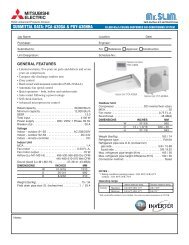
1 PART NAMES AND FUNCTIONS<br />
Indoor unit<br />
OCH515<br />
Filter Air intake<br />
Louver Air outlet Vane<br />
2
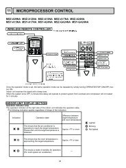
Wireless remote controller<br />
display<br />
OPERATION MODE display<br />
Operation mode display indicates which<br />
operation mode is in effect.<br />
display<br />
The vertical direction of air flow is indicated.<br />
display<br />
FAN SPEED display indicates which fan<br />
speed has been selected.<br />
ON/OFF button<br />
The unit is turned ON and OFF alternately<br />
each time the button is pressed.<br />
FAN SPEED SELECT button<br />
Used to change the fan speed.<br />
MODE SELECT button<br />
Used to switch the operation mode between<br />
cooling, drying, fan, heating and auto mode.<br />
In case the outdoor unit is cool only type,<br />
the heating and auto mode are not<br />
available.<br />
CHECK-TEST RUN button<br />
Only press this button to perform an<br />
inspection check or test operation.<br />
Do not use it for normal operation.<br />
VANE CONTROL button<br />
Used to change the air flow direction.<br />
OCH515<br />
CHECK TEST RUN display<br />
CHECK and TEST RUN display indicate that<br />
the unit is being checked or test-run.<br />
MODEL SELECT display<br />
Blinks when model is selected.<br />
ON/OFF TEMP<br />
MODE<br />
CHECK<br />
TEST RUN<br />
CHECK TEST RUN<br />
MODEL SELECT<br />
NOT AVAILABLE<br />
FAN<br />
VANE<br />
LOUVER<br />
SET RESET CLOCK<br />
3<br />
°F<br />
°C<br />
AMPM<br />
AMPM<br />
AUTO STOP<br />
AUTO START<br />
h<br />
min<br />
display<br />
Lights up while the signal is transmitted to<br />
the indoor unit when the button is pressed.<br />
display<br />
SET TEMP. display indicates the set desired<br />
temperature.<br />
CLOCK display<br />
Displays the current time.<br />
TIMER display<br />
Displays when in timer operation or when<br />
setting timer.<br />
“ ” “ ” display<br />
Displays the order of timer operation.<br />
“ ” “ ” display<br />
Displays whether timer is on or off.<br />
button<br />
SET TEMPERATURE button sets any desired<br />
room temperature.<br />
TIMER CONTROL buttons<br />
AUTO STOP (OFF timer): when this switch is<br />
set, the air conditioner will be automatically<br />
stopped at the preset time.<br />
AUTO START (ON timer): when this switch is<br />
set, the air conditioner will be automatically<br />
started at the preset time.<br />
h and min buttons<br />
Buttons used to set the “hour and minute” of<br />
the current time and timer settings.<br />
LOUVER button<br />
Changes left/right airflow direction.<br />
(Not available for this model.)<br />
CLOCK button<br />
RESET button<br />
SET button
Wired remote controller<br />
Note:<br />
The phrase "Wired remote controller" in this manual refers only to the PAR-21MAA.<br />
If you need any information for the other remote controller, please refer to either the installation manual or initial setting manual which are included in<br />
remote controller's box.<br />
Display Section<br />
For purposes of this explanation,<br />
all parts of the display are shown<br />
as lit. During actual operation, only<br />
the relevant items will be lit.<br />
Identifies the current operation<br />
Shows the operating mode, etc.<br />
*Multilanguage display is available.<br />
“Centrally Controlled” indicator<br />
Indicates that operation from the<br />
remote controller has been prohibited<br />
by a master controller.<br />
“Timer is Off” indicator<br />
Indicates that the timer is off.<br />
Temperature Setting<br />
Shows the target temperature.<br />
Operation Section<br />
Temperature setting buttons<br />
Down<br />
Up<br />
Timer Menu button<br />
(Monitor/Set button)<br />
Mode button (Return button)<br />
Set Time buttons<br />
Back<br />
Ahead<br />
Timer On/Off button<br />
(Set Day button)<br />
Opening the<br />
cover<br />
OCH515<br />
Day-of-Week<br />
Shows the current day of the week.<br />
Time/Timer Display<br />
Shows the current time, unless the simple or Auto Off<br />
timer is set.<br />
If the simple or Auto Off timer is set, the time to be<br />
switched off is shown.<br />
PAR-21MAA<br />
°F°C<br />
TIME SUN MON TUE WED THU FRI SAT<br />
TIMER<br />
Hr ON<br />
AFTER<br />
AFTER OFF<br />
ERROR CODE<br />
°F°C<br />
ONLY1Hr.<br />
Up/Down Air Direction indicator<br />
The indicator shows the direction<br />
of the outcoming airflow.<br />
“One Hour Only” indicator<br />
Displayed if the airflow is set to<br />
Low or downward during COOL<br />
or DRY mode. (Operation varies<br />
according to model.)<br />
The indicator goes off in one hour,<br />
at which time the airflow direction<br />
also changes.<br />
TEMP.<br />
MENU<br />
BACK MONITOR/SET DAY<br />
CLOCK<br />
ON/OFF<br />
4<br />
FUNCTION<br />
FILTER<br />
WEEKLY<br />
SIMPLE<br />
AUTO OFF<br />
Room Temperature display<br />
Shows the room temperature. The room<br />
temperature display range is 46–102°F.<br />
The display blinks if the temperature<br />
is less than 46°F or 102°F or more.<br />
Louver display<br />
Indicates the action of the swing louver.<br />
Does not appear if the louver is not<br />
running.<br />
(Power On indicator)<br />
Indicates that the power is on.<br />
ON/OFF<br />
FILTER<br />
OPERATION CLEAR<br />
CHECK TEST<br />
Built-in temperature sensor<br />
“Sensor” indication<br />
Displayed when the remote controller<br />
sensor is used.<br />
“Locked” indicator<br />
Indicates that remote controller buttons<br />
have been locked.<br />
“Clean The Filter” indicator<br />
To be displayed on when it is time to<br />
clean the filter.<br />
Timer indicators<br />
The indicator comes on if the corresponding<br />
timer is set.<br />
Fan Speed indicator<br />
Shows the selected fan speed.<br />
Ventilation indicator<br />
Appears when the unit is running in<br />
Ventilation mode.<br />
ON/OFF button<br />
Fan Speed button<br />
Filter button<br />
( button)<br />
Test Run button<br />
Check button (Clear button)<br />
Airflow Up/Down button<br />
Louver button<br />
( Operation button)<br />
To return operation<br />
number<br />
Ventilation button<br />
( Operation button)<br />
To go to next operation<br />
number
2 SPECIFICATION<br />
2-1. Specifi cations<br />
<strong>Service</strong> Ref.<br />
Power source<br />
Cooling capacity<br />
kW<br />
4.4<br />
(Nominal)<br />
Btu/h<br />
15,000<br />
Power input kW<br />
0.03<br />
Current input A<br />
0.30<br />
Heating capacity<br />
kW<br />
5.0<br />
(Nominal )<br />
Btu/h<br />
17,000<br />
Power input kW<br />
0.03<br />
Current input A<br />
0.30<br />
External finish<br />
External dimension H × W × D mm<br />
in.<br />
Net weight<br />
kg (lb)<br />
Heat exchanger<br />
Fan<br />
Type × Quantity<br />
External<br />
Pa<br />
static press. mmH2O<br />
Motor type<br />
Motor output kW<br />
Driving mechanism<br />
Airflow rate m<br />
(Low-Mid-High)<br />
Noise level (Low-Mid-High)<br />
(measured in anechoic room)<br />
Insulation material<br />
Air filter<br />
Protection device<br />
Refrigerant control device<br />
Connectable outdoor unit<br />
Diameter of Liquid<br />
refrigerant pipe<br />
Gas<br />
Field drain pipe size<br />
Standard<br />
Document<br />
attachment Accessory<br />
Optional parts External heater adapter<br />
Remarks<br />
Installation<br />
3 PKFY-P08NHMU-E2 PKFY-P12NHMU-E2 PKFY-P15NHMU-E2 PKFY-P18NHMU-E2<br />
1-phase 208-230V 60Hz<br />
*1<br />
2.3<br />
3.5<br />
5.3<br />
*1<br />
8,000<br />
12,000<br />
18,000<br />
0.03<br />
0.03<br />
0.03<br />
0.30<br />
0.30<br />
0.30<br />
*2<br />
2.6<br />
4.0<br />
5.9<br />
*2<br />
9,000<br />
13,500<br />
20,000<br />
0.03<br />
0.03<br />
0.03<br />
0.30<br />
0.30<br />
0.30<br />
Plastic, MUNSELL (1.0Y 9.2/0.2)<br />
295 × 898 × 249<br />
11-5/8" × 35-3/8" × 9-13/16"<br />
13 (29)<br />
Cross fin (Aluminum fin and copper tube)<br />
Line flow fan × 1<br />
0<br />
0<br />
DC motor<br />
0.030<br />
Direct-drive<br />
/min 9 - 10.5 - 11.7<br />
9 - 10.5 - 11.7<br />
9 - 10.5 - 11.7<br />
9 - 10.5 - 12<br />
L/s<br />
150 - 175 - 195<br />
150 - 175 - 195<br />
150 - 175 - 195<br />
150 - 175 - 200<br />
cfm<br />
320 - 370 - 413<br />
320 - 370 - 413<br />
320 - 370 - 413<br />
320 - 370 - 425<br />
dB <br />
34 - 39 - 43<br />
34 - 39 - 43<br />
34 - 39 - 43<br />
36 - 41 - 45<br />
Polyethylene sheet<br />
PP honeycomb<br />
Fuse<br />
LEV<br />
R410A, R22 CITY MULTI<br />
(R410A) mm (in.) ø6.35 (ø1/4") Flare ø6.35 (ø1/4") Flare ø6.35 (ø1/4") Flare ø6.35 (ø1/4") Flare<br />
(R22)<br />
ø6.35 (ø1/4") Flare ø6.35 (ø1/4") Flare ø6.35 (ø1/4") Flare ø9.52 (ø3/8") Flare *3<br />
(R410A) mm (in.) ø12.7 (ø1/2") Flare ø12.7 (ø1/2") Flare ø12.7 (ø1/2") Flare ø12.7 (ø1/2") Flare<br />
(R22)<br />
ø12.7 (ø1/2") Flare ø12.7 (ø1/2") Flare ø12.7 (ø1/2") Flare ø15.88 (ø5/8") Flare *3<br />
mm (in.)<br />
I.D. 16mm (5/8")<br />
Installation <strong>Manual</strong>, Instruction Book<br />
— —<br />
—<br />
—<br />
PAC-YU25HT<br />
Details on foundation work, insulation work, electrical wiring, power source switch, and other items shall be referred to<br />
the Installation <strong>Manual</strong>.<br />
Note :<br />
*1 Nominal cooling conditions<br />
*2 Nominal heating conditions<br />
Indoor : 80°FDB/67°FWB (26.7°CDB/19.4°CWB) 70°FDB(21°CDB)<br />
Outdoor : 95°FDB (35°CDB)<br />
47°FDB/43°FWB (8.3°CDB/6.1°CWB)<br />
Pipe length : 25 ft. (7.6 m)<br />
25 ft. (7.6 m)<br />
Level difference : 0 ft (0 m)<br />
0 ft (0 m)<br />
* Due to continuing improvement, above specification may be subject to change without notice.<br />
OCH515<br />
5<br />
*3 Connect the joint<br />
(purchased locally) for R22<br />
Unit converter<br />
kcal/h = kW × 860<br />
Btu/h = kW × 3,412<br />
cfm = m3 /min × 35.31<br />
lb = kg/0.4536<br />
*Above specification data is<br />
subject to rounding variation.
2-2. Electrical parts specifi cations<br />
<strong>Service</strong> Ref.<br />
Parts name<br />
Room temperature<br />
thermistor<br />
Liquid pipe thermistor<br />
Gas pipe thermistor<br />
Fuse<br />
(Indoor controller board)<br />
Fan motor<br />
Vane motor<br />
(with limit switch)<br />
Linear expansion valve<br />
Power supply terminal<br />
block<br />
Transmission terminal<br />
block<br />
MA remote controller<br />
terminal block<br />
2-3. Sound levels<br />
* Measured in anechoic room.<br />
Symbol<br />
TH21<br />
TH22<br />
TH23<br />
TH24<br />
FUSE<br />
MF<br />
MV<br />
LEV<br />
TB2<br />
TB5<br />
TB15<br />
PKFY-P08, 12, 15NHMU-E2<br />
External static pressure : 0Pa<br />
Power source : 208,230V, 60Hz<br />
OCTAVE BAND PRESSURE LEVEL (dB) 0dB = 20Pa<br />
3.3 ft.<br />
(1m)<br />
Measurement location<br />
2-4. NC curves<br />
70.0<br />
65.0<br />
60.0<br />
55.0<br />
50.0<br />
45.0<br />
40.0<br />
35.0<br />
30.0<br />
25.0<br />
3.3 ft.<br />
(1m)<br />
20.0<br />
15.0<br />
Approximate minimum<br />
audible limit on<br />
continuous noise<br />
NC20<br />
10.0<br />
63 125 250 500 1k 2k 4k 8k<br />
OCTAVE BAND CENTER FREQUENCIES(Hz)<br />
OCH515<br />
High speed<br />
Middle speed<br />
Low speed<br />
PKFY-P08NHMU-E2 PKFY-P12NHMU-E2 PKFY-P15NHMU-E2<br />
Resistance 30°F/15.8k, 50°F/9.6k, 70°F/6.0k, 80°F/4.8k, 90°F/3.9k, 100°F/3.2k<br />
Resistance 30°F/15.8k, 50°F/9.6k, 70°F/6.0k, 80°F/4.8k, 90°F/3.9k, 100°F/3.2k<br />
Resistance 30°F/15.8k, 50°F/9.6k, 70°F/6.0k, 80°F/4.8k, 90°F/3.9k, 100°F/3.2k<br />
NC60<br />
NC50<br />
NC40<br />
NC30<br />
70.0<br />
65.0<br />
60.0<br />
55.0<br />
50.0<br />
45.0<br />
40.0<br />
35.0<br />
30.0<br />
25.0<br />
Approximate minimum<br />
20.0 audible limit on<br />
continuous noise<br />
15.0<br />
6<br />
250V 3.15A<br />
8-Pole Output 30W / RCOJ30-CK<br />
MSFBC20 DC12V<br />
DC12V Stepping motor drive<br />
Port 3.2 (0~2000pulse)<br />
(L1, L2, GR) 250V 20A<br />
(M1, M2, S) 250V 20A<br />
(1, 2) 250V 10A<br />
<strong>Service</strong> Ref.<br />
PKFY-P08NHMU-E2<br />
PKFY-P12NHMU-E2<br />
PKFY-P15NHMU-E2<br />
PKFY-P18NHMU-E2<br />
PKFY-P18NHMU-E2<br />
External static pressure : 0Pa<br />
Power source : 208,230V, 60Hz<br />
OCTAVE BAND PRESSURE LEVEL (dB) 0dB = 20Pa<br />
High speed<br />
Low speed<br />
10.0<br />
63 125 250 500 1k 2k 4k 8k<br />
OCTAVE BAND CENTER FREQUENCIES(Hz)<br />
NC60<br />
NC50<br />
NC40<br />
NC30<br />
NC20<br />
PKFY-P18NHMU-E2<br />
Sound level at anechoic room : Low-Middle-High<br />
Sound level dB (A)<br />
34-39-43<br />
36-41-45
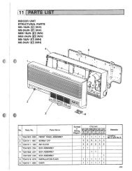
3<br />
OUTLINES AND DIMENSIONS<br />
PKFY-P08NHMU-E2<br />
PKFY-P12NHMU-E2<br />
PKFY-P15NHMU-E2<br />
PKFY-P18NHMU-E2<br />
Sleeve<br />
(purchased locally)<br />
7/16(12.5)<br />
OCH515<br />
2-1/2~3-1/8<br />
(65~80)<br />
A<br />
1-11/16(43)<br />
D<br />
Through hole<br />
2-1/2~3-1/8<br />
(65~80)<br />
Knockout hole for piping<br />
2-3/16(56)<br />
Left side<br />
Knockout hole<br />
for left piping<br />
C<br />
1-3/4(46)<br />
2-3/16(56)<br />
3/16(6)<br />
77-3/16(5.1)<br />
Tapping<br />
screw hole<br />
0<br />
5/8(16)<br />
1-1/16(28.5)<br />
1-9/16(41)<br />
3-1/16(78.5)<br />
3-9/16(91)<br />
4-1/16(103.5)<br />
4-9/16(116)<br />
6-1/2(166)<br />
7(178.5)<br />
8(203.5)<br />
9-1/8(232.5)<br />
9-15/16(253.5)<br />
1-11/16(43)<br />
Wall hole for<br />
left rear piping<br />
2-11/16(69)<br />
7-3/4(197)<br />
Knockout hole<br />
for lower piping<br />
11-9/16(295)<br />
5/16(8)<br />
2-3/16(56)<br />
3/16(6)<br />
2-1/8<br />
(55)<br />
4-5/16(9) Bolt hole<br />
14-5/8(372.3)<br />
14(356.3)<br />
12-7/8(327.5)<br />
11-7/16(291.5)<br />
10-3/8(265)<br />
8-13/16(225)<br />
7-13/16(200)<br />
17-5/8(449)<br />
1-3/4(46)<br />
2-5/16(60)<br />
C<br />
15-1/2(394)<br />
Vane(auto)<br />
10-15/16(278.3)<br />
9-5/16(238)<br />
8-3/8(213)<br />
6-13/16(174)<br />
D<br />
1-11/16(43)<br />
1-11/16(43)<br />
15-3/16(387) 7-1/2(192)<br />
Louver(manual)<br />
2-5/16(59)<br />
B<br />
Front side(Grille open)<br />
4-7/8(125)<br />
27-1/16(688)<br />
17-15/16(457)Gas pipe<br />
21-3/16(539)Liquid pipe<br />
7<br />
2-3/4(70)<br />
23-9/16(599)<br />
35-5/16(898)<br />
0<br />
9/16(15)<br />
0<br />
9/16(15)<br />
0<br />
2-1/4(58)<br />
Knockout hole for<br />
rear piping<br />
2-3/4×12-3/16(70×310)<br />
2-3/4(70)<br />
5/32(3.8)<br />
4-7/8(125)<br />
Center measurement hole 3/32(2.5)<br />
Mount board<br />
4-1/2(115)<br />
5-1/2(140)<br />
6-9/16(167)<br />
7-1/16(180.3)<br />
7-9/16(193.5)<br />
7-13/16(200)<br />
8-13/16(225)<br />
9-5/16(238)<br />
10-3/8(265)<br />
11-7/16(291.5)<br />
12-7/8(237.5)<br />
14(356.3)<br />
14-5/8(372.3)<br />
11-1/16(281)<br />
6-5/8(169)<br />
6-3/16(158)<br />
24(610)Drain hose 7-3/16(184)<br />
Under side<br />
24-1/16(612)<br />
Min.1/4(7)<br />
Knockout hole<br />
for lower piping<br />
Operation lamp<br />
Required space(Indoor unit)<br />
Min.1-31/32(50)<br />
B<br />
Top side<br />
Front side<br />
6-1/16(155)<br />
Wall hole for<br />
right rear piping<br />
Refrigerart<br />
Piping<br />
Liquid pipe<br />
Gas pipe<br />
Drain hose<br />
Indoor unit outline<br />
17-5/8(449)<br />
Min.8-5/8<br />
(220)<br />
Terminal block for power supply<br />
Terminal block for transmission<br />
Terminal block for<br />
MA-remote controller<br />
Emergency operation switch<br />
(cooling/heating)<br />
DEFROST/STAND BY lamp<br />
Receiver<br />
13/16(21.8)<br />
0<br />
3/4(20)<br />
1-1/4(32.7)<br />
2-1/16(53.5)<br />
2-9/16(66)<br />
5(128.5)<br />
6(153.5)<br />
9-1/16(231.5)<br />
10-3/4(273.2)<br />
Knockout hole<br />
for right piping<br />
Air inlet<br />
Air inlet<br />
Right side<br />
Min.5-7/8(150)<br />
Mount board<br />
9-3/4(249)<br />
Air outlet<br />
Unit : inch (mm)<br />
A<br />
1/4F (6.35)<br />
1/2F (12.7)<br />
5/8 (16) I.D<br />
3/16(5)<br />
Min.1-31/32(50)<br />
Min.9-13/16(250)
4<br />
WIRING DIAGRAM<br />
PKFY-P08NHMU-E2<br />
PKFY-P12NHMU-E2<br />
PKFY-P15NHMU-E2<br />
PKFY-P18NHMU-E2<br />
RED<br />
MF<br />
MS<br />
3~<br />
BLK<br />
WHT<br />
YLW<br />
BLU<br />
1 3 6<br />
FAN<br />
CNMF<br />
(WHT)<br />
OCH515<br />
1<br />
CNP<br />
(BLU)<br />
1 3<br />
FUSE<br />
X1<br />
<br />
TB2<br />
RED<br />
L1<br />
BLU<br />
L2<br />
GRN/YLW<br />
GR<br />
CND<br />
(BLK)<br />
5<br />
M-NET<br />
CN2M (BLU)<br />
ON<br />
OFF<br />
SW2 SW4 SW3<br />
1 2 123456 1234 12345678<br />
BLU<br />
BLU<br />
SYMBOL NAME<br />
SYMBOL NAME<br />
I.B INDOOR CONTROLLER BOARD TH21 THERMISTOR ROOM TEMP. DETECTION<br />
CN24 CONNECTOR EXTERNAL HEATER<br />
(32°F/15k,77°F/5.4kΩ)<br />
CN32<br />
REMOTE SWITCH TH22<br />
PIPE TEMP. DETECTION / LIQUID<br />
CN51<br />
CENTRALLY CONTROL<br />
(32°F/15k,77°F/5.4kΩ)<br />
CN52<br />
REMOTE INDICATION TH23<br />
PIPE TEMP. DETECTION / GAS1<br />
BZ1 BUZZER<br />
(32°F/15k,77°F/5.4kΩ)<br />
FUSE FUSE (T3.15AL 250V)<br />
TH24<br />
PIPE TEMP. DETECTION / GAS2<br />
LED1 POWER SUPPLY (I.B)<br />
(32°F/15k,77°F/5.4kΩ)<br />
LED2 POWER SUPPLY (I.B)<br />
A.B ADDRESS BOARD<br />
SW2 SWITCH CAPACITY CODE<br />
SWA SWITCH FAN SPEED SELECTOR<br />
SW3<br />
MODE SELECTION<br />
SW1<br />
MODE SELECTION<br />
SW4<br />
MODEL SELECTOR<br />
SW11<br />
ADDRESS SETTING 1s DIGIT<br />
SWE<br />
DRAIN PUMP (TEST MODE) SW12<br />
ADDRESS SETTING 10ths DIGIT<br />
X1 AUX.RELAY DRAIN PUMP<br />
SW14 BRANCH No.<br />
LEV LINEAR EXPANSION VALVE<br />
S.B SWITCH BOARD<br />
MF FAN MOTOR<br />
SWE1 EMERGENCY OPERATION(HEAT)<br />
MV VANE MOTOR<br />
SWE2 EMERGENCY OPERATION(COOL)<br />
TB2 TERMINAL POWER SUPPLY<br />
W.B PCB FOR WIRELESS REMOTE CONTROLLER<br />
TB5 BLOCK TRANSMISSION<br />
LED1 LED(OPERATION INDICATOR:GREEN)<br />
TB15<br />
MA-REMOTE CONTROLLER LED2 LED(OPERATION FOR HEATING :ORANGE )<br />
RU RECEIVING UNIT<br />
RED<br />
BLU<br />
BLK<br />
See fig:1<br />
PULL<br />
BOX<br />
TO NEXT<br />
INDOOR<br />
UNIT<br />
MV LEV<br />
M<br />
M<br />
GRN<br />
YLW<br />
ORN<br />
RED<br />
BRN<br />
FUSE<br />
(16A) BREAKER<br />
(16A)<br />
SWE<br />
OFF ON<br />
3 1<br />
LDSWE (A)<br />
(BLU)<br />
1 3<br />
ORN<br />
POWER SUPPLY<br />
208/230V 60Hz<br />
ORN<br />
BRN<br />
RED<br />
BLU<br />
ORN<br />
YLW<br />
WHT<br />
8<br />
3<br />
6<br />
I.B<br />
CN52<br />
(GRN)<br />
5 1<br />
5 VANE 1 6<br />
CN151<br />
(WHT)<br />
BZ1<br />
LED1<br />
CNRU<br />
(WHT)<br />
1 6 LEV<br />
CN60<br />
(YLW)<br />
5 CN51 1<br />
(WHT)<br />
1<br />
CN24<br />
(YLW)<br />
2 1<br />
FLOAT SW<br />
CN4F<br />
(WHT)<br />
4 1<br />
GAS2<br />
CN2G<br />
(BLK)<br />
2 1<br />
CN32<br />
(WHT)<br />
8<br />
ADDRESS<br />
CN81<br />
(RED)<br />
3<br />
1<br />
1<br />
LED2<br />
LIQUID/GAS1<br />
CN44<br />
(WHT)<br />
ADDRESS 4 1<br />
CN42<br />
4(RED) 1 INTAKE<br />
CN20<br />
(RED) 2 1<br />
MA-REMOCON<br />
CN3A<br />
(BLU)<br />
TB15<br />
1<br />
2<br />
TB5 (SHIELD)<br />
M1<br />
M2<br />
S<br />
TO MA-REMOTE<br />
CONTROLLER<br />
DC8.7-13V<br />
TO OUTDOOR UNIT<br />
BC CONTROLLER<br />
REMOTE CONTROLLER<br />
DC24-30V<br />
t ○<br />
t ○<br />
t ○<br />
t ○<br />
LED2 LD101 (B)<br />
RU<br />
LED1<br />
W.B<br />
4<br />
The black square ( ) indicates<br />
a switch position.<br />
<br />
Models SW2<br />
P08<br />
P12<br />
P15<br />
P18<br />
SWE1 SWE2<br />
S.B<br />
ON<br />
OFF<br />
123456<br />
ON<br />
OFF<br />
123456<br />
ON<br />
OFF<br />
123456<br />
ON<br />
OFF<br />
123456<br />
8<br />
ADDRESS<br />
CN43<br />
(RED)<br />
SW1<br />
3<br />
ON<br />
2<br />
OFF<br />
1<br />
1 2 3 45678910SWA<br />
ADDRESS<br />
CN82<br />
(RED)<br />
SW12 SW11 SW14<br />
A.B<br />
TH24<br />
TH23<br />
TH22<br />
TH21<br />
0 1 2 3 4 5 6 7 8 9<br />
10ths<br />
DIGIT<br />
0 1 2 3 4 5 6 7 8 9<br />
1s<br />
DIGIT<br />
NOTES:<br />
1.At servicing for outdoor unit, always follow the wiring diagram of outdoor unit.<br />
2.In case of using MA-Remote controller, please connect to TB15.<br />
(Remote controller wire is non-polar.)<br />
3.In case of using M-NET, please connect to TB5. (Transmission line is non-polar.)<br />
4.Symbol [S] of TB5 is the shield wire connection.<br />
5.Symbols used in wiring diagram above are, : terminal block, :connecter.<br />
6.The setting of the SW2 dip switches differs in the capacity. For the detail, refer to the fig:1.<br />
Use copper supply wires.<br />
LED on indoor board for service<br />
Mark Meaning Function<br />
Main power supply (Indoor unit: 208-230V)<br />
LED1 Main power supply<br />
Power on → Iamp is lit<br />
Power supply for Power supply for MA-Remote controller<br />
LED2<br />
MA-Remote controller on → Iamp is lit<br />
BRANCH<br />
No.<br />
0123456789AB CDEF<br />
LD SWE (B)
5 REFRIGERANT SYSTEM DIAGRAM<br />
PKFY-P08NHMU-E2<br />
PKFY-P12NHMU-E2<br />
PKFY-P15NHMU-E2<br />
PKFY-P18NHMU-E2<br />
OCH515<br />
Heat exchanger<br />
Room temparature thermistor TH21<br />
Item<br />
<strong>Service</strong> Ref.<br />
Gas pipe<br />
Liquid pipe<br />
Gas pipe thermistor TH23<br />
Gas pipe thermistor TH24<br />
9<br />
Strainer (#50mesh)<br />
Liquid pipe thermistor TH22<br />
Gas pipe<br />
Liquid pipe<br />
Linear expansion valve<br />
Strainer1 (#50mesh)<br />
Strainer2 (#100mesh)<br />
Strainer (#100mesh)<br />
PKFY-P08,12,15,18NHMU-E2<br />
12.7(1/2)<br />
6.35(1/4)<br />
Unit : mm (inch)<br />
Flare connection
6 MICROPROCESSOR CONTROL<br />
INDOOR UNIT CONTROL<br />
6-1. COOL OPERATION<br />
PAR-21MAA<br />
TEMP.<br />
MENU<br />
ûFûC<br />
BACK MONITOR/SET DAY<br />
TIME SUN MON TUE WED THU FRI SAT<br />
TIMER<br />
Hr ON<br />
AFTER<br />
AFTER OFF<br />
ERROR CODE<br />
ûFûC<br />
FUNCTION<br />
FILTER<br />
WEEKLY<br />
SIMPLE<br />
ONLY1Hr.<br />
AUTO OFF<br />
CLOCK<br />
ON/OFF<br />
ON/OFF<br />
FILTER<br />
OPERATION CLEAR<br />
CHECK TEST<br />
<br />
Press POWER ON/OFF button.<br />
Press the operation MODE button to display COOL.<br />
Press the TEMP. button to set the desired temperature.<br />
NOTE: The set temperature changes 2°F when the or button is<br />
pressed one time. Cooling 67 to 87°F<br />
Control modes Control details<br />
1. Thermostat 1-1. Thermostat function (Function to prevent restarting for 3 minutes)<br />
function<br />
• Room temperature desired temperature + 2°F ···Thermo ON<br />
• Room temperature desired temperature ···Thermo OFF<br />
2. Fan<br />
3. Vane<br />
(up/down vane change)<br />
OCH515<br />
1-2. Anti-freezing control<br />
Detected condition : When the liquid pipe temp. (TH22) is 32°F or less in 16<br />
minutes from compressors start up, anti-freezing control<br />
starts and the thermo OFF.<br />
Released condition : The timer which prevents reactivating is set for 3 minutes,<br />
and anti-freezing control is cancelled when any one of the<br />
following conditions is satisfied.<br />
Liquid pipe temp. (TH22) turns 50°F or above.<br />
The condition of the thermo OFF has become complete<br />
by thermostat, etc.<br />
The operation modes became mode other than COOL.<br />
The operation stopped.<br />
By the remote controller setting (switch of 3 speeds+Auto)<br />
Type<br />
3 speeds + Auto type<br />
Fan speed notch<br />
[Low], [Mid], [High], [Auto]<br />
When [Auto] is set, fan speed is changed depending on the value of:<br />
Room temperature - Desired temperature<br />
(1) Initial setting: Start at COOL mode and horizontal vane.<br />
(2) Vane position:<br />
Horizontal →Downward A →Downward B →Downward C→Downward D→Swing→Auto<br />
→<br />
(3) Restriction of the downward vane setting<br />
When setting the downward vane A, B, C or D in [Mid], [Low] or [Auto] of the fan<br />
speed notch, the vane changes to horizontal position after 1 hour have passed.<br />
10<br />
Remarks<br />
· "ONLY 1 Hr"<br />
appears on the<br />
wired remote<br />
controller.
6-2. DRY OPERATION<br />
PAR-21MAA<br />
Control modes Control details<br />
1. Thermostat<br />
function<br />
2. Fan<br />
TEMP.<br />
MENU<br />
BACK MONITOR/SET DAY<br />
3. Vane<br />
(up/down vane change)<br />
OCH515<br />
ûFûC<br />
TIME SUN MON TUE WED THU FRI SAT<br />
TIMER<br />
Hr ON<br />
AFTER<br />
AFTER OFF<br />
ERROR CODE<br />
ûFûC<br />
FUNCTION<br />
FILTER<br />
WEEKLY<br />
SIMPLE<br />
ONLY1Hr.<br />
AUTO OFF<br />
CLOCK<br />
ON/OFF<br />
ON/OFF<br />
FILTER<br />
OPERATION CLEAR<br />
CHECK TEST<br />
1-1. Thermostat function (Function to prevent restarting for 3 minutes)<br />
Setting the Dry thermo by the thermostat signal and the room temperature (TH21).<br />
Dry thermo ON Room temperature desired temperature + 2°F<br />
Dry thermo OFF Room temperature desired temperature<br />
Room<br />
temperature<br />
Over 64°F<br />
Less than 64°F<br />
1-2. Freeze prevention control<br />
No control function<br />
3 min. passed since starting operation<br />
Thermostat signal Room temperature (T1)<br />
ON<br />
OFF<br />
Indoor fan operation controlled depending on the compressor conditions.<br />
11<br />
T1 83°F<br />
83°F > T1 79°F<br />
79°F > T1 75°F<br />
75°F > T1<br />
Unconditional<br />
Dry thermo OFF<br />
Dry thermo Fan speed notch<br />
ON<br />
[Low]<br />
OFF<br />
Excluding the following<br />
Room temp. < 64°F<br />
Stop<br />
[Low]<br />
Note: Remote controller setting is not acceptable.<br />
Same control as COOL operation<br />
<br />
Press POWER ON/OFF button.<br />
Press the operation MODE button to display DRY.<br />
Press the TEMP. button to set the desired temperature.<br />
NOTE: The set temperature changes 2°F when the or button is<br />
pressed one time. Dry 67 to 87°F<br />
Dry thermo<br />
ON<br />
time (min)<br />
Dry thermo<br />
OFF<br />
time (min)<br />
9 3<br />
7 3<br />
5 3<br />
3 3<br />
3<br />
10<br />
Remarks
6-3. FAN OPERATION<br />
PAR-21MAA<br />
Control modes Control details<br />
1. Fan<br />
TEMP.<br />
MENU<br />
ûFûC<br />
BACK MONITOR/SET DAY<br />
CLOCK<br />
ON/OFF<br />
2. Vane<br />
(up/down vane change)<br />
OCH515<br />
TIME SUN MON TUE WED THU FRI SAT<br />
TIMER<br />
Hr ON<br />
AFTER<br />
AFTER OFF<br />
ERROR CODE<br />
ûFûC<br />
FUNCTION<br />
FILTER<br />
WEEKLY<br />
SIMPLE<br />
ONLY1Hr.<br />
AUTO OFF<br />
ON/OFF<br />
FILTER<br />
OPERATION CLEAR<br />
CHECK TEST<br />
Set by remote controller.<br />
<br />
Press POWER ON/OFF button.<br />
Press the operation MODE button to display FAN.<br />
Type Fan speed notch<br />
3 speeds + Auto type [Low], [Mid], [High], [Auto]<br />
When [Auto] is set, fan speed becomes [Low].<br />
Same as the control performed during the COOL operation, but with no restriction<br />
on the vane's downward blow setting<br />
12<br />
Remarks<br />
· Same control<br />
as COOL<br />
operation
6-4. HEAT OPERATION<br />
PAR-21MAA<br />
Control modes Control details<br />
1. Thermostat<br />
function<br />
2. Fan<br />
TEMP.<br />
MENU<br />
BACK MONITOR/SET DAY<br />
OCH515<br />
ûFûC<br />
TIME SUN MON TUE WED THU FRI SAT<br />
TIMER<br />
Hr ON<br />
AFTER<br />
AFTER OFF<br />
ERROR CODE<br />
ûFûC<br />
FUNCTION<br />
FILTER<br />
WEEKLY<br />
SIMPLE<br />
ONLY1Hr.<br />
AUTO OFF<br />
CLOCK<br />
ON/OFF<br />
ON/OFF<br />
FILTER<br />
OPERATION CLEAR<br />
CHECK TEST<br />
1-1. Thermostat function (Function to prevent restarting for 3 minutes)<br />
• Room temperature desired temperature -2°F ···Thermo ON<br />
• Room temperature desired temperature ···Thermo OFF<br />
By the remote controller setting (switch of 3 speeds+Auto)<br />
Type<br />
3 speeds + Auto type<br />
When [Auto] is set, fan speed is changed depending on the value of:<br />
Desired temperature - Room temperature<br />
Give priority to under-mentioned controlled mode<br />
2-1. Hot adjust mode<br />
2-2. Residual heat exclusion mode<br />
2-3. Thermo OFF mode (When the compressor off by the thermostat)<br />
2-4. Cool air prevention mode (Defrosting mode)<br />
2-1. Hot adjust mode<br />
The fan controller becomes the hot adjuster mode for the following conditions.<br />
When starting the HEAT operation<br />
When the thermostat function changes from OFF to ON.<br />
When release the HEAT defrosting operation<br />
Hot adjust mode *1<br />
[Extra Low]<br />
[Low]<br />
A B<br />
C<br />
<br />
Press POWER ON/OFF button.<br />
Press the operation MODE button to display HEAT.<br />
Press the TEMP. button to set the desired temperature.<br />
NOTE: The set temperature changes 2°F when the or button is<br />
pressed one time. Heating 63 to 83°F.<br />
<br />
[DEFROST]<br />
The [DEFROST] symbol is only displayed during the defrost operation.<br />
[STANDBY]<br />
The [STANDBY] symbol is only displayed during the hot adjust mode.<br />
Fan speed notch<br />
[Low], [Mid], [High], [Auto]<br />
Set fan speed by the remote controller<br />
A: Hot adjust mode starts.<br />
B: 5 minutes have passed since the condition A or the indoor liquid pipe<br />
temperature turned 95°F or more.<br />
C: 2 minutes have passed since the condition B. (Terminating the hot adjust mode)<br />
2-2. Residual heat exclusion mode<br />
When the condition changes the auxiliary heater ON to OFF (thermostat or<br />
operation stop, etc), the indoor fan operates in [Low] mode for 1 minute.<br />
13<br />
Remarks<br />
*1 "STAND BY"<br />
will be displayed<br />
during the hot<br />
adjust mode.<br />
· This control is<br />
same for the<br />
model without<br />
auxiliary heater.<br />
To be continued on the next page.
From the preceding page<br />
Control modes Control details<br />
2. Fan<br />
3. Vane control<br />
(Up/down vane<br />
change)<br />
2-3. Thermo OFF mode<br />
When the thermostat function changes to OFF, the indoor fan operates in<br />
[Extra low].<br />
2-4. Heat defrosting mode<br />
The indoor fan stops.<br />
(1) Initial setting: OFF → HEAT···[last setting]<br />
When the last setting is [Swing] ··· [Downward D]<br />
When changing the mode from exception of HEAT to HEAT operation<br />
···[Downward D]<br />
(2) Vane position:<br />
Horizontal →Downward A →Downward B →Downward C→Downward D→Swing→Auto<br />
→<br />
(3) Restriction of vane position<br />
The vane is horizontally fixed for the following modes.<br />
(The control by the remote controller is temporally invalidated and control by<br />
the unit.)<br />
•Thermo OFF<br />
•Hot adjust [Extra low] mode<br />
•Heat defrost mode<br />
6-5. AUTO OPERATION [AUTOMATIC COOL/HEAT CHANGE OVER OPERATION]<br />
PAR-21MAA<br />
TEMP.<br />
MENU<br />
ûFûC<br />
BACK MONITOR/SET DAY<br />
Control modes Control details<br />
1. Initial value of<br />
operation mode<br />
2. Mode change<br />
3. COOL mode<br />
4. HEAT mode<br />
TIME SUN MON TUE WED THU FRI SAT<br />
TIMER<br />
Hr ON<br />
AFTER<br />
AFTER OFF<br />
ERROR CODE<br />
ûFûC<br />
FUNCTION<br />
FILTER<br />
WEEKLY<br />
SIMPLE<br />
ONLY1Hr.<br />
AUTO OFF<br />
CLOCK<br />
ON/OFF<br />
OCH515<br />
ON/OFF<br />
FILTER<br />
OPERATION CLEAR<br />
CHECK TEST<br />
HEAT mode for room temperature < Desired temperature<br />
COOL mode for room temperature Desired temperature<br />
(1) HEAT mode → COOL mode<br />
Room temperature Desired temperature + 3°F. or 3 min. has passed<br />
(2) COOL mode → HEAT mode<br />
Room temperature Desired temperature - 3°F. or 3 min. has passed<br />
Same control as cool operation<br />
Same control as heat operation<br />
14<br />
Remarks<br />
<br />
Press POWER ON/OFF button.<br />
Press the operation MODE button to display AUTO.<br />
Press the TEMP. button to set the desired temperature.<br />
NOTE: The set temperature changes 2°F when the or button is<br />
pressed one time. Automatic 67 to 83°F<br />
Remarks
7<br />
TROUBLESHOOTING<br />
7-1. HOW TO CHECK THE PARTS<br />
PKFY-P08, 12, 15, 18NHMU-E2<br />
Parts name Check points<br />
Room temperature<br />
thermistor (TH21)<br />
Liquid pipe temperature<br />
thermistor (TH22)<br />
Gas pipe temperature<br />
thermistor (TH23 ,24)<br />
Vane motor (MV)<br />
Red<br />
Yellow<br />
Brown<br />
Connect pin No.<br />
Fan motor (MF)<br />
M<br />
Orange<br />
Green<br />
<br />
Linear expansion<br />
valve (LEV) CN60<br />
White<br />
1<br />
Yellow<br />
2<br />
LEV<br />
Orange<br />
Blue<br />
Red<br />
3<br />
4<br />
5<br />
Brown<br />
6<br />
Disconnect the connector then measure the resistance with a tester.<br />
(At the ambient temperature 50°F~86°F)<br />
Normal<br />
4.3k~9.6k<br />
Abnormal<br />
Open or short<br />
Disconnect the connector then measure the resistance value with a tester.<br />
(Coil temperature 68°F)<br />
(1)-(5)<br />
White-Red<br />
Normal<br />
(2)-(6)<br />
Yellow-Brown<br />
200 ± 10%<br />
(3)-(5)<br />
Orange-Red<br />
15<br />
Refer to the next page for the details.<br />
Measure the resistance between the terminals with a tester. (Coil temperature 77°F)<br />
-<br />
Brown-Red<br />
Refer to 7-1-3.<br />
7-1-1. Thermistor<br />
<br />
Thermistor for<br />
lower temperature<br />
-<br />
Brown-Orange<br />
Normal<br />
350 ± 7%<br />
-<br />
Brown-Yellow<br />
Φ4<br />
Φ3<br />
Φ2<br />
Φ1<br />
Abnormal<br />
-<br />
Brown-Green Open or short<br />
Abnormal<br />
(4)-(6)<br />
Blue-Brown Open or short<br />
Room temperature thermistor (TH21)<br />
Liquid pipe temperature thermistor (TH22)<br />
Gas pipe temperature thermistor (TH23) (TH24)<br />
Thermistor R0=15kΩ ± 3%<br />
Fixed number of B=3480 ± 2%<br />
Rt=15exp { 3480( 1<br />
1 ) }<br />
30°F 15.8kΩ<br />
50°F 9.6kΩ<br />
70°F 6.0kΩ<br />
80°F 4.8kΩ<br />
90°F 3.9kΩ<br />
100°F 3.2kΩ<br />
7-1-2. Liner expansion valve<br />
Operation summary of the linear expansion valve<br />
• Linear expansion valve open/close through stepping motor after receiving the pulse signal from the indoor controller board.<br />
• Valve position can be changed in proportion to the number of pulse signals.<br />
Controller board<br />
<br />
OCH515<br />
273+(t-32)/1.8<br />
Linear expansion valve<br />
M 6<br />
Brown<br />
5 2<br />
Yellow<br />
1<br />
3<br />
White Red Orange<br />
4<br />
Blue<br />
273<br />
Brown<br />
Red<br />
Blue<br />
Orange<br />
Yellow<br />
White<br />
Resistance (kΩ)<br />
Connector(CN60)<br />
50<br />
40<br />
30<br />
20<br />
10<br />
0<br />
-20 0 20 40 60 80 100 120<br />
Temperature (°F)<br />
6<br />
5<br />
4<br />
3<br />
2<br />
1<br />
< Thermistor for lower temperature ><br />
DC12V<br />
Drive circuit<br />
Φ4<br />
Φ3<br />
Φ2<br />
Φ1
Output<br />
(Phase)<br />
[1<br />
1<br />
ON<br />
Output<br />
2 3<br />
OFF OFF<br />
4<br />
ON<br />
Closing a valve : 1 → 2 → 3 → 4 → 1<br />
Opening a valve : 4 → 3 → 2 → 1 → 4<br />
The output pulse shifts in above order.<br />
[2<br />
[3<br />
[4<br />
ON<br />
OFF<br />
OFF<br />
ON<br />
ON<br />
OFF<br />
OFF<br />
ON<br />
ON<br />
OFF<br />
OFF<br />
ON<br />
Note:<br />
• When linear expansion valve operation stops, all output phase<br />
become OFF.<br />
• At phase interruption or when phase does not shift in order, motor<br />
does not rotate smoothly and motor will lock and vibrate.<br />
Linear expansion valve operation<br />
Open<br />
Valve position (capacity)<br />
Close<br />
A<br />
E<br />
Troubleshooting<br />
B<br />
Close<br />
Open<br />
Extra tightening (200~800 pulse)<br />
OCH515<br />
D<br />
Pulse number<br />
Symptom Check points<br />
Operation circuit<br />
failure of the micro<br />
processor<br />
Valve does not close<br />
completely.<br />
Wrong connection<br />
of the connector or<br />
contact failure<br />
C<br />
Disconnect the connector on the controller board, then connect<br />
LED for checking.<br />
6<br />
5<br />
4<br />
3<br />
2<br />
1<br />
16<br />
Countermeasures<br />
Exchange the indoor controller<br />
board at drive circuit<br />
failure.<br />
Linear expansion<br />
1kΩ LED<br />
When power is turned on, pulse signals will be output for 10<br />
seconds. There must be some defects in the operation circuit<br />
if the LED does not light while the signals are output or keeps<br />
lighting even after the signals stop.<br />
Motor will idle and make a ticking noise when the motor is Exchange the linear expan-<br />
valve mechanism is operated while the linear expansion valve is locked. sion valve.<br />
locked.<br />
This ticking sound is the sign of the abnormality.<br />
Short or breakage<br />
of the motor coil of<br />
the linear expansion<br />
valve<br />
Outdoor unit R410A model : 1400 pulse<br />
Outdoor unit R22 model : 2000 pulse<br />
Opening a valve all the way<br />
Measure the resistance between each coil (white-red, yellowbrown,<br />
orange-red, blue-brown) with a tester. It is normal if<br />
the resistance is in the range of 200Ω ±10%.<br />
To check the linear expansion valve, operate the indoor unit If large amount of refriger-<br />
in fan mode and at the same time operate other indoor units ant is leaked, exchange<br />
in cooling mode, then check the pipe temperature of the indoor unit by the<br />
outdoor multi controller board operation<br />
monitor. During fan operation, linear expan-<br />
Thermistor<br />
(Liquid pipe)<br />
Linear<br />
expansion<br />
valve<br />
• When the switch is turned on, 2200 pulse closing valve signal will<br />
be sent till it goes to point in order to define the valve position.<br />
• When the valve moves smoothly, there is no sound or vibration<br />
occurring from the linear expansion valves, however, when the<br />
pulse number moves from to or when the valve is locked,<br />
more sound can be heard than in a normal situation.<br />
• Sound can be detected by placing the ear against the screw driver<br />
handle while putting the screw driver tip to the linear expansion<br />
valve.<br />
sion valve is closed completely and if there<br />
is any leaking, detecting temperature of<br />
the thermistor will go lower. If the detected<br />
temperature is much lower than the temperature<br />
indicated in the remote controller,<br />
it means the valve is not closed all the way.<br />
It is not necessary to exchange the linear expansion valve, if<br />
the leakage is small and not affecting normal operation.<br />
Check the color of lead wire and missing terminal of the connector.<br />
Exchange the linear expansion<br />
valve.<br />
Disconnect the connector<br />
at the controller board,<br />
then check the continuity.
7-1-3. DC Fan motor (fan motor/indoor controller circuit board)<br />
Check method of DC fan motor (fan motor/indoor controller circuit board)<br />
Notes<br />
· High voltage is applied to the connecter (CNMF) for the fan motor. Pay attention to the service.<br />
· Do not pull out the connector (CNMF) for the motor with the power supply on.<br />
(It causes trouble of the indoor controller circuit board and fan motor.)<br />
Self check<br />
Symptom : The indoor fan cannot turn around.<br />
Wiring contact check<br />
Contact of fan motor connector (CNMF)<br />
Is there contact failure?<br />
NG<br />
Yes<br />
Wiring recovery<br />
No<br />
Power supply check (Remove the connector (CNMF))<br />
Measure the voltage in the indoor controller circuit board.<br />
TEST POINT : VDC (between 1 (+) and 3 (-) of the fan connector): VDC DC294~325V<br />
TEST POINT : VCC (between 4 (+) and 3 (-) of the fan connector): VCC DC15V<br />
Is the voltage normal?<br />
Yes<br />
Sensor signal check<br />
Measure the voltage between CNMF and DC 0V<br />
and DC 15V in the indoor controller circuit board.<br />
Does the voltage repeat<br />
DC 0V and DC 15V?<br />
Yes<br />
Replace indoor<br />
controller board<br />
Replace the fan motor.<br />
No<br />
Check the operation END<br />
OCH515<br />
OK<br />
No<br />
17<br />
Indoor controller board fuse check<br />
No<br />
Is the fuse normal? Replace the fuse<br />
Yes<br />
Replace indoor controller board.<br />
OK<br />
Check the operation END<br />
NG<br />
Replace the fan motor<br />
Replace the fan motor<br />
OK<br />
Check the operation END<br />
NG<br />
Replace indoor controller board.<br />
OK<br />
Check the operation END<br />
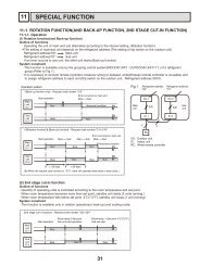
NG
7-2. Function of Dip switch<br />
PKFY-P08NHMU-E2 PKFY-P12NHMU-E2<br />
PKFY-P15NHMU-E2 PKFY-P18NHMU-E2<br />
Switch Pole Function<br />
SW1<br />
Mode<br />
selection<br />
SW2<br />
Capacity<br />
code<br />
switch<br />
SW3<br />
Function<br />
selection<br />
SW4<br />
Model<br />
selection<br />
1<br />
2<br />
3<br />
4<br />
5<br />
6<br />
7<br />
8<br />
9<br />
10<br />
1~6<br />
1<br />
2<br />
3<br />
4<br />
5<br />
6<br />
7<br />
8<br />
Operation by switch<br />
ON OFF<br />
Thermistor<br />
position<br />
Built-in remote controller Indoor unit<br />
Filter clogging detection Provide Not provide<br />
Filter cleaning sign 2,500 hr 100 hr<br />
Fresh air intake 2 Not effective Not effective<br />
Switching remote controller display Thermo ON signal indication Fan output indication<br />
Humidifier control Fan operation at Heating mode<br />
Thermo ON operation at<br />
heating mode<br />
Air flow set in case of heat<br />
Low 1 Extra low 1<br />
thermo OFF<br />
Setting air flow 1 Depends on SW1-7<br />
Auto restart function Effective Not effective<br />
Power ON/OFF by breaker Effective Not effective<br />
Heat pump/Cool only Cooling only Heat pump<br />
Not used<br />
Not used<br />
Models SW2 Models SW2<br />
P08<br />
P12<br />
ON<br />
OFF<br />
123456<br />
ON<br />
OFF<br />
123456<br />
Vane horizontal angle Second setting 1 First setting<br />
Changing the opening of linear<br />
expansion valve during thermo OFF Effective Not effective<br />
Heating 4 degree up Not effective Effective<br />
Target superheat setting 2 —<br />
P15<br />
P18<br />
ON<br />
OFF<br />
123456<br />
ON<br />
OFF<br />
123456<br />
— —<br />
— —<br />
Target subcool 2 — —<br />
In case of replacing the indoor controller board, make sure to set the<br />
switch to the initial setting, which is shown below.<br />
1~4 ON<br />
OFF<br />
OCH515<br />
1 2 3 4<br />
18<br />
—<br />
Effective<br />
timing<br />
Under<br />
suspension<br />
Before<br />
power<br />
supply<br />
ON<br />
Under<br />
suspension<br />
Before<br />
power<br />
supply<br />
ON<br />
Remarks<br />
Address board<br />
<br />
ON<br />
OFF<br />
1 2 3 4 5 6 7 8 9 10<br />
NOTE:<br />
1<br />
SW1-7<br />
OFF<br />
ON<br />
OFF<br />
ON<br />
SW1-8<br />
OFF<br />
OFF<br />
ON<br />
ON<br />
Indoor controller board<br />
<br />
ON<br />
OFF<br />
1 2 3 4 5 6 7 8<br />
Fan speed<br />
Extra low<br />
Low<br />
Setting air flow<br />
Stop<br />
2 It is impossible to intake<br />
the fresh air.<br />
Indoor controller board<br />
1 Second setting is same as<br />
first setting.<br />
2 Please do not use SW3-7,8<br />
as trouble might be caused<br />
by the usage condition.<br />
Indoor controller board
Switch<br />
SW11<br />
1s digit<br />
address<br />
setting<br />
SW12<br />
10ths digit<br />
address<br />
setting<br />
SW14<br />
Branch<br />
No.<br />
Setting<br />
J41, J42<br />
Wireless<br />
remote<br />
controller<br />
Pair No.<br />
Rotary Switch<br />
Rotary switch<br />
Jumper<br />
OCH515<br />
SW12<br />
0<br />
9<br />
8<br />
7<br />
6<br />
5<br />
10<br />
1<br />
2<br />
4<br />
E<br />
D<br />
C<br />
B<br />
3<br />
SW11<br />
0<br />
9<br />
8<br />
7<br />
6<br />
SW14<br />
A<br />
F<br />
9<br />
0<br />
8<br />
1<br />
7<br />
2<br />
3<br />
6<br />
4<br />
5<br />
5<br />
1<br />
1<br />
2<br />
4<br />
3<br />
Operation by switch<br />
How to set addresses<br />
Example : If address is "3", remain SW12<br />
(for over 10) at "0", and match SW11 (for 1 to 9)<br />
with "3".<br />
How to set branch numbers SW14 (Series R2 only)<br />
Match the indoor unit’s refrigerant pipe with<br />
the BC controller’s end connection number.<br />
Remain other than series R2 at "0".<br />
• To operate each indoor unit by each remote controller when installed 2 indoor<br />
units or more are near, Pair No. setting is necessary.<br />
Pair No. setting is available with the 4 patterns (Setting patterns A to D). .<br />
Make setting for J41, J42 of indoor controller board and the Pair No. of<br />
wireless remote controller.<br />
• You may not set it when operating it by one remote controller.<br />
Setting for indoor unit<br />
Cut jumper wire J41, J42 on the indoor controller board according to the<br />
table below.<br />
Wireless remote controller pair number:<br />
Setting operation<br />
1. Press the SET button (using a pointed implement). Check that the<br />
remote controller's display has stopped before continuing.<br />
MODEL SELECT flashes, and the model No. (3 digits) appears (steadily-lit).<br />
2. Press the MINUTE button twice. The pair number appears flashing.<br />
3. Press the temperature buttons to select the pair number to set.<br />
4. Press the SET button (using a pointed implement). The set pair number is<br />
displayed (steadily-lit) for 3 seconds, then disappears.<br />
Setting pattern<br />
Indoor controller<br />
jumper wire<br />
Pair No. of wireless<br />
remote controller<br />
J41 J42<br />
A<br />
— —<br />
0<br />
Initial setting<br />
B<br />
Cut —<br />
1<br />
—<br />
C<br />
— Cut<br />
2<br />
—<br />
D<br />
Cut Cut<br />
3<br />
—<br />
Pair No.4-9 of wireless remote controller is setting pattern D.<br />
19<br />
Effective<br />
timing<br />
Before<br />
power<br />
supply<br />
ON<br />
Under<br />
operation<br />
or<br />
suspension<br />
SET button<br />
Remarks<br />
Address board<br />
<br />
SW12 SW11<br />
9<br />
8<br />
7<br />
6<br />
0<br />
5<br />
1<br />
4<br />
E<br />
D<br />
C<br />
B<br />
A<br />
<br />
Pattern A<br />
ON/OFF TEMP<br />
MODE<br />
2<br />
FAN<br />
VANE<br />
CHECK LOUVER<br />
TEST RUN<br />
3<br />
F<br />
9<br />
0<br />
8<br />
1<br />
7<br />
MODEL SELECT<br />
9<br />
8<br />
SET RESET CLOCK<br />
7<br />
2<br />
3<br />
6<br />
6<br />
4<br />
5<br />
0<br />
5<br />
AUTO STOP<br />
AUTO START<br />
h<br />
1<br />
min<br />
2<br />
4<br />
3<br />
Address board<br />
<br />
SW14<br />
Pair No.<br />
Model No.<br />
Temperature<br />
button<br />
Minute<br />
button
7-3. TEST POINT DIAGRAM<br />
7-3-1. Indoor controller board<br />
PKFY-P08NHMU-E2<br />
PKFY-P12NHMU-E2<br />
PKFY-P15NHMU-E2<br />
PKFY-P18NHMU-E2<br />
CN2M<br />
Connect to the<br />
terminal block (TB5)<br />
(M-NET transmission<br />
connecting wire)<br />
24-30VDC (non-polar)<br />
Power supply from<br />
outdoor unit<br />
SW2<br />
Capacity setting<br />
SW4<br />
Model selection<br />
SW3<br />
Function setting<br />
Jumper wire J41, J42<br />
Pair No. setting for wireless<br />
remote controller<br />
LED2<br />
Power supply for<br />
MA-Remote controller<br />
CN3A<br />
Connected to the terminal<br />
block (TB15)<br />
(MA-Remote controller<br />
connecting wire)<br />
1 - 3 : 8.7-13V DC<br />
(Pin1 (+))<br />
OCH515<br />
CN32<br />
Remote switch<br />
CN20<br />
Room temperature<br />
thermistor (TH21)<br />
CN44<br />
Pipe temperature thermistor<br />
1-2 : Liquid (TH22)<br />
3-4 : Gas1 (TH23)<br />
CNMF<br />
Connect to the fan motor (MF)<br />
1-3 : DC294~325V<br />
4-3 : DC15V<br />
5-3 : DC0~6V<br />
6-3 : DC0 or DC15V (Stop)<br />
DC7.5V (Operation)<br />
(12VDC pulse)<br />
CN2G<br />
Pipe temperature<br />
thermistor<br />
Gas2 (TH24)<br />
CN24<br />
External heater<br />
12VDC (1 : +)<br />
CN52<br />
Remote indicator<br />
1-2: Status lamp 12VDC (1 : +)<br />
Fan motor output (SW1-5 OFF)<br />
Thermostat ON (SW1-5 ON)<br />
1-3: Cooling/Dry status lamp<br />
12VDC (1 : +)<br />
1-4: Heating status lamp<br />
12VDC (1 : +)<br />
20<br />
CN51<br />
Centrally control<br />
1-2 : Control signal<br />
12VDC pulse input (1 : +)<br />
3-4 : Operation indicator<br />
12VDC (3 : +)<br />
3-5 : Malfunction indicator<br />
12VDC (3 : +)<br />
FUSE<br />
3.15A 250V<br />
CND<br />
Power supply for<br />
indoor controller board<br />
1-3 : 208/230VAC<br />
LED1<br />
Main power supply<br />
(Indoor unit :<br />
208/230VAC)<br />
CN151<br />
Vane motor output<br />
12VDC pulse output<br />
CNRU<br />
Connect to the<br />
wireless remote<br />
controller board (W.B)<br />
LDSWE(A)<br />
Connect to the<br />
wireless remote<br />
controller board (S.B)<br />
CN60<br />
Liner expansion<br />
valve (LEV) output<br />
12VDC pulse output<br />
LD SWE (B)<br />
Connect to the indoor<br />
controller board (I.B)
8<br />
DISASSEMBLY PROCEDURE<br />
PKFY-P08NHMU-E2 PKFY-P12NHMU-E2<br />
PKFY-P15NHMU-E2 PKFY-P18NHMU-E2 Be careful when removing heavy parts.<br />
OPERATION PROCEDURE<br />
1. REMOVING THE LOWER SIDE OF THE INDOOR<br />
UNIT FROM THE INSTALLATION PLATE<br />
(1) Remove the front panel.<br />
(2) Insert the screw driver to the corner hole at both left and<br />
right side as shown in the figure 1.<br />
(3) Push it up, then pull down the lower side of indoor unit and<br />
remove the hook.<br />
2. REMOVING THE FRONT PANEL<br />
(1) Press and unlock the knobs on both sides of the front<br />
panel and lift the front panel until it is level. Pull the hinges<br />
forward to remove the front panel. (See Photo 2)<br />
(2) Move the horizontal vanes in a downward direction.<br />
(3) Remove the screw caps of the panel. Remove the screws.<br />
(See Photo 1)<br />
(4) Hold the lower part of both ends of the panel and pull it<br />
slightly toward you, and then remove the panel by pushing<br />
it upward.<br />
OCH515<br />
22<br />
Figure 1<br />
PHOTOS & ILLUSTRATIONS<br />
Be careful<br />
not to damage<br />
the airflow<br />
adjustment<br />
plate with the<br />
screw driver. Push<br />
Photo 1<br />
Photo 2<br />
Vanes<br />
Push<br />
Corner hole<br />
Screw caps<br />
Down<br />
Front panel
OPERATION PROCEDURE<br />
3. REMOVING THE INDOOR CONTROLLER BOARD<br />
AND WIRELESS CONTROLLER BOARD<br />
(1) Remove the front panel. (Refer to procedure 2)<br />
(2) Remove the electrical box covers (screw 4 × 12).<br />
(See Photo 3)<br />
(3) Remove the thermistor holder from the electrical box side<br />
cover. (See Photo 3)<br />
(4) Disconnect the connectors on the indoor controller board.<br />
(5) Remove the switch board cover.<br />
(6) Pull out the indoor controller board toward you, then<br />
disconnect the rest of connectors.<br />
Remove the indoor controller board and switch board.<br />
(7) Remove the holder of wireless controller board.<br />
(8) Disconnect the connector of wireless controller board and<br />
remove the wireless controller board from the holder.<br />
4. REMOVING THE ELECTRICAL BOX<br />
(1) Remove the front panel. (Refer to procedure 2)<br />
(2) Remove the electrical box covers. (See Photo 3)<br />
(3) Remove the nozzle assembly. (Refer to procedure 5)<br />
(4) Disconnect the transmission wiring of TB5.<br />
(5) Disconnect the power supply wiring of TB2.<br />
(6) Disconnect the wiring of MA-remote controller (TB15).<br />
(7) Disconnect the connectors on the indoor controller board.<br />
(8) Disconnect the connector for the ground wire. (See Photo 5)<br />
(9) Pull the disconnected lead wire out from the electrical box.<br />
(10) Remove the screw of electrical box. (See Photo 6)<br />
(11) Push up the upper fixture (See Photo 5) catch to remove<br />
the box, then pull the right fixture (See Photo 4) and<br />
remove it from the box fixture.<br />
OCH515<br />
23<br />
Photo 3<br />
Screw (top cover)<br />
Water cover<br />
Nozzle assembly<br />
Photo 4<br />
Terminal<br />
block (TB2)<br />
Terminal<br />
block (TB5)<br />
Terminal<br />
block (TB15)<br />
Photo 5<br />
Connector for<br />
ground wire<br />
Photo 6<br />
Screw (Electrical box)<br />
PHOTOS<br />
Screw (side cover)<br />
Switch holder Holder of wireless<br />
controller board<br />
Indoor controller board (I.B)<br />
Fixture<br />
(right)<br />
Electrical box<br />
cover (top)<br />
Room temp. thermistor (TH21)<br />
Electrical box<br />
cover (side)<br />
Room temp.<br />
thermistor<br />
(TH21)<br />
Thermistor<br />
holder<br />
Screw<br />
(side cover)<br />
Fixture<br />
(right)<br />
Fixture<br />
(upper)
OPERATION PROCEDURE<br />
5. REMOVING THE NOZZLE ASSEMBLY (with VANE<br />
and VANE MOTOR) AND DRAIN HOSE<br />
(1) Remove the front panel (Refer to procedure 2).<br />
(2) Remove the electrical box cover.<br />
(3) Disconnect the vane motor connector (CN151) on the<br />
indoor controller board.<br />
(4) Remove the corner box.<br />
(5) Pull the nozzle assembly and detach.<br />
(6) Push the fixture and remove the drain hose.<br />
6. REMOVING THE INDOOR FAN MOTOR AND THE<br />
LINE FLOW FAN<br />
(1) Remove the front panel (Refer to procedure 2) and the<br />
corner box at right lower side.<br />
(2) Remove the electrical box (Refer to procedure 4) and the<br />
nozzle assembly (Refer to procedure 5).<br />
(3) Remove the screws fixing the motor bed. (See Photo 8)<br />
(4) Loosen the screw fixing the line flow fan. (See Photo 9)<br />
(5) Remove the motor bed together with fan motor and motor band.<br />
(6) Release the hooks of the motor band. Remove the motor<br />
band. Pull out the indoor fan motor.<br />
(7) Remove the screws fixing the left side of the heat exchanger.<br />
(See Photo 10)<br />
(8) Lift the heat exchanger, and pull out the line flow fan to the<br />
lower-left.<br />
7. REMOVING THE VANE MOTOR<br />
(1) Remove the nozzle assembly. (Refer to procedure 5)<br />
(2) Remove the screws of the vane motor unit, and pull out<br />
the vane motor unit.<br />
(3) Remove the screws of the vane motor unit cover.<br />
(4) Remove the vane motor from the vane motor unit.<br />
(5) Disconnect the connector from the vane motor.<br />
8. REMOVING THE LIQUID PIPE THERMISTOR AND<br />
GAS PIPE THERMISTOR<br />
(1) Remove the front panel. (Refer to procedure 2)<br />
(2) Remove the electrical box cover.<br />
(3) Remove the motor band.<br />
(4) Cut the wiring fixed band.<br />
(5) Remove the liquid pipe thermistor and gas pipe thermistors.<br />
(6) Disconnect the connector (CN44) (CN2G) on the indoor<br />
controller board. (TH22 and TH23/CN44, TH24/CN2G)<br />
OCH515<br />
Photo 10<br />
Screw of the<br />
left side of the<br />
heat exchanger<br />
24<br />
Photo 7<br />
Screw (side cover)<br />
Screw<br />
(top cover)<br />
Switch board<br />
cover<br />
Nozzle assembly<br />
Photo 8<br />
Heat exchanger<br />
Photo 9<br />
Photo 11<br />
Screws of the vane<br />
motor unit cover<br />
Photo 12<br />
Gas pipe thermistor<br />
(TH24)<br />
Gas pipe thermistor<br />
(TH23)<br />
Liquid pipe<br />
thermistor (TH22)<br />
PHOTOS<br />
Electrical box cover (side)<br />
Electrical box cover (top)<br />
Holder of wireless<br />
controller board<br />
Motor band<br />
Screws of the vane motor unit<br />
Screw<br />
(side cover)<br />
Fan motor<br />
Screw of the<br />
motor bed<br />
Screw of the<br />
line flow fan
OPERATION PROCEDURE<br />
9. REMOVING THE HEAT EXCHANGER AND LEV<br />
(1) Remove the front panel (Refer to procedure 2) and the<br />
corner panel at right lower side.<br />
(2) Remove the electrical box (Refer to procedure 4) and the<br />
nozzle assembly (Refer to procedure 5).<br />
(3) Remove the motor band.<br />
(4) Remove the pipe thermistors (Refer to procedure 8).<br />
(5) Disconnect the connector (CN60) on the indoor controller<br />
board and the connector for ground wire. (See Photo 5)<br />
(6) Remove the screws fixing the left side of the heat<br />
exchanger. (See Photo 10)<br />
(7) Remove the heat exchanger with LEV.<br />
10. REMOVING THE ROOM TEMPERATURE THERMISTOR<br />
(1) Remove the front panel (Refer to procedure 2).<br />
(2) Remove the electrical box cover.<br />
(3) Remove the room temperature thermistor.<br />
(4) Disconnect the connector (CN20) on the indoor controller<br />
board.<br />
NOTE: When room temp. thermistor is replaced, be sure<br />
to use service parts No. R01 N20 202.<br />
Photo 16<br />
Screw (top cover)<br />
Water cover<br />
Nozzle assembly<br />
OCH515<br />
Screw (side cover)<br />
Switch holder<br />
Electrical box<br />
cover (top)<br />
Electrical box<br />
cover (side)<br />
Room temp.<br />
thermistor<br />
(TH21)<br />
Thermistor<br />
holder<br />
Screw<br />
(side cover)<br />
Holder of wireless<br />
controller board<br />
25<br />
Photo 13<br />
Screw (top cover)<br />
Water cover<br />
Nozzle assembly<br />
Photo 14<br />
Heat<br />
exchanger<br />
Photo 15<br />
Terminal<br />
block (TB2)<br />
Terminal<br />
block (TB5)<br />
Terminal<br />
block (TB15)<br />
PHOTOS<br />
Screw (side cover)<br />
Switch holder<br />
Fixture<br />
(right)<br />
Ground wire<br />
Electrical box<br />
cover (top)<br />
LEV<br />
Indoor controller board (I.B)<br />
Room temp. thermistor (TH21)<br />
Electrical box<br />
cover (side)<br />
Room temp.<br />
thermistor<br />
(TH21)<br />
Thermistor<br />
holder<br />
Screw<br />
(side cover)<br />
Holder of wireless<br />
controller board<br />
Fixture<br />
(right)
Copyright 2012 MITSUBISHI ELECTRIC CORPORATION<br />
Distributed in Apr. 2012 No. OCH515<br />
Made in Japan<br />
TM<br />
HEAD OFFICE : TOKYO BLDG., 2-7-3, MARUNOUCHI, CHIYODA-KU TOKYO 100-8310, JAPAN<br />
New publication, effective Apr. 2012<br />
Specifications are subject to change without notice.