Service Manual - MyLinkDrive
Service Manual - MyLinkDrive
Service Manual - MyLinkDrive

Create successful ePaper yourself
Turn your PDF publications into a flip-book with our unique Google optimized e-Paper software.
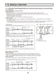
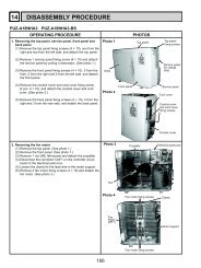
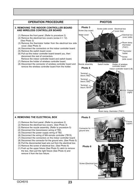
OPERATION PROCEDURE<br />
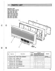
3. REMOVING THE INDOOR CONTROLLER BOARD<br />
AND WIRELESS CONTROLLER BOARD<br />
(1) Remove the front panel. (Refer to procedure 2)<br />
(2) Remove the electrical box covers (screw 4 × 12).<br />
(See Photo 3)<br />
(3) Remove the thermistor holder from the electrical box side<br />
cover. (See Photo 3)<br />
(4) Disconnect the connectors on the indoor controller board.<br />
(5) Remove the switch board cover.<br />
(6) Pull out the indoor controller board toward you, then<br />
disconnect the rest of connectors.<br />
Remove the indoor controller board and switch board.<br />
(7) Remove the holder of wireless controller board.<br />
(8) Disconnect the connector of wireless controller board and<br />
remove the wireless controller board from the holder.<br />
4. REMOVING THE ELECTRICAL BOX<br />
(1) Remove the front panel. (Refer to procedure 2)<br />
(2) Remove the electrical box covers. (See Photo 3)<br />
(3) Remove the nozzle assembly. (Refer to procedure 5)<br />
(4) Disconnect the transmission wiring of TB5.<br />
(5) Disconnect the power supply wiring of TB2.<br />
(6) Disconnect the wiring of MA-remote controller (TB15).<br />
(7) Disconnect the connectors on the indoor controller board.<br />
(8) Disconnect the connector for the ground wire. (See Photo 5)<br />
(9) Pull the disconnected lead wire out from the electrical box.<br />
(10) Remove the screw of electrical box. (See Photo 6)<br />
(11) Push up the upper fixture (See Photo 5) catch to remove<br />
the box, then pull the right fixture (See Photo 4) and<br />
remove it from the box fixture.<br />
OCH515<br />
23<br />
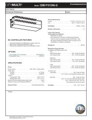
Photo 3<br />
Screw (top cover)<br />
Water cover<br />
Nozzle assembly<br />
Photo 4<br />
Terminal<br />
block (TB2)<br />
Terminal<br />
block (TB5)<br />
Terminal<br />
block (TB15)<br />
Photo 5<br />
Connector for<br />
ground wire<br />
Photo 6<br />
Screw (Electrical box)<br />
PHOTOS<br />
Screw (side cover)<br />
Switch holder Holder of wireless<br />
controller board<br />
Indoor controller board (I.B)<br />
Fixture<br />
(right)<br />
Electrical box<br />
cover (top)<br />
Room temp. thermistor (TH21)<br />
Electrical box<br />
cover (side)<br />
Room temp.<br />
thermistor<br />
(TH21)<br />
Thermistor<br />
holder<br />
Screw<br />
(side cover)<br />
Fixture<br />
(right)<br />
Fixture<br />
(upper)