Service Manual - MyLinkDrive
Service Manual - MyLinkDrive
Service Manual - MyLinkDrive

You also want an ePaper? Increase the reach of your titles
YUMPU automatically turns print PDFs into web optimized ePapers that Google loves.
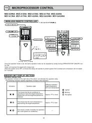
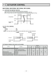
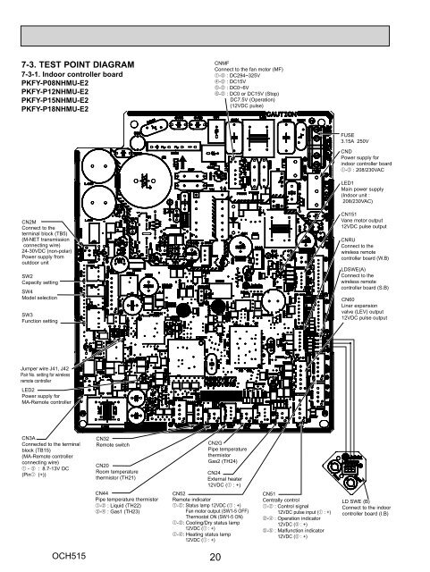
7-3. TEST POINT DIAGRAM<br />
7-3-1. Indoor controller board<br />
PKFY-P08NHMU-E2<br />
PKFY-P12NHMU-E2<br />
PKFY-P15NHMU-E2<br />
PKFY-P18NHMU-E2<br />
CN2M<br />
Connect to the<br />
terminal block (TB5)<br />
(M-NET transmission<br />
connecting wire)<br />
24-30VDC (non-polar)<br />
Power supply from<br />
outdoor unit<br />
SW2<br />
Capacity setting<br />
SW4<br />
Model selection<br />
SW3<br />
Function setting<br />
Jumper wire J41, J42<br />
Pair No. setting for wireless<br />
remote controller<br />
LED2<br />
Power supply for<br />
MA-Remote controller<br />
CN3A<br />
Connected to the terminal<br />
block (TB15)<br />
(MA-Remote controller<br />
connecting wire)<br />
1 - 3 : 8.7-13V DC<br />
(Pin1 (+))<br />
OCH515<br />
CN32<br />
Remote switch<br />
CN20<br />
Room temperature<br />
thermistor (TH21)<br />
CN44<br />
Pipe temperature thermistor<br />
1-2 : Liquid (TH22)<br />
3-4 : Gas1 (TH23)<br />
CNMF<br />
Connect to the fan motor (MF)<br />
1-3 : DC294~325V<br />
4-3 : DC15V<br />
5-3 : DC0~6V<br />
6-3 : DC0 or DC15V (Stop)<br />
DC7.5V (Operation)<br />
(12VDC pulse)<br />
CN2G<br />
Pipe temperature<br />
thermistor<br />
Gas2 (TH24)<br />
CN24<br />
External heater<br />
12VDC (1 : +)<br />
CN52<br />
Remote indicator<br />
1-2: Status lamp 12VDC (1 : +)<br />
Fan motor output (SW1-5 OFF)<br />
Thermostat ON (SW1-5 ON)<br />
1-3: Cooling/Dry status lamp<br />
12VDC (1 : +)<br />
1-4: Heating status lamp<br />
12VDC (1 : +)<br />
20<br />
CN51<br />
Centrally control<br />
1-2 : Control signal<br />
12VDC pulse input (1 : +)<br />
3-4 : Operation indicator<br />
12VDC (3 : +)<br />
3-5 : Malfunction indicator<br />
12VDC (3 : +)<br />
FUSE<br />
3.15A 250V<br />
CND<br />
Power supply for<br />
indoor controller board<br />
1-3 : 208/230VAC<br />
LED1<br />
Main power supply<br />
(Indoor unit :<br />
208/230VAC)<br />
CN151<br />
Vane motor output<br />
12VDC pulse output<br />
CNRU<br />
Connect to the<br />
wireless remote<br />
controller board (W.B)<br />
LDSWE(A)<br />
Connect to the<br />
wireless remote<br />
controller board (S.B)<br />
CN60<br />
Liner expansion<br />
valve (LEV) output<br />
12VDC pulse output<br />
LD SWE (B)<br />
Connect to the indoor<br />
controller board (I.B)