19 - Design of Timber Floor Joists.pdf
19 - Design of Timber Floor Joists.pdf
19 - Design of Timber Floor Joists.pdf

Create successful ePaper yourself
Turn your PDF publications into a flip-book with our unique Google optimized e-Paper software.
36<br />
<strong>Design</strong> principles<br />
TheStructuralEngineer<br />
November 2012<br />
<strong>Timber</strong> is a natural material and is variable<br />
both in strength and stiffness. The strength<br />
and stiffness <strong>of</strong> a piece <strong>of</strong> timber depends<br />
on its species, where it was grown, the<br />
rate <strong>of</strong> growth, the number <strong>of</strong> ‘defects’<br />
(e.g. knots) and the angle <strong>of</strong> the grain. In<br />
order to make effective structural use <strong>of</strong><br />
timber it needs to be graded and allocated<br />
directly or indirectly to a strength class. The<br />
strength <strong>of</strong> a piece <strong>of</strong> timber also depends<br />
on its moisture content and structural<br />
timber should be installed when its moisture<br />
content is similar to that experienced during<br />
growth. Allowances have to be made for<br />
this moisture content when the structure is<br />
designed.<br />
It should be noted that this Technical<br />
Guidance Note is solely concerned with<br />
the design <strong>of</strong> solid timber floor joists and<br />
not other forms <strong>of</strong> compound timber floor<br />
joists available. This includes Glulam and<br />
›<br />
Note 18 Level 1<br />
Technical<br />
Technical Guidance Note<br />
<strong>Design</strong> <strong>of</strong> timber floor joists<br />
Introduction<br />
One <strong>of</strong> the most common structural elements is the timber floor joist. This<br />
is normally found in residential properties, but can also be seen in medium<br />
sized commercial developments. This Technical Guidance Note will explain<br />
the principles behind the design <strong>of</strong> timber floor joists and provide a worked<br />
example. All <strong>of</strong> the advice given will be in accordance with BS EN <strong>19</strong>95-1-1<br />
Eurocode 5: <strong>Design</strong> <strong>of</strong> <strong>Timber</strong> Structures – Part 1-1: General – Common<br />
rules and rules for buildings.<br />
Laminated Veneer Lumber (LVL) joists as<br />
they are beyond the scope <strong>of</strong> this note.<br />
<strong>Timber</strong> floor joist strength<br />
grades and classes<br />
S<strong>of</strong>twood timber can be visually graded<br />
to General Structural (GS) and Special<br />
Structural (SS) grades. These grades are<br />
then allocated to a particular Strength<br />
Class. With respect to timber floor joists,<br />
in the UK they are typically sawn from GS<br />
and SS s<strong>of</strong>twoods and are graded in two<br />
strength classes respectively: C16 and C24.<br />
C16 is the more common grade but weaker<br />
class and is therefore easier and cheaper<br />
to procure. C24 is a little stronger, but more<br />
expensive and is generally used where<br />
restrictions such as geometry and depth <strong>of</strong><br />
floor construction play a significant part in<br />
the design <strong>of</strong> the structure. An example <strong>of</strong><br />
such an instance would be joists that have<br />
long spans or a trimming beam around a<br />
large void.<br />
The material properties <strong>of</strong> C16 and C24<br />
timber are given in Table 1.<br />
Table 1: Material properties <strong>of</strong> s<strong>of</strong>twood timber grades C16 and C24<br />
Properties C16 C24<br />
Characteristic bending strength (N/mm 2 ) – f m,k 16 24<br />
Characteristic shear strength (N/mm 2 ) – f v,k 3.2 4.0<br />
Parallel mean modulus <strong>of</strong> elasticity (N/mm 2 ) – E 0,mean 8000 11000<br />
Mean density (kg/m 3 ) 370 420<br />
ICON<br />
LEGEND<br />
• <strong>Design</strong> principles<br />
• Applied practice<br />
• Worked example<br />
• Further reading<br />
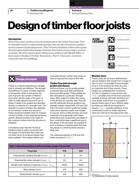
Member sizes<br />
<strong>Timber</strong> joists are cut to pre-defined sizes<br />
and are limited in their length from a range <strong>of</strong><br />
1.8m to 5.4m. It is possible to have lengths<br />
<strong>of</strong> up to 7.2m however, but they do come<br />
at a premium due to their paucity. These<br />
lengths are subdivided into increments<br />
<strong>of</strong> 0.3m. In regards to cross-section size,<br />
Table 2 provides a list <strong>of</strong> the most commonly<br />
available sections, with both machined and<br />
sawn timber sizes shown. It is possible to<br />
specify timber sizes <strong>of</strong> up to 300mm deep,<br />
but these are difficult and expensive to<br />
acquire. Figure 1 provides guidance on the<br />
nomenclature used for timber elements,<br />
which are referred to throughout this note.<br />
Characteristic density (kg/m3 ) 310 350 Figure 1 • Nomenclature for timber elements
Table 2: Common sizes <strong>of</strong> timber floor joists<br />
Sawn depth<br />
(h) mm<br />
Sawn width<br />
(b) mm<br />
Exposure conditions<br />
<strong>Timber</strong> is a hygroscopic material that<br />
absorbs/releases moisture from/to its<br />
surrounding environment depending on the<br />
amount <strong>of</strong> moisture in that environment. As<br />
the strength and stiffness properties are<br />
dependent on the moisture content, it is<br />
necessary to account for the environment<br />
around the timber. Three service classes<br />
have been defined. Examples <strong>of</strong> typical<br />
environments and the respective service<br />
class are:<br />
• Service class 1 – intermediate floors, warm<br />
ro<strong>of</strong>s, internal and party timber frame walls<br />
• Service class 2 – ground floors, cold ro<strong>of</strong>s,<br />
timber frame walls that are against the outer<br />
skin <strong>of</strong> cladding and all other instances<br />
where the timber is protected from direct<br />
exposure to water<br />
• Service class 3 – external, fully exposed<br />
Load duration<br />
The strength <strong>of</strong> a piece <strong>of</strong> timber is<br />
dependent <strong>of</strong> the duration <strong>of</strong> the load. The<br />
longer the duration <strong>of</strong> the load the higher the<br />
strength <strong>of</strong> timber that must be provided in<br />
order to resist that load. To this end there<br />
are a number <strong>of</strong> factors that are applied to<br />
the characteristic properties <strong>of</strong> the timber<br />
as defined in Table 1. The UK National Annex<br />
to Eurocode BS EN <strong>19</strong>95-1-1 classifies load<br />
durations as follows:<br />
• Permanent – more than 10 years, e.g. selfweight<br />
including finishes<br />
• Long term – 6 months to 10 years e.g.<br />
storage loading<br />
• Medium term – 1 week to 6 months e.g.<br />
imposed floor loads<br />
Machined depth<br />
(h) mm<br />
Machined width<br />
(b) mm<br />
150 25 145 22<br />
175 38 170 35<br />
200 47 <strong>19</strong>5 44<br />
225 63 220 60<br />
250 75 245 72<br />
Table 3: Values <strong>of</strong> k mod for solid timber joists<br />
• Short term – less than 1 week e.g.<br />
snow loads, maintenance access and<br />
accidental loads<br />
• Instantaneous – fractions <strong>of</strong> a second e.g.<br />
wind, impact and explosive loads<br />
The figures given in Table 3 provide the<br />
values for the factor k mod , which is the factor<br />
that is applied to the strength properties <strong>of</strong><br />
timber and is based on the imposed load<br />
(variable action) duration. Note that in the<br />
case <strong>of</strong> load combinations the load condition<br />
with the shortest time period defines the<br />
value <strong>of</strong> k mod . When designing timber<br />
elements it is important to check for all<br />
conditions and to design the element based<br />
on the most critical. These conditions along<br />
with their respective k mod values are:<br />
• Permanent loads with k mod = 0.6<br />
• Permanent loads + long term loads<br />
with k mod = 0.7<br />
• Permanent loads + long term loads +<br />
medium term loads with k mod = 0.8<br />
• Permanent loads + long term loads +<br />
medium term loads + short term loads<br />
with k mod = 0.9<br />
• Permanent loads + long term loads +<br />
medium term loads + short term loads +<br />
instantaneous loads with k mod = 1<br />
For timber floor joists within a building the<br />
typical critical condition is the imposed<br />
floor load with the self-weight <strong>of</strong> the joists<br />
and super-imposed dead load. This load<br />
condition results in a value <strong>of</strong> k mod <strong>of</strong> 0.8<br />
as it is subject to an imposed load, which<br />
is defined as medium term, as well as<br />
self-weight.<br />
Service class Permanent Long term Medium term Short term Instantaneous<br />
1 & 2 0.6 0.7 0.8 0.9 1.10<br />
3 0.5 0.55 0.65 0.7 0.9<br />
www.thestructuralengineer.org<br />
37<br />
Deformation<br />
The elastic properties <strong>of</strong> a timber structure<br />
depend on the moisture content <strong>of</strong> the<br />
timber and consequently the deflection<br />
will be dependent on the service class.<br />
To take this into account the factor k def is<br />
applied to the elastic modulus properties<br />
<strong>of</strong> the timber. Table 4 defines these values.<br />
Table 4: Values <strong>of</strong> k def for solid timber joists<br />
Service<br />
class<br />
Enhancement due to shallow<br />
member size<br />
The way that the grading rules for structural<br />
timber work, means that for joists less than<br />
150mm in depth, some enhancement <strong>of</strong> the<br />
strength is allowed.<br />
To reflect this, a modification factor k h is<br />
applied to bending strength <strong>of</strong> the timber. If a<br />
member is less than or equal to 150mm deep<br />
and has a material density <strong>of</strong> less than 700<br />
kg/m 3 , then k h factor is defined thus:<br />
150 . 02<br />
kh<br />
= a k<br />
h<br />
1 2 3<br />
k def 0.6 0.8 2.00<br />
or 1.3 whichever is the lesser.<br />
For all members that are greater than<br />
150mm deep, the value <strong>of</strong> k h is taken to<br />
be 1.0.<br />
(1)<br />
Load sharing<br />
<strong>Timber</strong> floor joists are generally placed at<br />
fairly close centres with decking/boarding<br />
across them which will distribute load<br />
between the joists. To account for this,<br />
the modification factor ksys is applied to<br />
characteristic strength properties <strong>of</strong> the<br />
timber joist which enhances its resistance to<br />
bending and shear stress. Provided the floor<br />
boards/boarding has staggered connections<br />
and are continuous over at least two spans,<br />
the value <strong>of</strong> ksys is taken to be 1.1. In all other<br />
instances the value <strong>of</strong> ksys is taken to be 1.0.<br />
Lateral torsional buckling <strong>of</strong><br />
timber joists<br />
In most instances the risk <strong>of</strong> lateral torsional<br />
buckling affecting a floor joist is not present.<br />
This is due to the existence <strong>of</strong> a floor<br />
finish that the joists are supporting acting<br />
as a restraint. In the rare condition where<br />
the compression face <strong>of</strong> floor joists is not<br />
restrained against bending induced torsional<br />
rotation, then the factor k crit is applied to<br />
the bending capacity <strong>of</strong> the joist. For more
38<br />
TheStructuralEngineer<br />
November 2012<br />
information on this, the reader is directed<br />
to clause 6.3.3 <strong>of</strong> BS EN <strong>19</strong>95-1-1, which<br />
describes the derivation <strong>of</strong> k crit .<br />
Applied bending stress<br />
The applied bending stress to floor joists<br />
is associated to its major axis, which is<br />
described as ‘y-y’ in Figure 1. To determine<br />
the design bending stress, the design<br />
bending moment is calculated based on<br />
the applied loads and support conditions<br />
<strong>of</strong> the joist as well as its geometry. The<br />
equation for determining the design<br />
bending stress (σm,y,d ) to a timber joist<br />
is as follows:<br />
My,d<br />
vm,y,d =<br />
(2)<br />
Wy<br />
Where:<br />
My,d is the design bending moment<br />
is the elastic modulus <strong>of</strong> the joist, defined as:<br />
Wy<br />
Wy<br />
=<br />
bh<br />
2<br />
6<br />
Applied shear stress<br />
For a simply supported joist the design<br />
maximum shear force is equal to the design<br />
reaction. In the case <strong>of</strong> timber the maximum<br />
design shear stress (not average shear<br />
stress) needs to be checked against the<br />
design shear resistance. The maximum<br />
design shear stress <strong>of</strong> a rectangular section<br />
is calculated using:<br />
3Vd<br />
xd<br />
=<br />
2bh<br />
Where:<br />
Vd is the design applied shear force<br />
h is the depth <strong>of</strong> section under consideration<br />
at the point <strong>of</strong> support<br />
b is the width <strong>of</strong> the section under<br />
consideration<br />
If the beam is notched on the same side as<br />
the support, the design shear resistance<br />
can be considerably reduced and is a detail<br />
which should be avoided if possible.<br />
(3)<br />
(4)<br />
Partial factor due to material variances<br />
Like all materials used as structural<br />
elements, timber has a partial factor, which<br />
is applied to its strength properties due to<br />
variances within it. In the case <strong>of</strong> solid timber<br />
elements, the partial factor has a value <strong>of</strong> 1.3.<br />
Bending strength and shear strength<br />
Once the applied forces and subsequent<br />
stresses are determined, the design bending<br />
and shear strengths <strong>of</strong> the timber joist<br />
need to be calculated. These are compared<br />
against the applied design stresses in order<br />
to determine the acceptability <strong>of</strong> the chosen<br />
joist size and strength grade.<br />
›<br />
Note 18 Level 1<br />
Technical<br />
Technical Guidance Note<br />
<strong>Design</strong> bending strength is defined as:<br />
kh $ kcrit $ kmod $ ksys $ fm,k<br />
fm,y,d<br />
=<br />
(5)<br />
c M<br />
<strong>Design</strong> shear strength is defined as:<br />
kmod $ ksys $ fv,k<br />
fv,d<br />
=<br />
(6)<br />
c M<br />
The value <strong>of</strong> fv,d is then multiplied against the<br />
effective depth and width <strong>of</strong> the timber floor<br />
joist at the point <strong>of</strong> support. This is compared<br />
against the applied design shear the timber<br />
joist has to support. In order to take into<br />
account cracking within the timber, the width<br />
<strong>of</strong> the joist is reduced via factor kcr which for<br />
solid timber members is taken as 0.67.<br />
Worked example<br />
Serviceability<br />
The deflections <strong>of</strong> timber joists should be<br />
limited so that any brittle finishes they’re<br />
supporting are not damaged. Table 5<br />
provides guidance on the vertical deflection<br />
limits for joists that are based on the<br />
characteristic imposed loads (variable<br />
actions) and dead loads (permanent<br />
actions) that are being applied to the<br />
floor joists.<br />
Creep must also be considered for timber<br />
elements as it is a significant factor when<br />
assessing serviceability limits. To allow for<br />
this, the instantaneous deflection due to the<br />
permanent loads is increased by a factor<br />
A timber floor is to span 4.8m and is supporting a characteristic imposed floor load <strong>of</strong><br />
2.5kN/m 2 . The joists are placed at 400mm spacing and have timber boards fixed on top<br />
that have a self-weight <strong>of</strong> 0.15kN/m 2 . The presence <strong>of</strong> these boards provides full lateral<br />
restraint to the timber floor joists as well as allowing for load sharing between floor joists.<br />
The finish to the floor is brittle. Check to see if a 250mm x 75mm C16 timber joist can<br />
support this load.
Table 5: Deflection limits for<br />
solid timber joists<br />
Use Deflection limit<br />
Brittle finishes<br />
e.g. plasterboard,<br />
ceilings, walls<br />
No brittle finishes<br />
e.g. ro<strong>of</strong>s<br />
Accidental<br />
e.g. during a fire<br />
Span/250<br />
Span/150<br />
Span/20<br />
(1+k def ). The instantaneous deflection<br />
for imposed (variable) load is increased by<br />
a factor (1+ψ 2,1k def ), assuming only one<br />
variable load. The sum <strong>of</strong> these deflections,<br />
less any precamber, provides the overall<br />
deflection due to bending.<br />
There is also the issue <strong>of</strong> deflection due to<br />
shear. This is rarely a critical condition, but it<br />
is prudent to add 10% to the overall deflection<br />
to arrive at a final value to allow for it.<br />
Additionally floor joists should be checked<br />
to ensure that their vibration performance is<br />
acceptable, this can be <strong>of</strong> concern with joists<br />
which span is in excess <strong>of</strong> 4.0m.<br />
www.thestructuralengineer.org<br />
Eurocode 0.<br />
Applied practice<br />
BS EN <strong>19</strong>95-1-1 Eurocode 5: <strong>Design</strong> <strong>of</strong><br />
<strong>Timber</strong> Structures – Part 1-1: General –<br />
Common rules and rules for buildings<br />
39<br />
<strong>Timber</strong> joist span tables<br />
It is possible to refer to timber joist span<br />
tables for sizing <strong>of</strong> joists, such as those<br />
included in Table 7 <strong>of</strong> BS 8103:3 2009. These<br />
tables however are limited to imposed loads<br />
<strong>of</strong> 1.5 kN/m 2 .<br />
Alternatively it is possible to use the<br />
Eurocode 5 Span Tables, that have been<br />
developed by TRADA. These have a similar<br />
set <strong>of</strong> tables, but again are limited to imposed<br />
loads <strong>of</strong> no greater than 1.5 kN/m 2 .<br />
BS EN <strong>19</strong>95-1-1 UK National Annex to<br />
Eurocode 5: <strong>Design</strong> <strong>of</strong> <strong>Timber</strong> Structures –<br />
Part 1-1: General – Common rules and rules<br />
for buildings<br />
BS EN 336 2009: Structural <strong>Timber</strong> –<br />
Sizes, permitted deviations<br />
BS EN 338 2009: Structural <strong>Timber</strong> –<br />
Strength classes<br />
BS 8103:3 2009: Structural <strong>Design</strong> <strong>of</strong> Lowrise<br />
Buildings Part 3: Code <strong>of</strong> practice for<br />
timber floors and ro<strong>of</strong>s for housing<br />
Glossary and<br />
further reading<br />
Hygroscopic – Moisture absorbing.<br />
Modification factors – Factors that<br />
are applied to the characteristic material<br />
properties <strong>of</strong> timber elements.<br />
Precamber – A forced deformation <strong>of</strong> a<br />
member that reduces the effect <strong>of</strong> deflection<br />
following the application <strong>of</strong> loads.<br />
Further Reading<br />
The Institution <strong>of</strong> Structural Engineers/<br />
TRADA (2010) Manual for the design <strong>of</strong><br />
timber building structures to Eurocode<br />
5 London: The Institution <strong>of</strong> Structural<br />
Engineers/TRADA<br />
TRADA (2009) Eurocode 5 span tables<br />
for solid timber members (3rd ed.) High<br />
Wycombe: TRADA<br />
Porteous, J. and Kermani, A. (2007)<br />
Structural <strong>Timber</strong> <strong>Design</strong> to Eurocode 5<br />
Chichester: John Wiley & Sons