CARLETON UNIVERSITY Laboratory 2.0 - Department of ...
CARLETON UNIVERSITY Laboratory 2.0 - Department of ...
CARLETON UNIVERSITY Laboratory 2.0 - Department of ...

Create successful ePaper yourself
Turn your PDF publications into a flip-book with our unique Google optimized e-Paper software.
Carleton University<br />
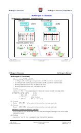
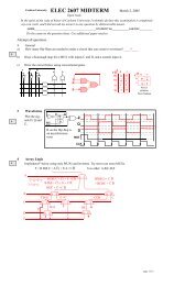
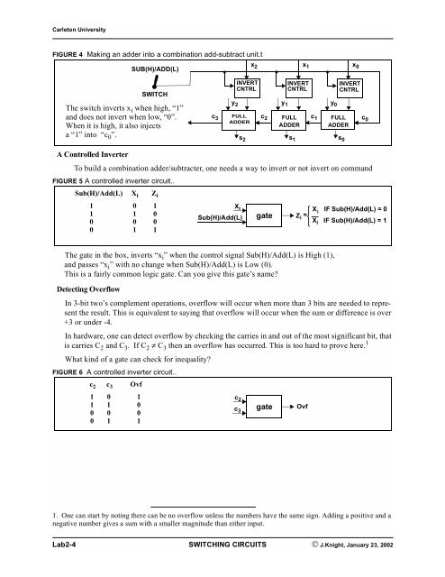
FIGURE 4 Making an adder into a combination add-subtract unit.t<br />
The gate in the box, inverts “x i” when the control signal Sub(H)/Add(L) is High (1),<br />
and passes “x i” with no change when Sub(H)/Add(L) is Low (0).<br />
This is a fairly common logic gate. Can you give this gate’s name?<br />
Detecting Overflow<br />
SUB(H)/ADD(L)<br />
SWITCH<br />
The switch inverts x i when high, “1”<br />
and does not invert when low, “0”.<br />
When it is high, it also injects<br />
a “1” into “c 0”.<br />
In 3-bit two’s complement operations, overflow will occur when more than 3 bits are needed to represent<br />
the result. This is equivalent to saying that overflow will occur when the sum or difference is over<br />
+3 or under -4.<br />
In hardware, one can detect overflow by checking the carries in and out <strong>of</strong> the most significant bit, that<br />
is carries C2 and C3 . IfC2 ≠ C3 then an overflow has occurred. This is too hard to prove here. 1<br />
What kind <strong>of</strong> a gate can check for inequality?<br />
FIGURE 6 A controlled inverter circuit..<br />
c 3<br />
1. One can start by noting there can be no overflow unless the numbers have the same sign. Adding a positive and a<br />
negative number gives a sum with a smaller magnitude than either input.<br />
Lab2-4 SWITCHING CIRCUITS © J.Knight, January 23, 2002<br />
y 2<br />
FULL<br />
ADDER<br />
s 2<br />
x 2<br />
INVERT<br />
CNTRL<br />
c 2<br />
y 1<br />
FULL<br />
ADDER<br />
s 1<br />
x 1<br />
INVERT<br />
CNTRL<br />
c 1<br />
y 0<br />
FULL<br />
ADDER<br />
s 0<br />
x 0<br />
INVERT<br />
CNTRL<br />
A Controlled Inverter<br />
To build a combination adder/subtracter, one needs a way to invert or not invert on command<br />
FIGURE 5 A controlled inverter circuit..<br />
Sub(H)/Add(L) Xi Zi 1 0 1<br />
1 1 0<br />
0 0 0<br />
0 1 1<br />
c2 c3 Ovf<br />
1 0 1<br />
1 1 0<br />
0 0 0<br />
0 1 1<br />
X i<br />
Sub(H)/Add(L) gate Z i = X i IF Sub(H)/Add(L) = 0<br />
X i IF Sub(H)/Add(L) = 1<br />
c 2<br />
c 3<br />
gate<br />
Ovf<br />
c 0