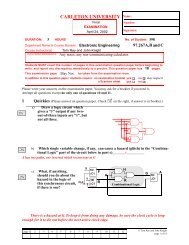
CARLETON UNIVERSITY Laboratory 2.0 - Department of ...
CARLETON UNIVERSITY Laboratory 2.0 - Department of ...
CARLETON UNIVERSITY Laboratory 2.0 - Department of ...

Create successful ePaper yourself
Turn your PDF publications into a flip-book with our unique Google optimized e-Paper software.
<strong>CARLETON</strong> <strong>UNIVERSITY</strong><br />
<strong>Department</strong> <strong>of</strong> Electronics<br />
97.267 Switching Circuits January 23, 2002<br />
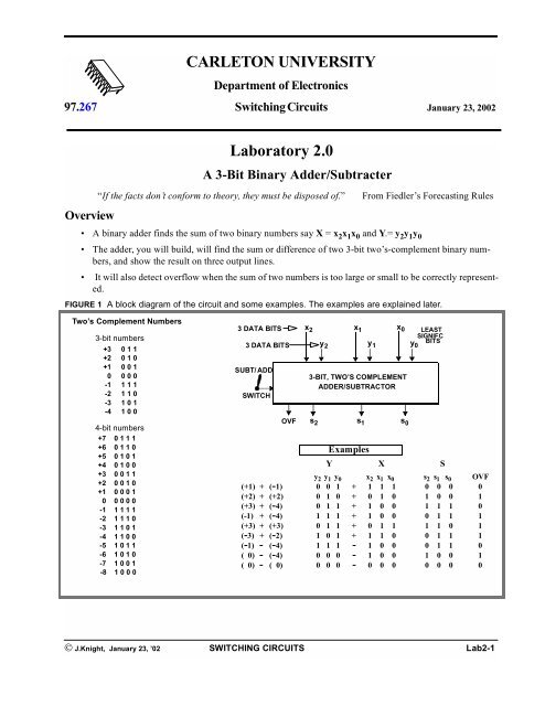
Overview<br />
<strong>Laboratory</strong> <strong>2.0</strong><br />
A 3-Bit Binary Adder/Subtracter<br />
“If the facts don’t conform to theory, they must be disposed <strong>of</strong>.” From Fiedler’s Forecasting Rules<br />
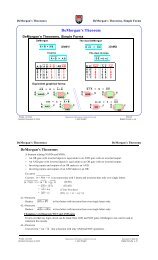
A binary adder finds the sum <strong>of</strong> two binary numbers say X = x2x1x0 and Y.= y2y1y0 The adder, you will build, will find the sum or difference <strong>of</strong> two 3-bit two’s-complement binary numbers,<br />
and show the result on three output lines.<br />
It will also detect overflow when the sum <strong>of</strong> two numbers is too large or small to be correctly represented.<br />
FIGURE 1 A block diagram <strong>of</strong> the circuit and some examples. The examples are explained later.<br />
Two’s Complement Numbers<br />
3-bit numbers<br />
+3 011<br />
+2 010<br />
+1 001<br />
0 000<br />
-1 111<br />
-2 110<br />
-3 101<br />
-4 100<br />
4-bit numbers<br />
+7 0111<br />
+6 0110<br />
+5 0101<br />
+4 0100<br />
+3 0011<br />
+2 0010<br />
+1 0001<br />
0 0 0 0 0<br />
-1 1111<br />
-2 1110<br />
-3 1101<br />
-4 1100<br />
-5 1011<br />
-6 1010<br />
-7 1001<br />
-8 1000<br />
3 DATA BITS x2 x1 x0 LEAST<br />
SIGNIFC<br />
y<br />
BITS<br />
3 DATA BITS<br />
2<br />
y1 y0 SUBT/ ADD<br />
SWITCH<br />
3-BIT, TWO’S COMPLEMENT<br />
ADDER/SUBTRACTOR<br />
© J.Knight, January 23, ’02 SWITCHING CIRCUITS Lab2-1<br />
OVF<br />
s 2<br />
s 1<br />
Examples<br />
Y X S<br />
y 2 y 1 y 0 x 2 x 1 x 0 s 2 s 1 s 0 OVF<br />
(+1) + (-1) 0 0 1 + 1 1 1 0 0 0 0<br />
(+2) + (+2) 0 1 0 + 0 1 0 1 0 0 1<br />
(+3) + (-4) 0 1 1 + 1 0 0 1 1 1 0<br />
(-1) + (-4) 1 1 1 + 1 0 0 0 1 1 1<br />
(+3) + (+3) 0 1 1 + 0 1 1 1 1 0 1<br />
(-3) + (-2) 1 0 1 + 1 1 0 0 1 1 1<br />
(-1) - (-4) 1 1 1 - 1 0 0 0 1 1 0<br />
( 0)- (-4) 0 0 0 - 1 0 0 1 0 0 1<br />
( 0)- ( 0) 0 0 0 - 0 0 0 0 0 0 0<br />
s 0
Carleton University<br />
Background<br />
Two’s Complement Numbers<br />
3-bit<br />
two’s complement<br />
numbers<br />
These are a method <strong>of</strong> representing negative numbers.<br />
+3 011<br />
It is used because both positive and negative numbers can be added on the same<br />
hardware, and because a few gates will convert an adder into a subtractor.<br />
+2<br />
+1<br />
0<br />
010<br />
001<br />
000<br />
Negative numbers all start with “1”. The most significant bit is “1”.).<br />
-1<br />
-2<br />
111<br />
110<br />
There is one more negative number than positive number.<br />
Two’s complement numbers look just like positive binary integers, and one<br />
-3<br />
-4<br />
101<br />
100<br />
adds them the same way. They are two’s compliment only in the way you interpret them.<br />
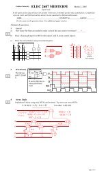
Addition Of Binary Numbers, Including Two’s Complement Numbers<br />
FIGURE 2 Two’s complement binary addition example<br />
+<br />
(+3) 0 1 1<br />
1 1 0 Carry<br />
(- 2) 1 1 0<br />
0 1 1 + 1 1 0<br />
Normal binary adds use the <strong>of</strong>f-end carry.<br />
With 2’s complement numbers, ignore it<br />
(+1)<br />
To add two two’s complement numbers, add them bit-by-bit being sure to transfer the carries<br />
over to the next column. In normal binary adds, the <strong>of</strong>f-end carry is part <strong>of</strong> the number. Thus if two<br />
three-bit numbers are added, the result may be a four-bit number. This is shown in the little box on<br />
the right <strong>of</strong> Fig. 2 (p. 2).<br />
With two’s complement numbers the final <strong>of</strong>f-end carry is ignored so the result <strong>of</strong> adding two<br />
3-bit numbers is always a 3-bit number. All the adds in this lab will be two’s complement adds.<br />
Notice the adder gives the same result in both cases. If we say it is a two’s complement addition<br />
we ignore the <strong>of</strong>f-end carry. If the rest <strong>of</strong> the number starts with a “0” we read it like any positive<br />
binary number. If leading bit <strong>of</strong> the rest <strong>of</strong> the number is “0”, look it up in the tanle, or read the<br />
next section.<br />
If one does the same addition on the same hardware, but says that the bits represent positive integers,<br />
one gets the result shown in the box in Fig. 2 (p. 2). One looks at the <strong>of</strong>f-end carry and one<br />
reads the answer as a positive number. We will not use this type <strong>of</strong> addition in this lab.<br />
To Take The Two’s Complement Of A Binary Number<br />
1. Invert each bit.<br />
2. add 1<br />
3. ignore any carry.<br />
Example: Take the 2’s complement <strong>of</strong> +1 (001 in binary).<br />
Take 001, invert bits110<br />
add one 1<br />
111 (111 is ‘-1’ in 2’s complement)<br />
Find the 3-bit two’s complement <strong>of</strong> +3, -2, -1, -4. using the method above. (You will be asked to do<br />
this in the prelab.)<br />
Lab2-2 SWITCHING CIRCUITS © J.Knight, January 23, 2002<br />
1<br />
0<br />
0<br />
1<br />
+ (+3)<br />
(+6)<br />
1<br />
0 1 1<br />
1 1 0<br />
(+9) 1 0 0 1<br />
Regular binary addition<br />
Not 2’s complement<br />
1<br />
0
What is special about the 3-bit two’s complement <strong>of</strong> -4?<br />
The Half Adder, an Adder for Two Single-Bit Numbers<br />
This circuit can add 0+0, 0+1, 1+0, and 1+1. It gives a single-bit sum<br />
output s i and a single-bit carry output c i+1<br />
The Full-Adder, an Adder for Three Single-Bit Numbers<br />
The half-adder is not enough for adding binary numbers. One must be able<br />
to add three input bits. The third bit, “c i” will turn out to be a carry input.<br />
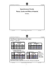
An Iterative Adder Circuit for Multibit Numbers<br />
One can make a multibit adder by combining full adders in an iterative circuit.<br />
Iterative circuits are also called bit-sliced circuits<br />
FIGURE 3 A 3-bit adder made from three full adders..<br />
Not part <strong>of</strong> sum with 2’s<br />
complement numbers<br />
The carry output <strong>of</strong> one full-adder is sent to the next full-adder. In the above picture, “c 3 ” is ignored<br />
in two’s complement addition. “c 0 ” is always zero since their is no carry input<br />
Adding Multibit Two’s Complement Numbers<br />
The advantage <strong>of</strong> two’s complement numbers is that negative numbers, are added exactly the same<br />
way positive numbers. Thus the positive integer adder circuit in Fig. 3 (p. 3) could be used for adding<br />
two’s complement integers.<br />
However, unlike 3-bit positive integers, you cannot add 3-bit two’s complement integers to get a 4bit<br />
number. The carry out c3, is never part <strong>of</strong> the sum.<br />
A Two’s Complement Subtractor<br />
To calculate Y-X, one adds Y to the 2’s complement <strong>of</strong> X.<br />
~<br />
To get the 2’s compliment, inverts the bits <strong>of</strong> X, to get say X and adds “1”. In summary,<br />
Y - X = Y +<br />
~<br />
X + 1<br />
A convenient way to add the “1”, is to use “c 0”.<br />
A 2’s complement subtracter.<br />
A Combination Adder-Subtractor<br />
One can make a circuit that both adds and subtracts by:<br />
(1) Having the inverters swithe in and out <strong>of</strong> the circuit by external control.<br />
(2) Making the initial carry in, c 0 = 0 for addition and c 0 = 1 for subtraction.<br />
c 3<br />
This carry out will be used<br />
to help detect overflow<br />
y2 x2 FULL<br />
ADDER<br />
c2 © J.Knight,January 23, ’02 SWITCHING CIRCUITS Lab2-3<br />
c 3<br />
s 2<br />
y 2<br />
y1 x1 FULL<br />
ADDER<br />
c1 x 2<br />
FULL<br />
ADDER<br />
s 2<br />
z 2= ~ x 2<br />
c 2<br />
s 1<br />
y 1<br />
s 1<br />
x 1<br />
FULL<br />
ADDER<br />
y 0<br />
c i+1<br />
FULL<br />
ADDER<br />
c 1<br />
s 0<br />
y i<br />
HALF<br />
ADDER<br />
c i+1<br />
y i<br />
s i<br />
FULL<br />
ADDER<br />
x 0<br />
s i<br />
c 0<br />
x i<br />
x i<br />
c i<br />
~ ~ 1<br />
z1= x1 y0 z0= x0 c0 FULL<br />
ADDER<br />
s 0<br />
x 0
Carleton University<br />
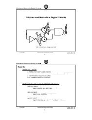
FIGURE 4 Making an adder into a combination add-subtract unit.t<br />
The gate in the box, inverts “x i” when the control signal Sub(H)/Add(L) is High (1),<br />
and passes “x i” with no change when Sub(H)/Add(L) is Low (0).<br />
This is a fairly common logic gate. Can you give this gate’s name?<br />
Detecting Overflow<br />
SUB(H)/ADD(L)<br />
SWITCH<br />
The switch inverts x i when high, “1”<br />
and does not invert when low, “0”.<br />
When it is high, it also injects<br />
a “1” into “c 0”.<br />
In 3-bit two’s complement operations, overflow will occur when more than 3 bits are needed to represent<br />
the result. This is equivalent to saying that overflow will occur when the sum or difference is over<br />
+3 or under -4.<br />
In hardware, one can detect overflow by checking the carries in and out <strong>of</strong> the most significant bit, that<br />
is carries C2 and C3 . IfC2 ≠ C3 then an overflow has occurred. This is too hard to prove here. 1<br />
What kind <strong>of</strong> a gate can check for inequality?<br />
FIGURE 6 A controlled inverter circuit..<br />
c 3<br />
1. One can start by noting there can be no overflow unless the numbers have the same sign. Adding a positive and a<br />
negative number gives a sum with a smaller magnitude than either input.<br />
Lab2-4 SWITCHING CIRCUITS © J.Knight, January 23, 2002<br />
y 2<br />
FULL<br />
ADDER<br />
s 2<br />
x 2<br />
INVERT<br />
CNTRL<br />
c 2<br />
y 1<br />
FULL<br />
ADDER<br />
s 1<br />
x 1<br />
INVERT<br />
CNTRL<br />
c 1<br />
y 0<br />
FULL<br />
ADDER<br />
s 0<br />
x 0<br />
INVERT<br />
CNTRL<br />
A Controlled Inverter<br />
To build a combination adder/subtracter, one needs a way to invert or not invert on command<br />
FIGURE 5 A controlled inverter circuit..<br />
Sub(H)/Add(L) Xi Zi 1 0 1<br />
1 1 0<br />
0 0 0<br />
0 1 1<br />
c2 c3 Ovf<br />
1 0 1<br />
1 1 0<br />
0 0 0<br />
0 1 1<br />
X i<br />
Sub(H)/Add(L) gate Z i = X i IF Sub(H)/Add(L) = 0<br />
X i IF Sub(H)/Add(L) = 1<br />
c 2<br />
c 3<br />
gate<br />
Ovf<br />
c 0
Prelab<br />
(This must be prepared prior to the scheduled lab session. It will be checked near the start <strong>of</strong> the lab. It will<br />
also be an appendix for your final report.)<br />
3.0 Make a table <strong>of</strong> 5-bit two’s-complement numbers showing them opposite their decimal values. You<br />
may put in a row <strong>of</strong> dots “. . .” to save writing, but show the top 3 numbers, the bottom 3 numbers, and<br />
+2, +1, 0, -1 and -2.<br />
3.1 Show how to calculate 3-bit two’s complement <strong>of</strong> numbers by inverting and adding 1. Use +3 , -1 and<br />
-4 as examples. Decide if there is a 3-bit two’s complement <strong>of</strong> -4.<br />
3.2 Do the following (a through d) arithmetic problems as a 3-bit binary adder/subtracter would do them.<br />
Show how the carries propagate and how the overflow is calculated as is illustrated Fig. 7 (p. 5) for<br />
the 4 bit subtraction <strong>of</strong> X - Y = (+5) - (-6).<br />
(a) (+1) + (+2), (b) (+2) + (-2), (c) (-2) + (-3), (d) (+3) - (-3), (e) (-3) - (+3) .<br />
FIGURE 7 Doing a 2’s complement subtract.<br />
3.3 Complete the truth table for a generic full adder.<br />
The three inputs are xi ,yi ,andci .<br />
The two outputs are sum and carry, that is si and ci+1 Partial Truth Table for a Generic Full Adder<br />
y i x i c i c i+1 s i<br />
Not Equal Means Overflow 0 ≠ 1<br />
(+5)<br />
- (-6)<br />
0<br />
1<br />
1<br />
0<br />
0<br />
1<br />
1<br />
0<br />
0<br />
+<br />
1<br />
0<br />
0<br />
0<br />
1<br />
1<br />
1<br />
0<br />
0<br />
Carry<br />
1<br />
1<br />
Subtract here means invert all bits here<br />
Then the subtraction can be done as addition<br />
(-5) 1 0 1<br />
1<br />
1<br />
Initial 1 carry in, as part <strong>of</strong><br />
2’s complement calculation<br />
Provided an extra 1 is added to the least significant bit.<br />
Expression for<br />
c i+1<br />
1 1 1 1 1 yixici yixici 3.4 Obtain the equations for the generic full adder from the truth table.<br />
3.5 Simplify the equations.<br />
Hint 1: (This may or may not help you)<br />
(a⊕b)c + ab = ac +bc+ab<br />
Expression for<br />
s i<br />
0 0 0 0 0<br />
0 0 1 0 1 y i x i c i<br />
0 1 0 0 1 y ix ic i<br />
0 1 1 1 0 y i x i c i<br />
1 0 1 1 0 y i x i c i<br />
-- -- -- -- -- ---- ----<br />
The formula is proven below using Karnaugh maps. If you have not yet taken these maps you will<br />
have to take it on faith for another week or so.<br />
© J.Knight,January 23, ’02 SWITCHING CIRCUITS Lab2-5<br />
c i+1<br />
y i<br />
FULL<br />
ADDER<br />
s i<br />
x i<br />
c i
Carleton University<br />
FIGURE 8 The formula, proven below by Karnaugh maps, can slightly simplify the carry output.<br />
ab<br />
c<br />
00 01 11 10<br />
c<br />
00 01 11 10<br />
0<br />
0<br />
1 1 1<br />
1 1<br />
1 1<br />
3.6 Take the simplified equations for the full-adder subcircuit you just derived<br />
a) Draw a schematic from the minimal equations you derived.<br />
3.7 What logic gate can function as a controlled inverter?<br />
What gate can test two bits for equality?<br />
3.8 Design a generic “invert control” unit that inverts the” x i” input when subtract is selected.<br />
3.9 Design the circuit that detects overflow.<br />
3.10 Draw a block diagram for the complete 3-bit adder/subtracter. Use blocks for the standard subcircuits<br />
you designed in subsections 3.6 , 3.8 and 3.9 . The figure below gives an idea <strong>of</strong> what is wanted,.<br />
However several necessary things are left out.<br />
FIGURE 9 Partial block diagram <strong>of</strong> the adder/subtractor..<br />
ab<br />
1<br />
1<br />
1 1<br />
3.11 You should have three types <strong>of</strong> blocks: full-adders, invert-control, and overflow detect.<br />
Make sure you have a schematic <strong>of</strong> each type <strong>of</strong> generic block, with the gates drawn the way they will<br />
appear in the lab.<br />
This lab will be done with a computer simulation, so you will not run out <strong>of</strong> gates <strong>of</strong> any given type.<br />
Lab2-6 SWITCHING CIRCUITS © J.Knight, January 23, 2002<br />
ab<br />
c<br />
0<br />
1<br />
00 01 11 10<br />
a⊕b (a⊕b)c (a⊕b)c + ab =<br />
OVERFLOW<br />
DETECT<br />
SUB(H)/ADD(L)<br />
SWITCH<br />
OVF<br />
c 3<br />
y 2<br />
FULL<br />
ADDER<br />
2<br />
s 2<br />
x 2<br />
INVERT<br />
CNTRL<br />
2<br />
c 2<br />
1<br />
FULL<br />
ADDER<br />
1<br />
s 1<br />
x 1<br />
INVERT<br />
CNTRL<br />
1<br />
y1 =<br />
c 1<br />
ab<br />
c<br />
0<br />
1<br />
00 01 11 10<br />
1<br />
1<br />
1 1<br />
ac +bc+ab<br />
FULL<br />
ADDER<br />
0<br />
s 0<br />
x 0<br />
INVERT<br />
CNTRL<br />
0<br />
y0 LEAST<br />
SIGNIFC<br />
BIT<br />
c 0