ifrender - Nanyang Technological University
ifrender - Nanyang Technological University
ifrender - Nanyang Technological University

Create successful ePaper yourself
Turn your PDF publications into a flip-book with our unique Google optimized e-Paper software.
3D<br />
Geometry<br />
3D<br />
Geometry<br />
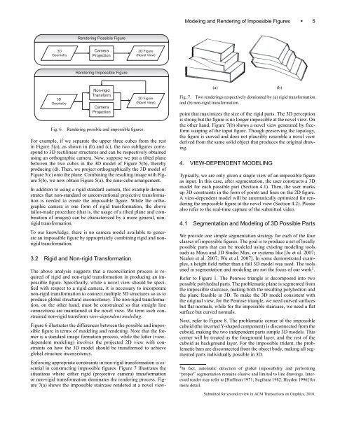
Rendering Possible Figure<br />
Camera<br />
Projection<br />
Rendering Impossible Figure<br />
Non-rigid<br />
Transform<br />
Camera<br />
Projection<br />
Fig. 6. Rendering possible and impossible figures.<br />
2D Figure<br />
(Novel View)<br />
2D Figure<br />
(Novel View)<br />
For example, if we separate the upper three cubes from the rest<br />
in Figure 5(a), as shown in (b) and (c), the two subfigures correspond<br />
to 3D rectilinear structures and can be respectively obtained<br />
using an orthographic camera. Now, suppose we put a tilted plane<br />
between the two cubes in the 3D model of Figure 5(b), thereby<br />
producing (d). Then, we project orthographically the 3D model of<br />
Figure 5(c) onto the plane. Combining the resulting image with Figure<br />
5(b), we now obtain Figure 5(a), the nine-cube arrangement.<br />
In addition to using a rigid standard camera, this example demonstrates<br />
that non-standard or unconventional projective transformation<br />
is needed to create the impossible figure. While the orthographic<br />
camera is one form of rigid transformation, the above<br />
tailor-made procedure (that is, the usage of a tilted plane and combination<br />
of images) can be characterized by a more general, nonrigid<br />
transformation.<br />
To our knowledge, there is no camera model available to generate<br />
an impossible figure by appropriately combining rigid and nonrigid<br />
transformation.<br />
3.2 Rigid and Non-rigid Transformation<br />
The above analysis suggests that a reconciliation process is required<br />
of rigid and non-rigid transformation in producing an impossible<br />
figure. Specifically, while a novel view should be specified<br />
with respect to a rigid camera, it is necessary to incorporate<br />
non-rigid transformation to connect multiple 3D structures so as to<br />
produce global structural inconsistency. The non-rigid transformation,<br />
on the other hand, must be constrained so that straight line<br />
connections are maintained at the novel view. We term such constrained<br />
non-rigid transform view-dependent modeling.<br />
Figure 6 illustrates the differences between the possible and impossible<br />
figure in terms of modeling and rendering. Note that the former<br />
is a standard image formation process, while the latter (viewdependent<br />
modeling) involves the projected 2D view with constraints<br />
on how the 3D model should be transformed to achieve<br />
global structure inconsistency.<br />
Enforcing appropriate constraints in non-rigid transformation is essential<br />
in constructing impossible figures. Figure 7 illustrates the<br />
situations where either rigid (projective camera) transformation<br />
or non-rigid transformation dominates the rendering process. Figure<br />
7(a) shows the impossible staircase rendered at a novel view-<br />
Modeling and Rendering of Impossible Figures • 5<br />
(a) (b)<br />
Fig. 7. Two renderings respectively dominated by (a) rigid transformation<br />
and (b) non-rigid transformation.<br />
point that maximizes the size of the rigid parts. The 3D perception<br />
is strong but the figure is no longer impossible at the novel view. On<br />
the other hand, Figure 7(b) shows a novel view generated by freeform<br />
warping of the input figure. Though preserving the topology,<br />
the figure is curved and does not plausibly resemble a novel view<br />
derived from the same solid object that produces the original drawing.<br />
4. VIEW-DEPENDENT MODELING<br />
Typically, we are only given a single view of an impossible figure<br />
as input. In this case, after segmentation, the user constructs a 3D<br />
model for each possible part (Section 4.1). Then, the user marks<br />
up 3D constraints in the form of points and lines on the 2D figure.<br />
A view-dependent model will be automatically optimized for rendering<br />
the impossible figure at the novel view (Section 4.2). Please<br />
also refer to the real-time capture of the submitted video.<br />
4.1 Segmentation and Modeling of 3D Possible Parts<br />
We provide one simple segmentation strategy for each of the four<br />
classes of impossible figures. The goal is to produce a set of locally<br />
possible parts that can be modeled using existing modeling tools<br />
such as Maya and 3D Studio Max, or systems like [Ju et al. 2007;<br />
Nealen et al. 2007; Wu et al. 2007]. In some demonstrated examples,<br />
a height field rather than a full 3D model was used. The tools<br />
used in segmentation and modeling are not the focus of our work 2 .<br />
Refer to Figure 1. The Penrose triangle is decomposed into two<br />
possible polyhedral parts. The problematic plane is segmented from<br />
the impossible staircase, making both the resulting polyhedron and<br />
the plane feasible in 3D. To make the 3D model consistent with<br />
the original view, for the Penrose triangle, we need curved surfaces<br />
but flat normals, while for the impossible staircase, we need a flat<br />
surface but curved normals.<br />
Next, refer to Figure 8. The problematic corner of the impossible<br />
cuboid (the inverted Y-shaped component) is disconnected from the<br />
cuboid, making the two independent parts simple 3D models. This<br />
corner will be treated as the foreground layer, and the rest of the<br />
cuboid as background layer. For the impossible trident, the problematic<br />
bars are disconnected from the object body, making all segmented<br />
parts individually possible in 3D.<br />
2 In fact, automatic detection of global impossibility and performing<br />
“proper” segmentation remains elusive and limited to line drawings. Interested<br />
reader may refer to [Huffman 1971; Sugihara 1982; Heyden 1996] for<br />
more detail.<br />
Submitted for second review in ACM Transactions on Graphics, 2010.