ptdist - Nanyang Technological University
ptdist - Nanyang Technological University
ptdist - Nanyang Technological University

You also want an ePaper? Increase the reach of your titles
YUMPU automatically turns print PDFs into web optimized ePapers that Google loves.
Dual Poisson-Disk Tiling:<br />
An Efficient Method for Distributing Features<br />
on Arbitrary Surfaces<br />
(minor revision version)<br />
Hongwei Li Kui-Yip Lo Man-Kang Leung Chi-Wing Fu<br />
lihw@cse.ust.hk csfelix@cse.ust.hk cskang@cse.ust.hk cwfu@cse.ust.hk<br />
Hongwei Li<br />
The Hong Kong <strong>University</strong> of Science and Technology<br />
Department of Computer Science and Engineering,<br />
The Hong Kong <strong>University</strong> of Science & Technology, Clear Water Bay, Hong Kong.<br />
Email: lihw@cse.ust.hk<br />
Kui-Yip Lo<br />
Department of Computer Science and Engineering,<br />
The Hong Kong <strong>University</strong> of Science & Technology, Clear Water Bay, Hong Kong.<br />
Email: csfelix@cse.ust.hk<br />
Man-Kang Leung<br />
Department of Computer Science and Engineering,<br />
The Hong Kong <strong>University</strong> of Science & Technology, Clear Water Bay, Hong Kong.<br />
Email: cskang@cse.ust.hk<br />
Chi-Wing Fu (* Corresponding author)<br />
Department of Computer Science and Engineering,<br />
The Hong Kong <strong>University</strong> of Science & Technology, Clear Water Bay, Hong Kong.<br />
Tel: +852-2358-6991 Fax: +852-2358-1477 Email: cwfu@cse.ust.hk / cwfu@acm.org<br />
February 2, 2008 MINOR REVISION<br />
1
Dual Poisson-Disk Tiling: An Efficient Method for<br />
Distributing Features on Arbitrary Surfaces<br />
Surface modeling applications: Distributing different kinds of features on HOLES3.<br />
Abstract<br />
This paper introduces a novel surface-modeling method to stochastically distribute features on<br />
arbitrary topological surfaces. The generated distribution of features follows the Poisson disk distribution,<br />
so we can have a minimum separation guarantee between features and avoid feature overlap. With the<br />
proposed method, we not only can interactively adjust and edit features with the help of the proposed<br />
Poisson disk map, but can also efficiently re-distribute features on object surfaces.<br />
The underlying mechanism is our dual tiling scheme, known as the Dual Poisson-Disk Tiling. First,<br />
we compute the dual of a given surface parameterization, and tile the dual surface by our specially-<br />
designed dual tiles; during the pre-processing, the Poisson disk distribution has been pre-generated on<br />
these tiles. By dual tiling, we can nicely avoid the problem of corner heterogeneity when tiling arbitrary<br />
parameterized surfaces, and can also reduce the tile set complexity. Furthermore, the dual tiling scheme<br />
is non-periodic, and we can also maintain a manageable tile set. To demonstrate the applicability of<br />
this technique, we explore a number of surface-modeling applications: pattern and shape distribution,<br />
bump-mapping, illustrative rendering, mold simulation, the modeling of separable features in texture<br />
and BTF, and the distribution of geometric textures in shell space.<br />
Index Terms<br />
I.3.7 Three-Dimensional Graphics and Realism, I.3.5 Computational Geometry and Object Model-<br />
ing, I.3.8 Applications<br />
February 2, 2008 MINOR REVISION<br />
1
I. INTRODUCTION<br />
Surface modeling is a significant element in computer graphics. It helps to increase the surface<br />
complexity on 3D objects, and hence improve the visual realism in the rendering. Since most<br />
3D objects we employed nowadays are still surface-based, surface modeling is yet a highly<br />
significant issue to address at present.<br />
In principle, surface modeling can be categorized into the following three major approaches:<br />
texture mapping approach, geometry approach, and shell mapping approach. The texture mapping<br />
approach, pioneered by Catmull [4], defines a mapping between a 2D rectangular image and<br />
a 3D target model, and maps surface data, such as colors [4], normals [2], the bidirectional<br />
texture functions (BTF) [10], [53], [62], the irradiance field in shell texture function [5], the<br />
BSSRDF in sub-surface light transport [22], [52], and even volumetric features such as fur [24],<br />
[34], onto the related model surface. Unlike texture mapping, the geometry approach [17], [1],<br />
[28], [63] truly constructs geometric details on model surfaces, and thus can avoid problems<br />
such as the non-uniformity in surface map, texture aliasing, and texture filtering; however, due<br />
to the complexity of the introduced geometric details, the amount of geometry primitives to be<br />
processed by the graphics hardware could be excessively large. The shell mapping approach [45],<br />
[47], [16], [46] bridges the gap between the above two approaches by attaching a shell volume<br />
on the model surface. By using this shell volume as a volumetric space for mapping, we can<br />
precisely map geometric models onto the object surface as if we perform texture mapping in<br />
a continuous volumetric fashion. Hence, we can attain higher flexibility and efficiency in the<br />
surface modeling process, and employ both discrete and continuous surface data originated from<br />
the texture mapping and geometry approaches at the same time.<br />
A. Motivation<br />
This paper explores the use of Wang tiling [55], [56] and the Poisson disk distribution to enrich<br />
the surface modeling capability provided by the above three approaches. We introduce the Dual<br />
Poisson-Disk tiling scheme to stochastically distribute features on surfaces of 3D models. The<br />
generated distribution pattern follows the Poisson disk distribution and our method can work on<br />
parameterized surfaces of arbitrary topology. To demonstrate the applicability of our method,<br />
we explore several different surface modeling applications, covering the three surface modeling<br />
approaches mentioned above; related rendering results are presented in Section V.<br />
February 2, 2008 MINOR REVISION<br />
2
Since we focus on tiling parameterized surfaces of arbitrary topology, the tiling mechanism is<br />
quite different as compared to tiling on planar domain. The vertex (tile corner) incidence on the<br />
surface parameterization grid is no longer a constant, i.e., 4; rather, the incidence could be 3, 5,<br />
or even 6. To overcome this tile corner heterogeneity problem, if we simply exhaust all possible<br />
corner, edge, and interior tile decompositions, e.g., by extending the tiling scheme in [31], we<br />
could end up creating an enormous tile set that is too complicated for management. On the other<br />
hand, if we just employ conventional Wang tiling [48], [8] or the template Poisson disk tiling<br />
methods [30], which promises a very small tile set, we could not properly handle the surface<br />
topology and maintain distribution correctness across tile boundaries.<br />
B. Contributions<br />
This paper presents a novel tiling method, called the Dual Poisson-Disk Tiling, to handle<br />
surfaces of arbitrary topology. Here we list the major contributions of this paper:<br />
1) The major contribution of this paper is the Dual Poisson-Disk Tiling scheme; this dual<br />
tiling idea makes tile-based Poisson disk distribution applicable to parameterized surfaces<br />
of arbitrary topology. Its advantages include: 1) The proposed dual tiling scheme can nicely<br />
avoid the tile corner heterogeneity problem and allows us to properly tile parameterized<br />
surfaces of arbitrary topology; 2) The size of the tile set is relatively small and manageable;<br />
3) It allows us to efficiently layout tiles on parameterized surfaces non-periodically.<br />
2) Secondly, we propose a rendering mechanism called the Poisson disk map; it enables<br />
interactive feature editing through the support of GPU fragment programming.<br />
3) Lastly, our distribution method brings in a wide range of applications, especially in the<br />
area of surface modeling, see Section V for the demonstration.<br />
C. Related work<br />
The distribution pattern we employed in our surface modeling applications is the Poisson disk<br />
distribution. Due to its blue noise properties [60], [61], [9], it is generally accepted as one of the<br />
best distribution pattern for sampling, and is widely used in computer graphics: anti-aliasing [12],<br />
[9], [40], ray tracing [41], and primitive distribution in illustrative rendering [11].<br />
In general, the Poisson disk distribution is a uniform distribution of points, where all point-<br />
to-point distances are no less than a certain limit. In other words, if we put a circular disk of<br />
February 2, 2008 MINOR REVISION<br />
3
adius equal to half of this limit at each distributed point, we can guarantee no overlapping disks.<br />
Based on this property, if we use the Poisson disk distribution as a mean to distribute features<br />
on surfaces, we can effectively avoid feature overlap.<br />
Generating the Poisson disk distribution Traditionally, the generation of the Poisson disk<br />
distribution is based on the dart throwing algorithm [9]. Points are successively placed in a<br />
finite area at random, and a point is accepted only if the point-to-point distance limit is not<br />
violated. Since this algorithm requires numerous amount of checking, it is computationally<br />
very expensive. To address this issue, some faster algorithms [12], [40], [41], [26] have been<br />
proposed for speedup, and in particular, McCool and Fiume [39] developed an improved version<br />
of dart throwing by gradually reducing the distance limit. Lloyd’s relaxation method [36] is<br />
further employed to optimize the point distribution by jittering the generated points towards<br />
their corresponding Voronoi centroids. At present, research in speeding up the dart throwing<br />
algorithm is still very active; Jones [23] applied Voronoi diagram; Dunbar and Humphreys [14]<br />
applied the idea of scalloped sectors, to represent available regions for dart throwing; White [59]<br />
improved the traditional dart-throwing algorithm by using quadtree subdivision on the sampling<br />
domain.<br />
The Wang tile approach Stam [50] was the first in applying Wang tiles [55], [56] to computer<br />
graphics; by synthesizing matchable texture patterns on Wang tiles, textures can be arranged on<br />
two-dimensional manifolds in a non-periodic manner. Furthering this idea, Hiller et al. [21]<br />
invented a new approach to generate the Poisson disk distribution using tiling. Rather than<br />
generating one point at a time, they employed Wang tiles as point set containers with the<br />
Poisson disk distribution pre-synthesized on tiles; thus, we can match color-coded edges between<br />
Wang tiles, and quickly generate a tile-based Poisson disk distribution on a 2D domain. Cohen<br />
et al. [48], [8] furthered this approach and presented a stochastic tiling algorithm so that we<br />
can efficiently generate the Poisson disk distribution. Recently, Kopf et al. [27] proposed the<br />
recursive Wang tile method so that we can control distribution density at different spatial scales. In<br />
addition to two-dimensional domain [50], [21], [48], [8], [57], Wang tiles have been generalized<br />
to handle spaces such as the three-dimensional domain using Wang cubes [49], [37], [33], [38]<br />
and arbitrary topological surface using signed Wang tiles [19], [35]. Other than Wang tiling,<br />
Ostromoukhov et al. [43] applied Penrose tiling to distribute points for importance sampling.<br />
February 2, 2008 MINOR REVISION<br />
4
In addition, Ostromoukhov [42] proposed using polyomino subdivision to generate distributions<br />
with blue-noise properties.<br />
The Poisson disk tiles Lagae and Dutré [29] developed a procedural approach for efficiently<br />
evaluating the Poisson disk distribution. The proposed Poisson disk tiles is a variation of Wang<br />
tiles, where the square tile region is divided into three disjoint parts: corner tiles, edge tiles, and<br />
interior tiles. These three kinds of tiles are pre-generated sequentially conforming to the Poisson<br />
disk distribution, and they are finally re-assembled together to tile a given 2D domain by color<br />
matching. Since corner and edge regions are introduced in this tiling scheme, we can improve<br />
the distribution quality, particularly around corner regions.<br />
In addition to Poisson disk tiles, Lagae and Dutré [30] invented another interesting tiling<br />
scheme, called the Template Poisson disk tiles. It is a toroidal version of Wang tiles with one<br />
single edge color in the entire tile set, so that we can create a single tileable frame (with margin<br />
border only) and synthesize additional tiles by using the same frame as the boundary condition.<br />
Recently, Lagae and Dutré [31] proposed an alternative tile-based method to generate the<br />
Poisson disk distribution; it is a corner-based tiling scheme with color-coded corners. Hence,<br />
we can further improve the distribution quality around corner regions, see [32] for a detailed<br />
analysis and comparison of various methods that generate the Poisson disk distribution in 2D.<br />
Moreover, Lagae and Dutré [33] also explored their tile-based schemes in three-dimensional<br />
space and proposed the generation of Poisson sphere distributions by tiling Wang cubes.<br />
Wang tiles on arbitrary surfaces Fu and Leung [19], [35] generalized the conventional Wang<br />
tiling method using signed Wang tiles, and made texture tiling applicable to arbitrary topological<br />
surfaces. However, since this tiling scheme does not take corner heterogeneity into account, this<br />
scheme cannot be used to generate the Poisson disk distribution on arbitrary surfaces.<br />
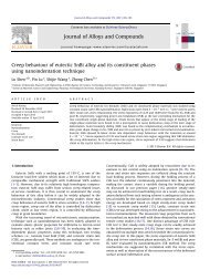
Fig. 1. Overview of our surface modeling method.<br />
February 2, 2008 MINOR REVISION<br />
5
D. Overview<br />
Figure 1 outlines our surface modeling method. It involves four main tasks in total, and takes<br />
a parameterized surface as its input. Any surface parameterization method [15], [18], [7], [3],<br />
[51], [20], [25], [13] can be used to create this input as long as the given parameterization is<br />
quad-based and has low distortion in the surface mapping.<br />
Following this input, our first task is to compute the dual of the parameterized surface and<br />
pass the generated dual surface to the stochastic tiling task later on. However, unlike other offline<br />
tasks, the tile set generation is surface independent, so we can pre-construct a dual Poisson-disk<br />
tile set that stores the Poisson disk distribution. Section III details the generation process, while<br />
Section IV introduces the stochastic tiling task for arranging the generated tiles on dual surfaces.<br />
Finally, based on the distributed points on object surface, we can construct the Poisson disk map,<br />
and implement various surface modeling applications, see Section V.<br />
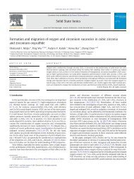
II. THE DUAL SURFACE<br />
As pointed out in Section I-A, when tiling a parameterized surface of arbitrary topology, tile<br />
corners could be shared by three, four, five, or even six tiles [13], see Figure 2; we cannot properly<br />
ensure distribution correctness across tile corners if we simply apply conventional tiling schemes<br />
on parameterized surfaces of arbitrary topology. To address this problem, our first strategy is to<br />
create a dual surface, so that we can make every tile corner to be shared exactly by 4 tiles all<br />
over the surface. By this means, we can avoid complex cases like irregular tile corner regions<br />
with 3, 5 or even more incident tiles, and thus can significantly reduce the tile set size because<br />
we only have one form of corner tiles in our scheme, see Section III.<br />
Fig. 2. The tile corner heterogeneity.<br />
February 2, 2008 MINOR REVISION<br />
6
Fig. 3. (a) Input surface; (b) We connect neighboring edge midpoints on the input surface to generate the dual surface. The<br />
dotted lines are edges of the dual surface; (c) The dual surface is composed of Tri-tiles, Quad-tiles, and Quin-tiles.<br />
To construct dual surfaces, we first take edge midpoints in the input surface parameterization as<br />
vertices of the dual surface to be generated. Then, we connect each midpoint to every neighboring<br />
midpoint on the same subquad belonging to the original surface parameterization, see Figure 3<br />
for an illustrative example. After this dual transform, we have three kinds of interior tiles in<br />
our tile set: Tri-tile, Quad-tile, and Quin-tile, corresponding to the interior regions bounded by<br />
3, 4, and 5 tile corners, respectively, but now, we only have one kind of corner junction over<br />
the entire model surface. Depending on the surface parameterization, we somehow could have<br />
Sex-tile for interior regions bounded by 6 tile corners.<br />
III. CONSTRUCTING A DUAL TILE SET<br />
The dual Poisson-disk tile set is generated using the corner-edge-interior decomposition [29],<br />
see Figure 9 for an example tiling. With the dual transform, we only have one form (shape)<br />
of corner tiles (and edge tiles), while interior tiles can take several forms: Tri-tile, Quad-tile,<br />
Quin-tile, etc. The size of corner and edge tiles are determined by the Poisson disk radius, so<br />
that any Poisson disk placed on the interior tiles cannot affect any other disk in neighboring<br />
interior tiles. Hence, we first create corner tiles, and then edge tiles in our tile set construction,<br />
and employ these tiles to generate Tri-tiles, Quad-tiles, Quin-tiles, etc.<br />
Furthermore, unlike regular Wang tiles that have a fixed orientation, we have to allow tile<br />
rotation in our case because we work on surfaces of arbitrary topology. Therefore, our corner<br />
tiles, edge tiles, and interior tiles are all rotatable, and the tile matching condition is determined<br />
not only by the tile colors, but also by the tile orientations relative to corner tiles as well.<br />
February 2, 2008 MINOR REVISION<br />
7
Fig. 4. The construction of a corner tile.<br />
A. Constructing Corner Tiles<br />
Similar to the idea of colored corners in [31], we arrange colors at corners, rather than on<br />
edges. Here we have C colors and hence C different corner tiles. Each corner tile takes the<br />
shape of a regular octagon with side length exactly equal to 2R, where R is the Poisson disk<br />
radius. Figure 4 shows the corner tile construction procedure. Firstly, we employ relaxation dart<br />
throwing to dissipate N points onto a unit square region, and Lloyd’s relaxation to optimize<br />
the distribution. Then, an octagon region is cut out of the distribution to form a corner tile; by<br />
independently repeating this construction process C times, we can generate all C corner tiles.<br />
To guarantee a good distribution quality in the final tiling, we further have to compare these<br />
C corner tiles after the synthesis, and re-generate any corner tile (among the C corner tiles) that<br />
is too similar in distribution as compared to others in the corner tile set.<br />
B. Constructing Edge Tiles<br />
After creating corner tiles, the next step is to generate edge tiles. Figure 5 shows the edge tile<br />
construction procedure. Here we first put two corner tiles at the two opposite ends of an edge<br />
tile to be generated (Figure 5(a)). Then, we constrain the point distribution by the points pre-<br />
generated inside the two corner tiles, and we apply relaxation dart throwing to fill the remaining<br />
empty area. Next, we carry out a number of Lloyd’s relaxation to fine-tune the distribution<br />
(Figure 5(b)). Note that during the dart throwing and relaxation, new points are prohibited from<br />
entering the corner regions, so that we can ensure proper distribution matching while matching<br />
corner tiles and edge tiles in the tiling. Finally, we extract the points inside the edge tile region<br />
and produce an edge tile. The thickness of an edge tile is 2R.<br />
February 2, 2008 MINOR REVISION<br />
8
Fig. 5. The construction of an edge tile. The black triangles attached to the corner tiles indicate the corner-tile orientation.<br />
Rotational Symmetry in Edge Tiles Since corner tiles are rotatable, each corner tile could<br />
have four possible axis-to-axis orientations relative to the edge tile being constructed. Hence,<br />
we could have as many as (4C) 2 different edge tiles in total. However, because of rotational<br />
symmetry, some edge tiles are in fact equivalent in terms of tileability. Figure 6 shows an<br />
example edge tile set with one single corner color; we label top, bottom, left, and right sides<br />
of a corner tile as T, B, L, and R, respectively; for instance, edge 1 and edge 11 shown in the<br />
figure is a symmetric pair, while edge 3 is self-symmetric.<br />
Fig. 6. Rotational symmetry in edge tiles; we have six symmetric pairs: 1 and 11, 2 and 15, 4 and 7, 5 and 12, 10 and 13, as<br />
well as 6 and 16, whereas the other four edges (3, 8, 9, and 14) are self-symmetric. Thus, there are totally 10 unique edges.<br />
Since our tile matching scheme is based solely on corner color and corner orientation, we<br />
have to enforce edge tile uniqueness, so that after we layout all corner tiles on the dual surface,<br />
we can uniquely determine which edge tile to be placed in-between each pair of corner tiles,<br />
as well as which interior tile to be placed inside a ring of corner tiles. Otherwise, we will have<br />
to add additional color code (diversity) to edge tiles, and escalate the tile set complexity and<br />
size. In this way, within the 16 possible combinations shown in the figure above, we have to<br />
determine the symmetric pairs and generate only one edge tile for each pair found.<br />
February 2, 2008 MINOR REVISION<br />
9
Further than that, we need to specially handle self-symmetric edges, e.g., edge 3 shown in the<br />
figure. The point distribution inside a self-symmetric edge tile has to be rotationally symmetric.<br />
Otherwise, we could have two ways in placing these edge tiles in a tiling, and escalate the tile set<br />
complexity; this is similar to tagging additional colors on edges and expanding the tile set size.<br />
Note that to construct a self-symmetric edge tile, we have to constrain the initial dart throwing<br />
and the Lloyd’s relaxation process to enforce rotational symmetry during the tile construction.<br />
C. Constructing Interior Tiles<br />
After corner tiles and edge tiles, we can move on to create the interior tiles: Tri-tiles, Quad-<br />
tiles, Quin-tiles, etc.<br />
Quad-tiles Figure 7 shows the construction procedure of Quad-tiles. Similar to edge tiles, we<br />
first assemble an appropriate configuration of 4 corner tiles and pick up related edge tiles to form<br />
a frame (Figure 7(a)). Then, we apply relaxation dart throwing followed by Lloyd’s relaxation<br />
to generate the point distribution in the interior region (Figure 7(b)). Again, new points cannot<br />
enter the corner and edge regions during the dart throwing and relaxation process, while points<br />
originally in the corner and edge tiles are fixed throughout the construction process.<br />
Fig. 7. The construction of a Quad-tile. The black triangles attached to the corner tiles indicate the corner-tile orientation.<br />
Furthermore, we also explore rotational symmetry in interior tiles and generate only unique<br />
interior tiles. However, it is worth to note that removing duplicated interior tiles, e.g., Quad-tiles,<br />
is not as critical as removing duplicated edge tiles. For edge tiles, if we ignore tile uniqueness,<br />
we could escalate the tile set complexity because we need more interior tiles to match different<br />
edge tiles introduced, even when the colors and orientations of the boundary corner tiles are the<br />
same; but for interior tiles, since the points added inside the interior tiles never affect points<br />
February 2, 2008 MINOR REVISION<br />
10
Fig. 8. The construction of a Tri-tile (above) and a Quin-tile (below); the warping method is employed here.<br />
elsewhere in any other tile (different from points in the edge tiles), having duplicated interior<br />
tiles will increase the tile set size, but not the tile set complexity.<br />
Tri-tiles and Quin-tiles As compared to Quad-tiles, the construction of Tri-tiles and Quin-<br />
tiles are more complicated because these tiles are intrinsically non-planar, see Figures 8(a) and<br />
(e). To address this problem, we propose two methods to generate non-planar interior tiles:<br />
• The first method employs geodesic distance and jitters the distributed point samples directly<br />
on the non-planar domain. After we make up a tile frame using corner tiles and edge tiles,<br />
see Figures 8(a) and (e), we apply dart throwing in the interior area, and employ geodesic<br />
distances to construct a Delaunay triangulation for all points distributed so far, including<br />
also the points on the corner tiles and edge tiles. Finally, we apply Lloyd’s relaxation in<br />
this non-planar domain and fine-tune the point distribution inside.<br />
• The second method is based on the observation that when we arrange non-planar tiles such<br />
as Tri-tiles and Quin-tiles on object surfaces, the surface regions covered by these tiles are<br />
usually highly smooth and planar. Hence, if we employ the first approach to arrange point<br />
samples with same density as that on Quad-tiles, we could end up having a relatively denser<br />
point distribution on the surface regions covered by non-planar tiles. Therefore, we propose<br />
to warp the non-planar region to a planar domain, distribute and relax points directly on<br />
February 2, 2008 MINOR REVISION<br />
11
it, and finally map the distributed points back to the object surface. In detail, we employ<br />
equilateral triangle and regular pentagon, as the warped domains for Tri-tiles and Quin-tiles,<br />
respectively, see Figures 8(b) and (c), and barycentric coordinate mapping to perform the<br />
warping. Furthermore, like what we have done for Quad-tiles, we also forbid any newly<br />
added point to enter the corner tile and edge tile regions in the warped domain during the<br />
tile construction process. Also, we can construct the Sex-Tiles in a similar way, but rather<br />
than using an equilateral triangle or pentagon as in the cases of the Tri-tiles and Quin-tiles,<br />
respectively, we use a regular hexagon on the planar domain.<br />
D. Size of a dual Poisson-disk tile set<br />
In this subsection, we examine the size of a complete dual Poisson-disk tile set; the Cauchy-<br />
Frobenius lemma [58] (also known as the orbit-counting theorem) is used in the analysis, so that<br />
we can take rotational symmetry into consideration, and determine the number of unique edge<br />
tiles and interior tiles in a dual Poisson-disk tile set.<br />
Edge tiles Let E be the set of all possible edge tile configurations without considering rotational<br />
symmetry, i.e., |E| = (4C) 2 . Let G be a finite group that acts on E. For each g ∈ G, let E g denote<br />
the set of elements in E that are fixed by g. For edge tiles, we have two g’s in G: one is an<br />
identity, say g0, and hence, E g0 = (4C) 2 ; the other one is an 180-degree rotation (in 2D), say<br />
g1, and we have E g1 = 4C because only four edge tiles per color (the two neighboring corner<br />
tiles having the same color) are identical after an 180-degree rotation. Therefore, by using the<br />
Cauchy-Frobenius lemma, the number of unique edge tiles under rotational symmetry is:<br />
|E/G| = 1<br />
|G|<br />
<br />
g∈G<br />
|E g | = 1<br />
2 ((4C)2 + 4C) = 8C 2 + 2C .<br />
Interior tiles For Quad-tiles, we have four possible operations: an identity, a 90-degree<br />
clockwise rotation, an 180-degree clockwise rotation, and a 270-degree clockwise rotation. By<br />
counting the number of fixed elements under each of them, we can again apply the Cauchy-<br />
Frobenius lemma to find out the number of unique Quad-tiles under rotational symmetry:<br />
|Q/G| = 1<br />
|G|<br />
<br />
g∈G<br />
|Q g | = 1<br />
4 ((4C)4 + 4C + (4C) 2 + 4C) = 64C 4 + 4C 2 + 2C ,<br />
February 2, 2008 MINOR REVISION<br />
12
where G is a finite group acting on the full Quad-tile set Q. Using a similar method, we can<br />
also compute the number of unique Tri-tiles and Quin-tiles under rotational symmetry. Table I<br />
summarizes the size of a dual Poisson-disk tile set. Note that we normally do not need a full set<br />
of Quin-tiles; a relatively small amount of them are sufficient for stochastic tiling, see Section IV.<br />
TABLE I<br />
THE SIZE OF A DUAL POISSON-DISK TILE SET.<br />
Num. of Colors Num. of Corner Tiles Num. of Edge Tiles Num. of Tri-tiles Num. of Quad-tiles Num. of Quin-tiles<br />
1 1 10 24 70 208<br />
2 2 36 176 1044 6560<br />
3 3 78 584 5226 49776<br />
C C 8C 2 + 2C<br />
1<br />
3 (64C3 + 8C) 64C 4 + 4C 2 + 2C<br />
16<br />
5 (64C5 + C)<br />
Comparing to standard tiling scheme Without using dual tiling, conventional tiling schemes,<br />
for example, the corner-edge-interior decomposition, will result in different kinds of corner tiles<br />
because we work on surfaces of arbitrary topology. A corner tile could meet with three, four,<br />
five, or even six edge tiles unlike the case we have in dual tiling. As a result, the set of corner<br />
tiles will become more complex even we consider only a small number of colors in the tiling.<br />
Note that these corner tiles need to be rotatable; hence, such a complexity could further affect<br />
the size of the edge tile set and the interior tile set as well.<br />
For instance, if C is the number of colors we have for each kind of corner tiles, that is, we<br />
have C 3-corner tiles, C 4-corner tiles, and C 5-corner tiles, etc. When we consider edge tiles,<br />
we have to consider several kinds of edge tiles: edge tiles joining two 3-corner tiles, edge tiles<br />
joining one 3-corner tile and one 4-corner tile, etc. It unavoidably complicates the edge tile set<br />
as well as the interior tile set that follows. Moreover, it will also significantly increase the tile<br />
set size as well. By dual tiling, we can avoid such a complexity and keep a compact corner tile<br />
set; hence, we can also maintain manageable sets of edge tiles and interior tiles.<br />
A. The Dual Tiling Algorithm<br />
IV. THE DUAL TILING ALGORITHM<br />
We have the following steps in applying our dual Poisson-disk tile set to generate the Poisson<br />
disk distribution on dual surfaces; stochastic tiling [31] is used in our algorithm.<br />
February 2, 2008 MINOR REVISION<br />
13
• First of all, we properly assign Quin-tiles available in our tile set onto the Quin-tile slots<br />
on the dual surface. Since conventional surface parameterization methods normally produce<br />
very few 5-corner (as well as 6-corner) junctions (as compared to 4-corner junctions) on<br />
the surface parameterizations, we normally do not have many Quin-tile slots (as well as<br />
Sex-tiles) on the dual surface, as compared to Quad-tile slots. Therefore, a relatively small<br />
amount of Quin-tiles (and Sex-tiles) are sufficient in our stochastic tiling. Furthermore, in<br />
extreme cases where Quin-tile slots dominate, we can make use of one or two corner colors<br />
to generate a full set of Quin-tile set (See Table I); then, we can still guarantee an agreeing<br />
tiling.<br />
• After arranging Quin-tiles, we randomly assign colors and orientations to the remaining<br />
corner tile slots on the dual surface. Since we have a complete set of Tri-tiles and Quad-<br />
tiles, we do not need to constrain the corner tile assignment as we did for Quin-tiles.<br />
• Finally, based on the arranged corner tiles, we can lookup related edge tiles and then Quad-<br />
tiles and Tri-tiles to fill the remaining space on the dual surface.<br />
In our actual implementation, we develop a tile-reassembling scheme to facilitate the tiling<br />
process. After we generate the whole dual tile set, we expand the region of each interior tile to<br />
include parts of the related corner and edge tiles. Since interior tiles and edge tiles are unique,<br />
given any interior tile, we can uniquely determine its boundary corner and edge tiles, pack<br />
half of the related edge tiles and a quarter of the related corner tiles around it, and generate<br />
a reassembled tile for each interior tile, see Figure 7(c), Figure 8(d), and Figure 8(h) for a<br />
reassembled Quad-tile, Tri-tile, and Quin-tile, respectively. In this way, we can replace corner<br />
tiles, edge tiles, and interior tiles by the reassembled tiles in our implementation, and hence<br />
simplify our data structure, and make the tiling more convenient.<br />
B. Tiling Examples<br />
Figure 9 presents a tiling example to exemplify how we tile a non-planar surface in the form<br />
of a T-shape brick with our dual Poisson-disk tiles. Here we have C = 2 and N = 32, where C is<br />
the number of colors (corner tiles) and N is the point distribution density. In this example, we<br />
can see that we have four Quin-tiles and twelve Tri-tiles, whereas all corner tiles meet exactly<br />
four edge tiles over the entire model surface due to dual tiling.<br />
February 2, 2008 MINOR REVISION<br />
14
Fig. 9. A tiling example – Generating the Poisson disk distribution on a dual parameterized surface in the form of a T-shape<br />
brick; C = 2 and N = 32. The black quadrants on the corner tiles indicate the corner-tile orientation.<br />
In addition, we also present the tiling of a two-dimensional plane using our tiling scheme,<br />
see Figure 10. Since the tiling domain is now planar, we only need corner tiles, edge tiles, and<br />
Quad-tiles, but not Tri-tiles and Quin-tiles. Moreover, the corner tiles can be placed at the grid<br />
junctions, rather than at the edge mid-points. Furthermore, since only corner tiles, edge tiles, and<br />
Quad-tiles are involved, this 2D tiling structure is very similar to the colored corner approach<br />
proposed in [31]; however, our corner tiles are rotatable and our tiling is dual-based, so that our<br />
method can handle parameterized surfaces of arbitrary topology.<br />
A. Implementation issues<br />
V. IMPLEMENTATION, ANALYSIS AND APPLICATIONS<br />
The Poisson disk map To support interactive control on distributed features, we developed<br />
the idea of Poisson disk map. It is basically a texture map defined on a parameterized surface,<br />
with each texel storing three values: (d, θ) is the polar coordinate of the pixel center measured<br />
from the nearest distributed feature point on object surface using geodesics (see Figure 11 for<br />
an example Poisson disk map), and feature index could be a unique feature ID associated with<br />
February 2, 2008 MINOR REVISION<br />
15
Fig. 10. A tiling example – Generating the Poisson disk distribution on a two-dimensional plane; C = 2 and N = 128.<br />
Fig. 11. An example Poisson disk map: the distance component d (left) and angular component θ (right) on LAURANA. Note<br />
that there are 874 points distributed on LAURANA, and the reference direction for θ is picked randomly at each point.<br />
February 2, 2008 MINOR REVISION<br />
16
that feature point or an integer denoting the color index resulted from k-coloring. Note that in<br />
the figure, red dots are additionally drawn on the LAURANA surface to indicate the location of<br />
feature points, and also, by using k-coloring, we can assign multiple colors and patterns to the<br />
distributed features and ensure no two neighboring features share the same color or pattern.<br />
In the renderings, we employ fragment programs on the GPU: 1) to retrieve (d, θ) and feature<br />
index for each pixel fragment, and 2) to compute the texture coordinates on the corresponding<br />
feature texture if the pixel fragment falls within an effective Poisson disk from a feature point.<br />
The advantage of having a Poisson disk map is that we can interactively deform and modify the<br />
features, for example, scaling or re-orientating the features without needing to build any form<br />
of static geometries for them, as well as editing the feature textures and reloading the feature<br />
appearance on objects interactively at run-time.<br />
Distribution refinement on object surface With our tiling method, we can precisely guarantee<br />
a valid Poisson disk distribution on parameterized surfaces, and this distribution guarantee can<br />
be carried to the object surface, provided the surface parameterization does not introduce any<br />
distortion. But as one might expect, since surfaces of 3D models are seldom flat, this is,<br />
however, rarely the case in practice. To address this issue so that we can produce a valid<br />
Poisson disk distribution on object surface, certain refinement process is unavoidable after<br />
the tiling. In our current implementation, we first refine the Delaunay triangulation (from the<br />
corresponding Voronoi diagram) mapped from the parameterized surface to the object surface,<br />
so that the resultant connectivity information can be truly defined on the object model; note<br />
that geodesics must be computed for connected edges on high curvature regions so as to<br />
ensure connectivity correctness. Then, we can precisely apply Lloyd’s relaxation locally at each<br />
distributed point and jitter them towards their Voronoi centroids on the object surface. Since the<br />
surface parameterization we used are of low distortion, the entire refinement process takes no<br />
more than a few minutes (around 10−20 iterations, depending on the number of distributed points<br />
and the parameterization complexity) to finish on a commodity PC: an HP xw4400 workstation<br />
with Intel Core(TM)2 CPU 6400 at 2.13GHz and 1GB Memory, see Table II for the timing<br />
result. Also, to fairly compare the refinement time against different 3D objects, and also against<br />
different number of distributed points, we use 20 iteration steps in all testing cases shown.<br />
Furthermore, note also in the table that the number of points in parameterization denotes the<br />
model complexity.<br />
February 2, 2008 MINOR REVISION<br />
17
TABLE II<br />
TIMING ON THE REFINEMENT PROCESS.<br />
3D Tile set Total number of Number of points Total time for<br />
models distributed points in parameterization refinement (sec.)<br />
C = 2, N = 16 3142 25596 5.4<br />
HOLES3 C = 2, N = 32 6360 25596 9.0<br />
C = 2, N = 64 12724 25596 19.2<br />
C = 2, N = 16 7039 14587 9.6<br />
LAURANA C = 2, N = 32 14082 14587 19.2<br />
C = 2, N = 64 27986 14587 39.0<br />
C = 2, N = 16 10121 82434 15.0<br />
BUNNY C = 2, N = 32 20380 82434 28.8<br />
C = 2, N = 64 40983 82434 58.8<br />
Now, one may argue why we employ tiling to generate the Poisson disk distribution on 3D<br />
models, while after-tiling refinement is still needed. In fact, if we do not use tiling, we have<br />
to do dart throwing and Lloyd’s relaxation to distribute points on object surfaces. It is a one-<br />
point-at-a-time process, and could be exceedingly time-consuming. By tiling, we can efficiently<br />
initialize a point distribution that is nearly a Poisson disk distribution, and this distribution can,<br />
in turn, be readily refined on object surface within a few iteration steps.<br />
B. Examining the Generated Distribution<br />
Spectral Analysis One common way to examine the quality of Poisson disk distributions is<br />
by using periodogram [54]. Here we experiment six different color and point density settings<br />
in our dual Poisson-disk tiling, and generate around 16,384 points on a 2D plane for each<br />
Poisson disk distribution being analyzed, see Figure 12. In addition, we also generate one Poisson<br />
disk distribution purely using dart throwing as a reference. From the figure, we can see that<br />
increasing the number of colors and distribution density can improve the distribution quality,<br />
which means that the resultant distribution could become less periodic. Moreover, if we compare<br />
the periodograms generated by our method against those by other tile-based methods [32], our<br />
method has one crucial difference; even with the same number of color code, we have additional<br />
variation in generating the Poisson disk distribution because our tiles are rotatable.<br />
Radius Statistics In addition, we also study the Poisson disk distributions that generated on<br />
surfaces using radius statistics [31]. Here we first have to compute two radius data: Rmax and r,<br />
February 2, 2008 MINOR REVISION<br />
18
Fig. 12. Periodograms of Poisson disk distributions generated with dual Poisson-disk tiles (a-f) and dart throwing (g).<br />
where Rmax is an upper bound of the Poisson disk radius given the total surface area and the<br />
distribution density, whereas r is the Poisson disk radius we have in the generated Poisson disk<br />
distribution.<br />
Rmax = (2 √ 3K/S) −1/2 ,<br />
where S is the total surface area and K/S is the distribution density. Here r is half of the shortest<br />
distance among neighboring point pairs distributed on the object surface. Furthermore, radius<br />
statistics measure the ratio ρ = r/Rmax to estimate the regularity of the generated distributions.<br />
A small ρ indicates an uneven distribution, while a large ρ indicates a regular distribution.<br />
According to Section 3.1 in [32], Poisson disk distributions should have a relative radius that<br />
is large (ρ > 0. 65), but not too large (ρ > 0. 90). Furthermore, it is worth noting that since the<br />
equation for estimating Rmax is originally for 2D planar domain, we have to assume sufficiently<br />
large point sets in our experiments, so that Rmax can serve as a good upper bound approximation<br />
even on non-planar surfaces. In practice, we can obtain ρ values of around 0. 3 to 0. 6 (on surfaces)<br />
after the tiling depending on the quality of the surface parameterization, and can quickly optimize<br />
ρ to be around 0. 7 to 0. 8 after distribution refinement. Table III presents some related results<br />
for HOLES3, BUNNY, and LAURANA before and after relaxation, while Figure 13 shows the<br />
generated distributions on BUNNY before and after relaxation. Note that we also compute mbefore<br />
February 2, 2008 MINOR REVISION<br />
19
and mafter (see the table); m refers to the average half-distance between neighboring point pairs<br />
on the object surface.<br />
HOLES3 (S = 1. 7258)<br />
BUNNY (S = 2. 3775)<br />
LAURANA (S = 1. 5414)<br />
TABLE III<br />
RADIUS STATISTICS.<br />
Tile set Rmax rbefore rafter mbefore mafter ρbefore ρafter<br />
C = 2, N = 16 0.0128 0.0077 0.0100 0.0131 0.1300 0.6052 0.7653<br />
C = 2, N = 32 0.0089 0.0050 0.0067 0.0091 0.0090 0.5677 0.7558<br />
C = 2, N = 64 0.0063 0.0033 0.0048 0.0064 0.0064 0.5310 0.7674<br />
C = 2, N = 16 0.0085 0.0031 0.0063 0.0086 0.0086 0.3660 0.7371<br />
C = 2, N = 32 0.0060 0.0016 0.0044 0.0061 0.0061 0.2591 0.7358<br />
C = 2, N = 64 0.0042 0.0012 0.0031 0.0043 0.0042 0.2749 0.7315<br />
C = 2, N = 16 0.0082 0.0029 0.0061 0.0083 0.0083 0.3594 0.7363<br />
C = 2, N = 32 0.0057 0.0024 0.0042 0.0058 0.0057 0.4219 0.7342<br />
C = 2, N = 64 0.0041 0.0015 0.0030 0.0041 0.0041 0.3658 0.7339<br />
Fig. 13. An example showing the distributions before and after the relaxation; the tile set in use is Bunny, C = 2, N = 16.<br />
C. Applications in Surface Modeling<br />
Figures 14-19 present the rendering results of five different surface modeling applications we<br />
briefly explored:<br />
February 2, 2008 MINOR REVISION<br />
20
Pattern and Shape distribution The most straightforward application of our tiling method is<br />
to distribute texture-based features like patterns and shapes on 3D models; Figure 14 demonstrates<br />
three different kinds of patterns distributed on HOLES3, BUNNY, and LAURANA. By storing<br />
patterns and shapes as small image textures, we can apply fragment program to lookup texture<br />
values based on the per-fragment values, (d, θ), sampled from the Poisson disk map. Furthermore,<br />
since the image textures in use are for texture lookup only, we can interactively modify, deform,<br />
and reload the texture-based patterns during the program run-time. Similarly, we use small bump<br />
maps (normal maps) storing distorted surface normals instead of colors, and apply a modified<br />
fragment program to lookup distorted surface normals. In this way, we can shade the object<br />
surfaces with bumpy appearance (see the bumpy BUNNY, LAURANA, and HOLES3 in Figure 15).<br />
Illustrative rendering To create the illustrative renderings shown in Figure 16, points are first<br />
distributed onto the object surface according to our tiling method; compared to other applications,<br />
we need far more points in illustrative rendering; in detail, they can be generated by subdividing<br />
the dual surface before the tiling, i.e., more tiles on the initial parameterized surfaces. For<br />
the examples shown in the figure, 27, 986 and 40, 983 points are generated on LAURANA and<br />
BUNNY, respectively. In addition, it is worth to note that since all distributed points have well-<br />
defined 3D locations on object surface (in object space), we can easily attain frame-to-frame<br />
coherency in the renderings subject to viewpoint changes.<br />
Mold Simulation Moreover, we also apply our distribution method to simulate mold growth.<br />
Similar to illustrative rendering, we first distribute a dense set of points on object surface, and<br />
compute the accessibility [6] (like ambient occlusion) at each distributed point in object space.<br />
Note that to compute the accessibility, we put a hemisphere aligned with the surface normal<br />
at each distributed point, and randomly send out hundreds of rays (over the hemisphere) from<br />
the distributed point. The accessibility is the percentage of rays that are not blocked by the<br />
object itself. Hence, the lower accessibility, the higher the chance (density) for mold to appear<br />
on that specific location. Hence, we apply the accessibility map as a filter to assign colors and<br />
transparency to distributed points, and simulate the mold growing process. Figure 17 shows<br />
molded HOLES3 and BUNNY.<br />
BTF synthesis Furthermore, we can also apply our tiling method to arrange the bidirectional<br />
texture functions (BTF) by keying BTF-based features on object surfaces. To create the BTF<br />
renderings shown in Figure 18, we first associate a BTF hole data with each distributed point<br />
February 2, 2008 MINOR REVISION<br />
21
on the object surface. Then, we can synthesize the BTF on the unfilled surface area on the 3D<br />
model by using constrained texture synthesis in the parameterized space. Hence, we can have<br />
BTF elements defined for all pixels on the parameterized surface, and hence, can render the<br />
model surface under variable illumination and viewing directions.<br />
However, we have to be very careful when transforming the per-fragment viewing and lighting<br />
vectors; the TBN transform [2], [44] has to align with the parameterized grid (rather than the<br />
local surface curvature) so that we can correctly lookup the surface reflectance defined in the<br />
BTF data space. Furthermore, it is worth to note that the advantage of using tiling for BTF is<br />
that we only need to keep a very small BTF data for the entire 3D model; in the rendering<br />
examples shown, the BTF hole data only has spatial resolution: 128 × 128 (29. 3MB in total,<br />
without spatial compression among BTF data elements).<br />
Geometric Texture and Shell mapping Lastly, we explored the distribution of geometric<br />
textures in shell space of object surfaces. Since the generated Poisson disk distribution can<br />
guarantee non-overlapping disks (or cylinders in shell space), we can see from the rendering<br />
results in Figure 19 that the distributed thorns and pyramids (geometric features) never collide<br />
with each other on object surfaces.<br />
VI. CONCLUSION<br />
In conclusion, this paper presents a practical and efficient solution for tiling the Poisson<br />
disk distribution on arbitrary topological surfaces. Since tileable Poisson disk distributions have<br />
been pre-synthesized on dual Poisson-disk tiles, we can efficiently tile points on an input<br />
parameterized surface, and readily distribute features and patterns on the corresponding 3D<br />
model. This is the first paper exploring the use of tiling to generate the Poisson disk distribution<br />
on parameterized surfaces of arbitrary topology. Using dual tiling, we can carefully avoid the<br />
tile corner heterogeneity problem, so that we only have one kind of corner tiles even when the<br />
parameterized surfaces being tiled is of arbitrary topology. Hence, we can precisely generate the<br />
Poisson disk distribution on parameterized surfaces, and also on their corresponding 3D models<br />
after distribution refinement. The proposed method can nicely address the surface topology, and<br />
can maintain a valid distribution with a manageable tile set.<br />
To support interactive control on distributed features, we develop the idea of Poisson disk<br />
map based on GPU support. With the Poisson disk map, we can interactively deform distributed<br />
February 2, 2008 MINOR REVISION<br />
22
features on object surface without incurring any feature geometry locally on object model (pro-<br />
vided the feature is not a geometric texture). To demonstrate the applicability of this approach,<br />
a wide range of computer graphics applications, particularly in the area of surface modeling,<br />
are presented. Example applications that we have briefly explored in this paper include pattern<br />
and shape distribution, bump mapping, illustrative rendering, mold simulation, texture and BTF<br />
synthesis, and also the distribution of geometric textures in shell space.<br />
Future work Other than the applications listed above, the proposed tiling method can bring in<br />
far more applications yet to be investigated: surface remeshing based on the distributed points,<br />
stochastic sampling of surface attributes, Voronoi partitioning on surfaces, approximate collision<br />
detection using surface point clouds, as well as stereological technique for textures.<br />
ACKNOWLEDGMENTS<br />
In this research work, we would like to thank Tarini et al. for the PolyCube-Mapped models,<br />
the MSRA for the BTF hole data and Lagae and Dutré for the valuable discussion.<br />
REFERENCES<br />
[1] Pravin Bhat, Stephen Ingram, and Greg Turk. Geometric texture synthesis by example. In Proceedings of the 2004<br />
Eurographics/ACM SIGGRAPH symposium on Geometry processing, pages 41–44, 2004.<br />
[2] James F. Blinn. Simulation of wrinkled surfaces. In Computer Graphics (SIGGRAPH 78 Proceedings), volume 12, pages<br />
286–292, Aug. 1978.<br />
[3] Ioana Boier-Martin, Holly Rushmeier, and Jingyi Jin. Parameterization of triangle meshes over quadrilateral domains. In<br />
Proceedings of the 2004 Eurographics/ACM SIGGRAPH symposium on Geometry processing, pages 193–203, 2004.<br />
[4] Edwin E. Catmull. A Subdivision Algorithm for Computer Display of Curved Surfaces. PhD thesis, Department of CS,<br />
<strong>University</strong> of Utah, Dec. 1974.<br />
[5] Yanyun Chen, Xin Tong, Jiaping Wang, Stephen Lin, Baining Guo, and Heung-Yeung Shum. Shell texture functions. ACM<br />
Transactions on Graphics, 23(3):343–353, 2004.<br />
[6] Siu chi Hsu and Tien-Tsin Wong. Simulating dust accumulation. IEEE Computer Graphics and Applications, 15(1):18–22,<br />
jan. 1995.<br />
[7] Ulrich Clarenz, Nathan Litke, and Martin Rumpf. Axioms and variational problems in surface parameterization. Computer<br />
Aided Geometric Design, 21(8):727–749, 2004.<br />
[8] Michael F. Cohen, Jonathan Shade, Stefan Hiller, and Oliver Deussen. Wang tiles for image and texture generation. ACM<br />
Transactions on Graphics, 22(3):287–294, 2003.<br />
[9] Robert L. Cook. Stochastic sampling in computer graphics. ACM Transactions on Graphics, 5(1):51–72, 1986.<br />
[10] Kristin J. Dana, Bram van Ginneken, Shree K. Nayar, and Jan J. Koenderink. Reflectance and texture of real-world<br />
surfaces. ACM Transactions on Graphics, 18(1):1–34, Jan. 1999.<br />
[11] Oliver Deussen, Stefan Hiller, Cornelius van Overveld, and Thomas Strothotte. Floating points: A method for computing<br />
stipple drawings. Computer Graphics Forum, 19(3):40–51, 2000.<br />
[12] Mark A. Z. Dippé and Erling Henry Wold. Antialiasing through stochastic sampling. In Computer Graphics (SIGGRAPH<br />
85 Proceedings), pages 69–78. ACM Press, 1985.<br />
[13] Shen Dong, Peer-Timo Bremer, Michael Garland, Valerio Pascucci, and John C. Hart. Spectral surface quadrangulation.<br />
ACM Transactions on Graphics, 25(3):1057–1066, 2006.<br />
[14] Daniel Dunbar and Greg Humphreys. A spatial data structure for fast Poisson-disk sample generation. ACM Transactions<br />
on Graphics, 25(3):503–508, 2006.<br />
February 2, 2008 MINOR REVISION<br />
23
[15] Matthias Eck, Tony DeRose, Tom Duchamp, Hugues Hoppe, Michael Lounsbery, and Werner Stuetzle. Multiresolution<br />
analysis of arbitrary meshes. In Proceedings of ACM SIGGRAPH 95, pages 173–182, 1995.<br />
[16] Gershon Elber. Geometric texture modeling. IEEE Computer Graphics and Applications, 25(4):66–76, Jul./Aug. 2005.<br />
[17] Kurt W. Fleischer, David H. Laidlaw, Bena L. Currin, and Alan H. Barr. Cellular texture generation. In Proceedings of<br />
ACM SIGGRAPH 95, Annual Conference Series, ACM, pages 239–248, 1995.<br />
[18] Michael S. Floater and Kai Hormann. Surface parameterization: a tutorial and survey. In N. A. Dodgson, M. S. Floater,<br />
and M. A. Sabin, editors, Advances in Multiresolution for Geometric Modelling, pages 157–186. Springer Verlag, 2005.<br />
[19] Chi-Wing Fu and Man-Kang Leung. Texture tiling on arbitrary topological surfaces using Wang tiles. In Proceedings of<br />
Eurographics Symposium on Rendering 2005, pages 99–104, Jun. 2005.<br />
[20] Xiaohu Guo, Xin Li, Yunfan Bao, Xianfeng Gu, and Hong Qin. Meshless thin-shell simulation based on global conformal<br />
parameterization. IEEE Transactions on Visualization and Computer Graphics, 12(3):375–385, 2006.<br />
[21] Stefan Hiller, Oliver Deussen, and Alexander Keller. Tiled blue noise samples. In Proceedings of Vision, Modeling, and<br />
Visualization Conference 2001, pages 265–271, 2001.<br />
[22] Henrik Wann Jensen, Stephen R. Marschner, Marc Levoy, and Pat Hanrahan. A practical model for subsurface light<br />
transport. In Proceedings of ACM SIGGRAPH 2001, Annual Conference Series, ACM, pages 511–518, 2001.<br />
[23] Thouis R. Jones. Efficient generation of Poisson-disk sampling patterns. Journal of Graphics Tools, 11(2):27–36, 2006.<br />
[24] James T. Kajiya and Timothy L. Kay. Rendering fur with three dimensional textures. In Computer Graphics (SIGGRAPH<br />
89 Proceedings), pages 271–280. ACM Press, 1989.<br />
[25] Liliya Kharevych, Boris Springborn, and Peter Schröder. Discrete conformal mappings via circle patterns. ACM<br />
Transactions on Graphics, 25(2):412–438, 2006.<br />
[26] R. Victor Klassen. Filtered jitter. Computer Graphics Forum, 19(4):223–230, 2000.<br />
[27] Johannes Kopf, Daniel Cohen-Or, Oliver Deussen, and Dani Lischinski. Recursive Wang tiles for real-time blue noise.<br />
ACM Transactions on Graphics, 25(3):509–518, 2006.<br />
[28] Ares Lagae, Olivier Dumont, and Philip Dutré. Geometry synthesis. In SIGGRAPH 2004 Sketch, August 2004.<br />
[29] Ares Lagae and Philip Dutré. A procedural object distribution function. ACM Transactions on Graphics, 24(4):1442–1461,<br />
Oct. 2005.<br />
[30] Ares Lagae and Philip Dutré. Template Poisson disk tiles. Tech. Rep. CW 413, May 2005. Katholieke Universiteit Leuven.<br />
[31] Ares Lagae and Philip Dutré. An alternative for Wang tiles: Colored edges versus colored corners. ACM Transactions on<br />
Graphics, 25(4):1442–1459, 2006.<br />
[32] Ares Lagae and Philip Dutré. A comparison of methods for generating Poisson disk distribution. Tech. Rep. CW 459,<br />
Aug. 2006. Katholieke Universiteit Leuven.<br />
[33] Ares Lagae and Philip Dutré. Poisson sphere distributions. In Proceedings of Vision, Modeling, and Visualization Conference<br />
2006, pages 373–379, 2006.<br />
[34] Jerome Lengyel, Emil Praun, Adam Finkelstein, and Hugues Hoppe. Real-time fur over arbitrary surfaces. In Proceedings<br />
of the 2001 Symposium on Interactive 3D Graphics, pages 227–232, March 2001.<br />
[35] Man-Kang Leung, Wai-Man Pang, Chi-Wing Fu, Tien-Tsin Wong, and Pheng-Ann Heng. Tileable BTF. IEEE Transactions<br />
on Visualization and Computer Graphics (TVCG), 13(5):953–965, 2007.<br />
[36] Stuart P. Lloyd. Least squares quantization in PCM. IEEE Transactions on Information Theory, 28(2):129–137, 1982.<br />
[37] Aidong Lu and David S. Ebert. Example-based volume illustrations. In Proceedings of IEEE Visualization 2005, pages<br />
655–662, Oct 2005.<br />
[38] Aidong Lu, David S. Ebert, Wei Qiao, Martin Kraus, and Benjamin Mora. Volume illustration using Wang cubes. 26(2),<br />
2007. Article 11.<br />
[39] Michael McCool and Eugene Fiume. Hierarchical Poisson disk sampling distributions. In Proceedings of the conference<br />
on Graphics interface 92, pages 94–105. Morgan Kaufmann Publishers Inc., 1992.<br />
[40] Don P. Mitchell. Generating antialiased images at low sampling densities. In Computer Graphics (SIGGRAPH 87<br />
Proceedings), pages 65–72. ACM Press, 1987.<br />
[41] Don P. Mitchell. Spectrally optimal sampling for distribution ray tracing. In Computer Graphics (SIGGRAPH 91<br />
Proceedings), pages 157–164. ACM Press, 1991.<br />
[42] Victor Ostromoukhov. Sampling with polyominoes. ACM Transactions on Graphics, 26(3), 2007. Article No. 78.<br />
February 2, 2008 MINOR REVISION<br />
24
[43] Victor Ostromoukhov, Charles Donohue, and Pierre-Marc Jodoin. Fast hierarchical importance sampling with blue noise<br />
properties. ACM Transactions on Graphics, 23(3):488–495, Aug. 2004.<br />
[44] Mark Peercy, John Airey, and Brian Cabral. Efficient bump mapping hardware. In Proceedings of ACM SIGGRAPH 97,<br />
Annual Conference Series, ACM, pages 303–306, 1997.<br />
[45] Jianbo Peng, Daniel Kristjansson, and Denis Zorin. Interactive modeling of topologically complex geometric detail. ACM<br />
Transactions on Graphics, 23(3):635–643, 2004.<br />
[46] Fabio Policarpo and Manuel M. Oliveira. Relief mapping of non-height-field surface details. In Proceedings of the 2006<br />
Symposium on Interactive 3D Graphics and Games, pages 55–62, 2006.<br />
[47] Serban D. Porumbescu, Brian Budge, Louis Feng, and Kenneth I. Joy. Shell maps. ACM Transactions on Graphics,<br />
24(3):626–633, 2005.<br />
[48] Jonathan Shade, Michael Cohen, and Don P. Mitchell. Tiling layered depth images, 2002. Technical Report, <strong>University</strong><br />
of Washington, Seattle.<br />
[49] Peter Sibley, Philip Montgomery, and G. Elisabeta Marai. Wang cubes for video synthesis and geometry placement. In<br />
ACM SIGGRAPH 2004 Poster Compendium, August 2004.<br />
[50] Jos Stam. Aperiodic texture mapping. Technical Report R046, 1997. European Research Consortium for Informatics and<br />
Mathematics.<br />
[51] Marco Tarini, Kai Hormann, Paolo Cignoni, and Claudio Montani. PolyCube-Maps. ACM Transactions on Graphics,<br />
23(3):853–860, 2004.<br />
[52] Xin Tong, Jiaping Wang, Stephen Lin, Baining Guo, and Heung-Yeung Shum. Modeling and rendering of quasihomogeneous<br />
materials. ACM Transactions on Graphics, 24(3):1054–1061, 2005.<br />
[53] Xin Tong, Jingdan Zhang, Ligang Liu, Xi Wang, Baining Guo, and Heung-Yeung Shum. Synthesis of bidirectional texture<br />
functions on arbitrary surfaces. ACM Transactions on Graphics, 21(3):665–672, 2002.<br />
[54] Robert Ulichney. Digital halftoning. MIT Press, 1987. Cambridge, MA, USA.<br />
[55] Hao Wang. Proving theorems by pattern recognition II. Bell Systems Technical Journal, 40:1–42, 1961.<br />
[56] Hao Wang. Games, logic, and computers. Scientific American, pages 98–106, Nov. 1965.<br />
[57] Li-Yi Wei. Tile-based texture mapping on graphics hardware. In SIGGRAPH/EUROGRAPHICS Conference on Graphics<br />
Hardware, pages 55–63, 2004.<br />
[58] Eric W. Weisstein. Cauchy-Frobenius Lemma (a.k.a. orbit-counting theorem). From MathWorld – A Wolfram Web<br />
Resource. http://mathworld.wolfram.com/Cauchy-FrobeniusLemma.html.<br />
[59] Kenric B. White, David Cline, and Parris K. Egbert. Poisson disk point sets by hierarchical dart throwing. In IEEE<br />
Symposium on Interactive Ray Tracing, 2007, pages 129–132, 2007.<br />
[60] John I. Jr. Yellott. Spectral analysis of spatial sampling by photoreceptors: Topological disorder prevents aliasing. Vision<br />
Research, 22:1205–1210, 1982.<br />
[61] John I. Jr. Yellott. Spectral consequences of photoreceptor sampling in the Rhesus retina. Science, 221:382–385, 1983.<br />
[62] Kun Zhou, Peng Du, Lifeng Wang, Jiaoying Shi, Baining Guo, and Heung-Yeung Shum. Decorating surfaces with<br />
bidirectional texture functions. IEEE Transactions on Visualization and Computer Graphics, 11(5):519–528, 2005.<br />
[63] Kun Zhou, Xin Huang, Xi Wang, Yiying Tong, Mathieu Desbrun, Baining Guo, and Heung-Yeung Shum. Mesh quilting<br />
for geometric texture synthesis. ACM Transactions on Graphics, 25(3):690–697, 2006.<br />
February 2, 2008 MINOR REVISION<br />
25
Fig. 14. Surface modeling application (1) — Pattern and shape distribution. Here we have 397, 1289, and 874 patterns<br />
distributed on HOLES3, BUNNY, and LAURANA (from top to bottom), respectively.<br />
February 2, 2008 MINOR REVISION<br />
26
Fig. 15. Surface modeling application (1) — Bump mapping. In this example, we distribute 874, 1289, and 397 Gaussian<br />
bumps on LAURANA, BUNNY, and HOLES3 (from left to right), respectively.<br />
Fig. 16. Surface modeling application (2) — Illustrative rendering. To create the above renderings, we pre-generate 27986 and<br />
40983 points on LAURANA (top) and BUNNY (bottom), respectively.<br />
February 2, 2008 MINOR REVISION<br />
27
Fig. 17. Surface modeling application (3) — Mold simulation. The subfigures (a), (b), (c), and (d) show two sequences of<br />
mildewing on HOLES3 (top) and BUNNY (bottom). In this simulation, we pre-generate distributions of 102, 390 and 329, 573<br />
points on HOLES3 and BUNNY, respectively.<br />
February 2, 2008 MINOR REVISION<br />
28
Fig. 18. Surface modeling application (4) — Distributing BTF-based features. We can quickly arrange holes (BTF-based<br />
feature) on object surface by keying them at each distributed point generated by our tiling method.<br />
February 2, 2008 MINOR REVISION<br />
29
Fig. 19. Surface modeling application (5) — Geometric textures: thorns and pyramids in shell space. Note that we have 3142,<br />
874, and 10121 geometric features placed on HOLES3, LAURANA, and BUNNY (from top to bottom), respectively.<br />
February 2, 2008 MINOR REVISION<br />
30