QoS and EtherNet/IP Control Traffic
QoS and EtherNet/IP Control Traffic
QoS and EtherNet/IP Control Traffic

Create successful ePaper yourself
Turn your PDF publications into a flip-book with our unique Google optimized e-Paper software.
<strong>QoS</strong> <strong>and</strong> <strong>EtherNet</strong>/<strong>IP</strong> <strong>Control</strong> <strong>Traffic</strong><br />
ABSTRACT<br />
Industrial Automation devices, conforming to the <strong>EtherNet</strong>/<strong>IP</strong> model for communicating data via<br />
the C<strong>IP</strong> protocol, transmit their data using well known TCP/UDP port numbers. Because of this, it<br />
is relatively ease to create a <strong>QoS</strong> model that will elevate C<strong>IP</strong> based messages over other noncritical<br />
Data. Placing <strong>Control</strong> traffic in the high priority expedite queue ensures that it will be<br />
transmitted even in times of congestion. These <strong>QoS</strong> policies should to be added to the front line<br />
access layer switches <strong>and</strong> need to be consistent with the remaining network equipment.<br />
BACKGROUND<br />
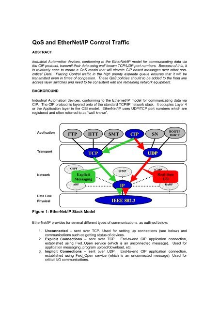
Industrial Automation devices, conforming to the Ethernet/<strong>IP</strong> model for communicating data via<br />
C<strong>IP</strong>. The C<strong>IP</strong> protocol is layered onto of the st<strong>and</strong>ard TCP/<strong>IP</strong> network stack. It occupies Layer 4<br />
or the Application layer in the OSI model. <strong>EtherNet</strong>/<strong>IP</strong> uses UDP/TCP port numbers which are<br />
registered <strong>and</strong> often referred to as “well known”.<br />
Application<br />
Transport<br />
Network<br />
Data Link<br />
Physical<br />
FTP HTT<br />
OSPF<br />
Explicit IGRP<br />
Messaging<br />
TCP<br />
Figure 1: <strong>EtherNet</strong>/<strong>IP</strong> Stack Model<br />
SMT C<strong>IP</strong> SN<br />
ICMP<br />
UDP<br />
IGMP<br />
ARP <strong>IP</strong> RARP<br />
IEEE 802.3<br />
<strong>EtherNet</strong>/<strong>IP</strong> provides for several different types of communications, as outlined below:<br />
BOOTP<br />
DHCP<br />
1. Unconnected – sent over TCP. Used for setting up connections (see below) <strong>and</strong><br />
communications such as getting status of devices.<br />
2. Explicit Connections – sent over TCP. End-to-end C<strong>IP</strong> application connection,<br />
established using Fwd_Open service (which is an unconnected message). Used for<br />
application messaging, program upload/download, etc.<br />
3. Implicit Connections – sent over UDP. End-to-end C<strong>IP</strong> application connection,<br />
established using Fwd_Open service (which is an unconnected message). Used for<br />
critical I/O communications.<br />
<strong>IP</strong><br />
Real-time<br />
I/O
The following port numbers are used as the Destination Port when a device sends <strong>EtherNet</strong>/<strong>IP</strong><br />
messages to another device:<br />
TCP port 44818 – used for Unconnected <strong>and</strong> Explicit messages<br />
UDP port 44818 – used for network browsing comm<strong>and</strong>s<br />
UDP port 2222 – used for Implicit messages<br />
The above ports may also be used as the Source Port. It is highly recommended that device<br />
vendors use the registered ports. However, depending on how a device has implemented<br />
<strong>EtherNet</strong>/<strong>IP</strong>, non-registered ports may be used. These ports are generally referred to as<br />
“ephemeral” ports. For more information on registered ports see the IANA website at:<br />
http://www.iana.org/assignments/port-numbers<br />
Quality of Service Overview<br />
It is very important in Factory networks to insure above traffic takes precedent over non critical<br />
traffic such as web browsing or file transfer. To priority traffic, Intelligent Ethernet networks use<br />
the Quality of Service (<strong>QoS</strong>) tags in the packet header. <strong>QoS</strong> can be marked in either the MAC<br />
layer (Layer 2) or the <strong>IP</strong> (Layer 3) header.<br />
For the Layer 2 header, this is referred as the Class of Service (CoS) bits. Three bits are used to<br />
identify 8 levels of service. The bits are carried in the 802.1q Trunk Headers along with the VLAN<br />
ID. When traffic crosses a Layer 2 boundary (i.e. going through a router), these bits may be<br />
converted to the Layer 3 values below <strong>and</strong> then remarked on the next Layer 2 segment.<br />
For Layer 3, they are called the Differentiated Services Code Point (DSCP) values. Six bits are<br />
used to identify 64 levels of service. Generally, the upper 3 bits are mapped to the three bits in<br />
the Layer 2 CoS tag <strong>and</strong> the lower three bits are used for more granular services.<br />
Once traffic has been marked (or classified), it can then be routed correctly. Consider the<br />
network to be a multilane highway. <strong>Traffic</strong> flows in each lane <strong>and</strong> different speeds <strong>and</strong> with<br />
different priority. This fine when the traffic on the highway is light. However, what happens when<br />
an ambulance or firetruck needs to make its way down a congested section of freeway. The<br />
same is true here, a mechanism must exist to elevate <strong>and</strong> insure that high priority traffic makes it<br />
way through the network, even if the network becomes congested.<br />
Typically, Intelligent Ethernet devices contain multiple output queues where each queue is<br />
assigned a certain priority level. By servicing the higher priority queues first, the important traffic<br />
gets transmitted first. This is done by mapping the <strong>QoS</strong> values to the particular queues.
<strong>QoS</strong> example using the Catalyst 2955 Industrial Ethernet Switch<br />
The Catalyst 2955 switch has four output queues. Each queue is linked to two CoS <strong>and</strong> 8 DSCP<br />
Values:<br />
Queue CoS Values DSCP Values<br />
1 0,1 0-15<br />
2 2,3 16-31<br />
3 4,5 32-47<br />
4 6,7 48-63<br />
CoS values 6 <strong>and</strong> 7 are generally reserved for network control messages. Therefore, the highest<br />
value for user data is CoS value 5 (DSCP value 40). In this example, the C<strong>IP</strong> traffic will be<br />
marked as CoS value 5.<br />
For C<strong>IP</strong> based messaging, Implicit messages using UDP port number 2222 have a higher<br />
importance than either the explicit or network browsing comm<strong>and</strong>s using TCP/UDP port number<br />
44818. In both cases, these messages should still have a higher priority over other network<br />
traffic. To accomplish this, two classifications need to be made using st<strong>and</strong>ard Cisco Access<br />
<strong>Control</strong> Lists (ACLs). Access list 101 will define the Implicit messages <strong>and</strong> access list 102 will<br />
define all other C<strong>IP</strong> based messages<br />
access-list 101 permit udp any any eq 2222<br />
access-list 102 permit udp any any eq 44818<br />
acesss-list 102 permit tcp any any eq 44818<br />
Once the ACLs are created, a policer needs to be created to match these ACL <strong>and</strong> mark the <strong>QoS</strong><br />
values to assign the appropriate priorities.<br />
class-map match-all C<strong>IP</strong>-IMPLICIT<br />
match access-group 101<br />
class-map match all C<strong>IP</strong>-Other<br />
match access-group<br />
policy-map C<strong>IP</strong>-<strong>Traffic</strong><br />
class C<strong>IP</strong>-IMPLICIT<br />
set ip dscp 40<br />
class C<strong>IP</strong>-Other<br />
set ip dscp 32<br />
The above set of comm<strong>and</strong>s tell the switch that any traffic that is matched by the ACL group 101,<br />
will have its priority value (DSCP value) set to 40 <strong>and</strong> traffic matched by ACL group 102 will have<br />
the value of 32. Since the switch will also map the Layer 3 DSCP value back to the Layer 2 CoS<br />
value, then that traffic will also have CoS value of 5. Lastly, the policer needs to be applied to all<br />
access ports that are connected to C<strong>IP</strong> based controllers. For each port, the follow comm<strong>and</strong><br />
needs to be added to the configuration.<br />
Summary<br />
service-policy input C<strong>IP</strong>-<strong>Traffic</strong><br />
Once these two policers have been created, all C<strong>IP</strong> traffic will be marked High Priority <strong>and</strong> will be<br />
transmitted throughout the network using the High Priority Queues. Implicit messaging will have<br />
the highest priority followed by the remaining C<strong>IP</strong> messages. All other traffic will remain at their<br />
existing priority levels. In this example, Implicit messages will get assigned to the highest priority
queue, other C<strong>IP</strong> messages to the next highest, <strong>and</strong> all remaining network traffic can use the two<br />
lower priority queues.<br />
Authors<br />
Kenneth Coley,<br />
Technical Marketing Engineer for Industrial Ethernet Products,<br />
Cisco Systems, Inc.<br />
Brian Batke,<br />
Senior Project Engineer for Embedded Software<br />
Rockwell Automation