Developer Recommendations White Paper - EtherNet/IP
Developer Recommendations White Paper - EtherNet/IP
Developer Recommendations White Paper - EtherNet/IP

You also want an ePaper? Increase the reach of your titles
YUMPU automatically turns print PDFs into web optimized ePapers that Google loves.
<strong>Developer</strong> <strong>Recommendations</strong><br />
<strong>White</strong> <strong>Paper</strong><br />
10 May 2001<br />
Revision 1.00<br />
Published by<br />
Open DeviceNet Vendor Association (ODVA)<br />
ControlNet International (CI)<br />
Industrial Ethernet Association (IEA)
<strong>EtherNet</strong>/<strong>IP</strong> <strong>Developer</strong> <strong>Recommendations</strong><br />
Document Revision Log<br />
Revision Sections Remarks Date Author<br />
1.00 Initial Release 5/10/01 Enabler JSIG<br />
Revision 1.00 i
<strong>EtherNet</strong>/<strong>IP</strong> <strong>Developer</strong> <strong>Recommendations</strong><br />
Table of Contents<br />
1. OVERVIEW.......................................................................................................................................... 1<br />
1.1. OVERVIEW OF TCP/<strong>IP</strong> ..................................................................................................................... 1<br />
1.2. OVERVIEW OF ETHERNET/<strong>IP</strong> ........................................................................................................... 3<br />
2. THE APPLICABILITY OF ETHERNET AND TCP/<strong>IP</strong> FOR INDUSTRIAL CONTROL.......... 5<br />
3. DIFFERENT LEVELS OF COMMUNICATION............................................................................. 6<br />
3.1. CATEGORIES OF CONTROL NETWORK MESSAGES............................................................................ 7<br />
3.1.1. Control Dialogs ...................................................................................................................... 7<br />
3.1.2. Information & Identification Dialogs ..................................................................................... 8<br />
3.1.3. Diagnostic & Configuration Dialogs...................................................................................... 8<br />
3.1.4. Summary ................................................................................................................................. 8<br />
3.2. QUALITY OF SERVICE RELATIONSH<strong>IP</strong>S............................................................................................. 9<br />
3.2.1. Determinism, Control & Fault Response Time Requirements .............................................. 10<br />
3.2.2. Determinism & Fault Response Time Requirement .............................................................. 11<br />
3.2.3. Control versus Information Dialogs ..................................................................................... 11<br />
3.2.4. How do we decide if Ethernet is the right network? ............................................................. 11<br />
4. RECOMMENDATIONS FOR PHYSICAL LAYER COMPONENTS......................................... 14<br />
4.1. CONTROLLER CH<strong>IP</strong>S....................................................................................................................... 14<br />
4.2. MAGNETICS ................................................................................................................................... 14<br />
4.3. PROTECTION CIRCUITRY................................................................................................................ 15<br />
4.4. CONNECTORS (JACKS AND PLUGS) ................................................................................................ 16<br />
4.5. CABLES.......................................................................................................................................... 16<br />
4.6. DEVICE DESIGN (PHYSICAL LAYER).............................................................................................. 17<br />
5. RECOMMENDATIONS FOR TCP/<strong>IP</strong> STACK.............................................................................. 20<br />
6. RECOMMENDATIONS FOR OPERATING SYSTEM ................................................................ 21<br />
7. ETHERNET/<strong>IP</strong> ENABLER TECHNOLOGY ................................................................................. 22<br />
7.1. PRE-COMPILED EXECUTABLES ....................................................................................................... 22<br />
7.1.1. V5 GUI executables .............................................................................................................. 22<br />
7.1.2. V5 Console executables ........................................................................................................ 22<br />
7.2. ETHERNET/<strong>IP</strong> LEVEL 2 EXAMPLE SOURCE CODE.......................................................................... 22<br />
7.3. DOCUMENTATION.......................................................................................................................... 23<br />
7.4. NETWORK PROTOCOL ANALYSIS TOOL ......................................................................................... 23<br />
8. ORGANIZATIONAL SUPPORT ..................................................................................................... 27<br />
APPENDIX.................................................................................................................................................. 28<br />
A. ETHERNET SWITCHES ........................................................................................................................ 28<br />
Revision 1.00 ii
1. Overview<br />
<strong>EtherNet</strong>/<strong>IP</strong> <strong>Developer</strong> <strong>Recommendations</strong><br />
Interest in networking continues to grow rapidly as more companies and industries move their products and<br />
services to the Internet. Within the office environment, Ethernet is the most popular medium for<br />
connecting computers to each other and the Internet. This growing interest has not been lost on the<br />
industrial communications industry. There have been increasing inquiries from vendors, OEMs and end<br />
users about using Ethernet as the communication network for factory floor control.<br />
For devices to converse and interoperate over Ethernet (or any network), a common application layer is<br />
needed. Although common protocols for file transfer (FTP), e-mail (SMTP), World Wide Web (HTTP)<br />
and others have been established for several applications, the situation is not so simple in the area of<br />
industrial automation. Each vendor of automation equipment that runs over Ethernet TCP/<strong>IP</strong> has<br />
implemented its own application layer. They each speak a different language. As a result, a standard<br />
application layer, common object models and universal device profiles don’t exist. Ethernet users are<br />
currently tied to proprietary solutions and aren’t able to benefit from the best-in-class and best-in-value<br />
options offered by an open market. <strong>EtherNet</strong>/<strong>IP</strong>, which is based on TCP/<strong>IP</strong> and UDP/<strong>IP</strong> protocols, fills<br />
the void by delivering interoperable Ethernet products. This is possible because <strong>EtherNet</strong>/<strong>IP</strong> uses a proven<br />
and open standard application layer. Independent <strong>EtherNet</strong>/<strong>IP</strong> conformance test labs are being established<br />
to promote conformance to the specification and verify multi-vendor interoperability.<br />
The benefits of bringing <strong>EtherNet</strong>/<strong>IP</strong> to the plant floor are reduced cost, ease of integration and the<br />
intriguing idea of building Internet features into factory automation equipment.<br />
This paper provides recommendations to vendors interested in developing <strong>EtherNet</strong>/<strong>IP</strong> products for the<br />
industrial control markets. The recommendations are intended to help vendors develop <strong>EtherNet</strong>/<strong>IP</strong><br />
products that best meet the needs of end users and to share experience from early adopters and <strong>EtherNet</strong>/<strong>IP</strong><br />
technology inventors.<br />
The Open DeviceNet Vendor Association (http://www.ODVA.org), ControlNet International<br />
(http://www.ControlNet.org) and the Industrial <strong>EtherNet</strong> Association (http://industrialethernet.com),<br />
recognizing the interest and potential of implementing existing fieldbus protocols on top of Ethernet. They<br />
have taken the joint initiative to identify best practices and methods for implementing the<br />
DeviceNet/ControlNet application layer protocols over a TCP/<strong>IP</strong> network. One of the results of this effort<br />
has been the development of <strong>EtherNet</strong>/<strong>IP</strong>, an industrial automation protocol based on C<strong>IP</strong> (Control and<br />
Information Protocol) which is used in both DeviceNet and ControlNet.. <strong>EtherNet</strong>/<strong>IP</strong> is defined as C<strong>IP</strong><br />
operating on top of the TCP/<strong>IP</strong> protocol suite over Ethernet. Another result of the initiative is the<br />
publication of papers to assist vendors and end users of in the development and use of <strong>EtherNet</strong>/<strong>IP</strong><br />
products.<br />
1.1. Overview of TCP/<strong>IP</strong><br />
TCP/<strong>IP</strong> stands for “Transmission Control Protocol / Internet Protocol”. As is normal within the Internet<br />
community, we will use “TCP/<strong>IP</strong>” to refer to the entire suite of internetworking protocols that provide the<br />
networking between machines and sub-networks and is the common language of the Internet and its<br />
applications. TCP/<strong>IP</strong> can operate over many different physical networks. This paper is concerned with<br />
TCP/<strong>IP</strong> operating over Ethernet. The protocols providing the foundation of a TCP/<strong>IP</strong> network are:<br />
• <strong>IP</strong> – (Internet Protocol) provides the means to transfer a packet of data from a source node to a<br />
destination node either within the same local network or to a distant network. <strong>IP</strong> also provides the<br />
means to transmit a packet of data to multiple destinations through the use of broadcast or<br />
multicast destination addresses.<br />
• ICMP – (Internet Control Message Protocol) provides the means to send control and diagnostic<br />
information between nodes on a network.<br />
Revision 1.00 1
<strong>EtherNet</strong>/<strong>IP</strong> <strong>Developer</strong> <strong>Recommendations</strong><br />
• IGMP – (Internet Group Multicast Protocol) provides support for the management of multicast<br />
groups within a TCP/<strong>IP</strong> network. A single message transmitted to a multicast destination address<br />
may be received by any number of destinations. IGMP is used by destination to join that address.<br />
Any node may belong to zero, one or more multicast groups depending on the capability of its<br />
TCP/<strong>IP</strong> stack and Ethernet chip/driver.<br />
• UDP – (User Datagram Protocol) provides best effort non-guaranteed delivery of data to an end<br />
point within a node. A UDP message requires less CPU overhead to process and route than would<br />
a TCP message.<br />
• TCP – (Transmission Control Protocol) provides connection-oriented transfer of data between<br />
exactly two end points. Unlike UDP, data transfers are verified by TCP. This verification<br />
requires more CPU overhead.<br />
There are many other protocols available within the TCP/<strong>IP</strong> suite. The ones listed here provide the<br />
foundation upon which <strong>EtherNet</strong>/<strong>IP</strong> is built. TCP/<strong>IP</strong>, like most network protocols, is referred to as a<br />
“stack”. You will read or hear references to “protocol stacks” or “layers” whenever network software is<br />
discussed. These words are used because the different protocols that comprise TCP/<strong>IP</strong> are organized as<br />
layers stacked on top of each other. <strong>IP</strong> is the foundation upon which ICMP, IGMP, UDP and TCP are<br />
stacked. Higher level protocols are stacked on top of UDP and TCP. A packet of data must pass through<br />
the intermediate layers of protocols in order to reach its final destination.<br />
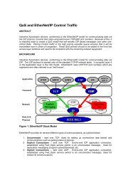
Figure 1 illustrates the stack concept. Notice how the Control and Information Protocol (C<strong>IP</strong>) straddles<br />
both UDP and TCP. Most high level protocols are stacked on top of either TCP or UDP. C<strong>IP</strong> uses both<br />
UDP and TCP for conveying implicit and explicit C<strong>IP</strong> messages. Explicit messages use TCP to pass one<br />
time messages and commands from one node to another. Implicit messages use UDP for control messages.<br />
Application and User<br />
Transport<br />
Network<br />
Data Link and Physical<br />
Message<br />
Router<br />
FTP HTTP<br />
OSPF<br />
IGRP<br />
Table<br />
Identity<br />
Revision 1.00 2<br />
DNS<br />
TCP UDP<br />
ICMP<br />
SNMP<br />
C<strong>IP</strong><br />
Input<br />
Point<br />
Input<br />
Assembly<br />
Output<br />
Point<br />
Output<br />
Assembly<br />
IGMP<br />
ARP <strong>IP</strong> RARP<br />
Any <strong>IP</strong> based network (i.e., Ethernet)<br />
Figure 1 - TCP/<strong>IP</strong> Stack<br />
BOOTP<br />
DHCP
1.2. Overview of <strong>EtherNet</strong>/<strong>IP</strong><br />
<strong>EtherNet</strong>/<strong>IP</strong> <strong>Developer</strong> <strong>Recommendations</strong><br />
<strong>EtherNet</strong>/<strong>IP</strong> stands for “Ethernet Industrial Protocol”. <strong>EtherNet</strong>/<strong>IP</strong> uses the same C<strong>IP</strong> (Control and<br />
Information Protocol) upper layers used by both DeviceNet and ControlNet. The lower layers of<br />
<strong>EtherNet</strong>/<strong>IP</strong> consist of TCP/<strong>IP</strong> combined with an “encapsulation layer” to provide the transport and<br />
network layer of the protocol and Ethernet as the data network and physical layer.<br />
Figure 2 illustrates the relationship between DeviceNet, ControlNet and <strong>EtherNet</strong>/<strong>IP</strong> layers. The<br />
Encapsulation layer uses both the TCP and UDP layers of the TCP/<strong>IP</strong> suite and provides the “glue” that<br />
allows C<strong>IP</strong> to be implemented transparently on top of Ethernet and TCP/<strong>IP</strong>. Besides encapsulating C<strong>IP</strong><br />
over TCP/UDP, the encapsulation protocol can encapsulate any other protocol, like Modbus, PROFIBUS,<br />
or Interbus. This provides a huge advantage for <strong>EtherNet</strong>/<strong>IP</strong> users. It allows every company to carry their<br />
legacy protocols over to the new <strong>EtherNet</strong>/<strong>IP</strong> technology.<br />
User<br />
Layer<br />
Application,<br />
Presentation<br />
and Session<br />
Layers<br />
Transport, Network,<br />
and Data Link<br />
Layers<br />
Physical<br />
Layer<br />
SEMI<br />
Devices<br />
DeviceNet<br />
Transport<br />
and DLL<br />
DeviceNet<br />
Physical<br />
Layer<br />
Pneum<br />
Valve<br />
Figure 2 - The Relationship between C<strong>IP</strong>, DeviceNet, ControlNet, and Ethernet/<strong>IP</strong> Layers<br />
Revision 1.00 3<br />
AC<br />
Drives<br />
Application Object Library<br />
C<strong>IP</strong> Application Layer<br />
Position<br />
Controllers<br />
Explicit & I/O Messaging, Routing<br />
ControlNet<br />
Transport<br />
and DLL<br />
ControlNet<br />
Physical<br />
Layer<br />
UDP<br />
Encapsulation<br />
<strong>IP</strong><br />
Other<br />
Profiles<br />
Ethernet DLL<br />
Ethernet<br />
Physical<br />
Layer<br />
TCP<br />
C<strong>IP</strong>
<strong>EtherNet</strong>/<strong>IP</strong> <strong>Developer</strong> <strong>Recommendations</strong><br />
The Open DeviceNet Vendor Association (ODVA) and ControlNet International (CI) have agreed to make<br />
the <strong>EtherNet</strong>/<strong>IP</strong> specification and Enabler technologies available free of charge. The Enabler Technologies<br />
consists of:<br />
• <strong>EtherNet</strong>/<strong>IP</strong> Level 2 Example Code (C source code and user manual)<br />
• Sample Windows ® NT client application with a graphical user interface (GUI)<br />
• Sample NT target (server) application with a GUI<br />
• <strong>EtherNet</strong>/<strong>IP</strong> traffic analyzer<br />
• <strong>EtherNet</strong>/<strong>IP</strong> Specification<br />
• <strong>White</strong> <strong>Paper</strong>s and Technical Documentation<br />
The Enabler technologies are posted on the <strong>EtherNet</strong>/<strong>IP</strong> web site at (http://www.Ethernet-<strong>IP</strong>.org). These<br />
technologies are also available from the CI and ODVA web sites. They are available for developers to<br />
download free of charge.<br />
Writing and debugging code is the most resource-consuming task for developers. With the <strong>EtherNet</strong>/<strong>IP</strong><br />
Level 2 Example Code and tools, developers have the foundation to create <strong>EtherNet</strong>/<strong>IP</strong> products with a<br />
very short time to market. Basically, all developers have to do is modify and customize the code based on<br />
the specific product need. This literally cuts hundreds of hours from the product-development cycle.<br />
ODVA and ControlNet International will support the adoption of <strong>EtherNet</strong>/<strong>IP</strong> by providing training classes,<br />
trade show presence, technical support, developer tools, speakers bureaus, white papers, and a conformance<br />
test suite.<br />
Revision 1.00 4
<strong>EtherNet</strong>/<strong>IP</strong> <strong>Developer</strong> <strong>Recommendations</strong><br />
2. The Applicability of Ethernet and TCP/<strong>IP</strong> for Industrial Control<br />
Using Ethernet in industrial control applications on the plant floor raises some questions about how this<br />
technology should be applied. Ethernet is already used in thousands of different applications in all kinds of<br />
industries. So using Ethernet on the plant floor is not necessarily new. The new part is to provide industry<br />
standard control functionality over the Ethernet wire. The questions of sufficient determinism for control<br />
applications and adequate industrial grade media options still remain.<br />
We will address the concerns regarding the use of Ethernet in an industrial control network and how<br />
suitable Ethernet is in terms of determinism and message frequency first.<br />
The use of Ethernet controller chips, wiring and switches that support full duplex operation will reduce or<br />
eliminate collisions on the network and permit a node to simultaneously transmit and receive messages<br />
effectively doubling data throughput. Implementing a full duplex network will increase hardware costs<br />
over that of a half duplex network, although it will definitely increase the level of determinism.<br />
Higher speed Ethernet standards such as 100 Mbps and 1,000 Mbps (gigabit) networks also help address<br />
concerns of determinism and performance by decreasing the probability of collisions and by reducing the<br />
time required to move a message from source to destination. However, moving to network speeds greater<br />
than 10 Mbps will increase your hardware costs.<br />
Another standard activity from the IEEE will also address the determinism issue. The IEEE 802.1p<br />
specification extends Ethernet functionality by providing, among other things, the means to assign priorities<br />
to messages on an Ethernet network. This will assure that the most important messages have priority when<br />
being sent, forwarded and received, provided control applications use the priority levels to differentiate<br />
between more important and less important messages. The next step would be to determine the priority<br />
levels for industrial applications. At present, the standard work is not completed. As soon as a general<br />
accepted prioritization level is available, ODVA and CI will adopt it and add it to the <strong>EtherNet</strong>/<strong>IP</strong><br />
specification.<br />
In regards to media issues, the physical layer of Ethernet was originally designed for the office<br />
environment. The currently available standards for Ethernet connectors and cabling are inadequate for<br />
some of the harsh conditions that can exist in industrial control environments. 100 Mbps Ethernet will<br />
introduce a complete new set of issues regarding media and noise susceptibility that needs to be addressed<br />
for the plant floor. The Physical Media Joint SIG of ODVA and CI are working on those issues and will<br />
provide a separate recommendation paper. Please check the <strong>EtherNet</strong>/<strong>IP</strong> web page.<br />
After having said all that, you see that care must be taken when defining industrial applications for Ethernet<br />
to ensure that the overall system provides the performance and the reliability needed for the level of control<br />
of any given application. Every network in the world has limits. There are limits to where Ethernet can be<br />
properly applied (e.g. intrinsically safe, safety networks, power on the wire, etc.). As Ethernet continues to<br />
evolve in the future, it may become suitable for increasingly demanding control applications.<br />
Revision 1.00 5
3. Different levels of Communication<br />
<strong>EtherNet</strong>/<strong>IP</strong> <strong>Developer</strong> <strong>Recommendations</strong><br />
Communications functionality required in the industrial control environment overlaps that of the office<br />
environment and adds some unique demands. Within a control system, the communication requirements<br />
vary depending upon the content of messages passed between nodes as well as the application being<br />
controlled. This section shall briefly describe three categories of messages conveyed over industrial control<br />
networks in attempt to in an attempt to describe the unique requirements of each.<br />
• Control (IO) messages<br />
• Diagnostic and configuration messages<br />
• Information and identification messages<br />
Control messages include the reading of inputs and writing of outputs. Diagnostic messages perform<br />
functions such as reading a detected fault value and silencing alarms. Configuration messages often occur<br />
while machines are running, to change gains and so forth, but are not performed as often as control<br />
messages. Lastly, information and identification messages occur on demand at intervals much greater than<br />
the other two message types. More specifically, consider that each message category has the following<br />
Quality of Service (QOS) characteristics:<br />
• Determinism<br />
• Percentage of nodes communicating every second<br />
• Response time<br />
• Fault detection to fault action time<br />
Later discussions will illustrate the relative importance of the Quality of Service criteria based upon the<br />
type of information being conveyed.<br />
All networks and communicating devices have a finite amount of bandwidth, where the amount of<br />
messages presented will eventually saturate the media or the CPU within the devices. When system<br />
tradeoffs are required, the relative importance of the various Quality of Service attributes shall be made<br />
using the following criteria.<br />
• Determinism<br />
In control networks, determinism is the ability to guarantee delivery of messages to the<br />
application within a specified period of time or else a fault action shall occur. The application<br />
being controlled will ideally determine the fault duration, although default values are generally<br />
used. Given a limited amount of network and CPU bandwidth, delivery of control messages (IO)<br />
takes precedence over all other message types since they affect the quality of the process being<br />
controlled. Determinism is less important for diagnostics and the least important for information<br />
dialogs.<br />
• Percentage of nodes communicating within an interval of time<br />
Consider a control network containing 50 nodes. In general, almost all of the nodes shall be<br />
producing and consuming control messages at a relatively short interval. Over a defined interval<br />
of time, the number of nodes producing diagnostic or configuration dialogs is generally less than<br />
five percent and may have bursts of up to ninety percent. The number of nodes producing<br />
information messages over the same interval will generally seldom exceed ten percent. When<br />
connecting a network monitor, control dialogs will generally dominate the network traffic.<br />
• Fault Response Time<br />
The time to detect a control fault and act on it is much shorter than the acceptable duration to<br />
detect a configuration dialog error, which is less duration than an information dialog error. For<br />
example, for control dialogs, detecting a faulted input node and taking a control action generally<br />
occurs within hundreds of milliseconds. The absolute value of the required duration is application<br />
Revision 1.00 6
<strong>EtherNet</strong>/<strong>IP</strong> <strong>Developer</strong> <strong>Recommendations</strong><br />
and machine dependent, but this value is a good rule of thumb. However, if an information upload<br />
fails, a machine or process failure does not generally occur. Bottom line, detecting the lack of the<br />
delivery of a control message and taking a control action is a very short interval relative to the<br />
other message types.<br />
• Control Response Time<br />
This criterion is listed last, since it is necessary, but not nearly sufficient to perform control over a<br />
network. Control response time is defined as the time it takes a sensor to detect a change in a<br />
machine or process state, to convey the new sensor value(s) to the control algorithm, to determine<br />
the desired action, and to effect a change in the related actuator(s). The sensor detection time,<br />
control algorithm time and actuation time are network-independent values. The network<br />
contributes the following delays:<br />
1. the time it takes from process detection to send the first bit of the input message on the wire<br />
(media access),<br />
2. the time it takes to convey the input message on the wire (wire time),<br />
3. the time it takes to deliver the new sensor value(s) to the control algorithm (stack execution),<br />
4. the time it takes to send the first bit of the output message on the wire (media access),<br />
5. the time it takes to convey the output message on the wire (wire time), and<br />
6. the time it takes to deliver the output value(s) to the actuator (stack execution).<br />
Failure to respond in the required interval may either damage the machine and/or process or result<br />
in less than desirable product quality. Generally, diagnostic and configuration dialogs are less<br />
critical, and information dialogs are the lowest priority.<br />
Although the control loop can be broken into infinitely finer granularity, this document shall focus<br />
on the prior general message categories and Quality of Service message behaviors.<br />
3.1. Categories of Control Network Messages<br />
Given the prior “Quality Of Service” overview, this section shall describe the same network messages,<br />
except provide additional details relative to typical message content. This is discussed since one<br />
application’s control dialogs may be another applications information dialogs.<br />
3.1.1. Control Dialogs<br />
Control dialogs involve the majority of nodes connected to a control network, where each node<br />
communicates control data at relatively short intervals of time, require relatively short response times,<br />
require relatively rapid indication of detected faults and results in relatively high levels of control<br />
determinism. These messages provide real time status about the machine or process being controlled and<br />
whose message values have direct impact on the quality of the end product being manufactured. If a<br />
typical control network were statistically monitored, over 90% of message traffic would be considered<br />
control dialogs. The content of control messages is usually fixed, data values are often directly applied to<br />
output points and actuators, and interpretation of message contents via typical “interpreted message<br />
protocols” generally does not exist. In effect, the meaning of each data bit within a given position within<br />
the control messages are usually predefined, only change if the system is reconfigured by a user, and<br />
therefore have significantly less CPU overhead to service than typical “interpreted messages”. See C<strong>IP</strong><br />
Assembly Object for details. C<strong>IP</strong> shall use the UPD/<strong>IP</strong> protocols to meet control dialog requirements since<br />
the “time to process the messages” is minimized due to the software layers that require interpretation are<br />
significantly less. Given the list of contributing response time delays previously discussed, control<br />
messages reduce all network and CPU delays to their absolute minimum possible for a given technology.<br />
Revision 1.00 7
<strong>EtherNet</strong>/<strong>IP</strong> <strong>Developer</strong> <strong>Recommendations</strong><br />
3.1.2. Information & Identification Dialogs<br />
Information and identification dialogs reside at the other Quality of Service extreme. At any point in time,<br />
these dialogs may involve a few nodes connected to a subnet, communicating over relatively long intervals<br />
of time, do not require short response times, do not require a rapid indication of detected faults and do not<br />
require high levels of determinism. Application programs can generally be written so that delayed delivery<br />
of these types of messages shall not negatively impact control dialog determinism.<br />
For example, a recipe that is conveyed to a batch metering system need only be delivered prior to its<br />
usage. Once the recipe is used, the actual amount of ingredients used in the current batch must be<br />
saved to an inventory control system. As long as the actual amounts are conveyed before the next<br />
batch is started the requirements are met. The intervals between these types of messages are generally<br />
measure in minutes. In fact, loss of this information during delivery, although highly undesirable, does<br />
not directly affect the quality of the product just manufactured. Additionally, the interval between a<br />
retry does not matter, as long as the information is not lost.<br />
Due to the non-deterministic and intermittent nature of these dialogs, as well as the widely varying content<br />
of these messages, existing TCP/<strong>IP</strong> protocols easily convey this category of messages.<br />
Similar behaviors are observed when identification dialogs interrogate nodes connected to a subnet. These<br />
dialogs often verify when the configuration of a control node has not changed, and if it has, control dialogs<br />
are inhibited until a human accepts configuration changes. Identification dialogs may also determine the<br />
types and amount of traffic a node is capable of producing, which may then be used to optionally limit the<br />
available bandwidth for supported messages. This bandwidth allocation may be accomplished using<br />
various techniques including system configuration rules, use of collision avoidance products, or even<br />
collision avoidance dialogs above the TCP/<strong>IP</strong> layers. However, identification dialogs are generally not<br />
time critical.<br />
Relative to this category of message dialogs, the existing TCP/<strong>IP</strong> protocols do NOT provide functionality<br />
to limit the rate at which messages presented to the subnet. C<strong>IP</strong>, when combined with the behavior of the<br />
applications initiating the production of these messages, may define techniques to inhibit information and<br />
identification messages from consuming the subnet bandwidth when deterministic control messages are<br />
pending. This message throttle is referred to as the production inhibit interval on other C<strong>IP</strong> networks.<br />
3.1.3. Diagnostic & Configuration Dialogs<br />
The diagnostic and configuration dialogs fill the void between control dialogs and information dialogs.<br />
These dialogs only occur when faults are detected or configurations are being altered during machine<br />
operation. When they occur, they generally don’t involve all the nodes on the subnet, the control actions<br />
have generally already occurred, and these dialogs are attempting to identify why a fault occurred to ideally<br />
prevent it in the future. The determinism required here, assuming fault actions are performed during the<br />
control dialogs, are of higher priority than information dialogs and lower priority than control dialogs. To<br />
the left side of center in Figure 3, these dialogs may be used for on-line editing, where control algorithms<br />
are being modified during program execution, where the Quality of Service requirements approach those of<br />
control dialogs. To the right of center, these dialogs may include configuration monitoring. Here again,<br />
existing Ethernet TCP/<strong>IP</strong> protocols and technology may be sufficient for the majority of these dialogs.<br />
3.1.4. Summary<br />
When building a control network, it is important to understand the relative importance of the various<br />
quality of service measurements have on the various types of messages. Summaries of the prior<br />
discussions are provided both textually in table form (Table 1) and graphically in Figure 3.<br />
Revision 1.00 8
<strong>EtherNet</strong>/<strong>IP</strong> <strong>Developer</strong> <strong>Recommendations</strong><br />
QUALITY OF<br />
MESSAGE CATEGORIES<br />
SERVICE Control Dialogs Diagnostic &<br />
Configuration Dialogs<br />
Information Dialogs<br />
Determinism Highly important Medium importance Low importance<br />
Percent of Nodes Majority (90%) nodes Few (5%) nodes send Few, if any, (1%) nodes<br />
Sending Messages send these messages these messages every send info messages<br />
every second<br />
every second<br />
second<br />
every second<br />
Fault Response Time Short interval (100’s Medium interval Long interval (seconds)<br />
msec) from faulted (second) from faulted from faulted information<br />
control message to fault diagnostic message or message to retry<br />
action<br />
retry<br />
Response Time Short interval (10’s Medium interval from Long interval from<br />
msec) from message receipt of message to receipt of message to<br />
receipt to action response message (100’s response message<br />
/response.<br />
msec)<br />
(seconds)<br />
Table 1 - Message Categories versus Quality Of Service<br />
The meaning of the vertical axis changes with each category of message and was described in the prior<br />
sections. The various plots are general relationships, the values of which are application specific, and are<br />
solely intended to provide a relative measurement in a control network.<br />
high<br />
low<br />
determinism<br />
% nodes sending<br />
Control Diagnostic/Configuration Information<br />
Dialogs Dialogs Dialogs<br />
Figure 3 - Message Categories versus Quality Of Service<br />
The sections that follow shall discuss the relationships between the message categories and the quality of<br />
service attributes. It is hoped that this perspective will facilitate the understanding of the various tradeoffs<br />
that were made to put “control on Ethernet”.<br />
3.2. Quality of Service Relationships<br />
It should be apparent that control networks historically were optimized to support the far-left side of the<br />
dialogs shown in Figure 3. Information networks historically were optimized to support the far right side.<br />
The middle portion of the figure was historically achieved with “point to point” protocols. Today the<br />
improved network and CPU implementation technologies are allowing the convergence of all the features<br />
onto the same network. DeviceNet, ControlNet, and <strong>EtherNet</strong>/<strong>IP</strong> are individual examples of this<br />
convergence. In effect, the requirements have changed little over the past twenty years. The only change<br />
has been the availability of affordable technologies to meet these requirements without custom<br />
implementations.<br />
As history shows, networks can be easily constructed by limiting the requirements to those that are easily<br />
achieved given a specified technology. <strong>EtherNet</strong>/<strong>IP</strong> has specified an available set of open technologies and<br />
Revision 1.00 9<br />
Fault response time<br />
Response time
<strong>EtherNet</strong>/<strong>IP</strong> <strong>Developer</strong> <strong>Recommendations</strong><br />
attempts to meet all existing set of requirements. As is always the case, attempts to achieve the far-left side<br />
of requirements shall have consequences on system configurations.<br />
3.2.1. Determinism, Control & Fault Response Time Requirements<br />
Determinism does NOT mean delivering control data at a repetitive interval. This is merely one historical<br />
and simple method of delivering data within a known interval, as well as detecting when it is NOT<br />
delivered within a known interval. Subnet determinism is the ability to maintain a minimum update time<br />
from a sensor change to the associated actuator action(s) sufficient to maintain acceptable control of the<br />
machine or process. Fault response time requires that if a node faults, and the control data is NOT<br />
delivered within the required control loop interval, a fault action occurs prior to the occurrence of a<br />
machine or process failure. Combining these two requirements into a constant update interval is a brute<br />
force, easily understood, and easily implemented solution to meet three requirements. This is the approach<br />
taken for various competitive Ethernet networks, and is an allowed configuration using <strong>EtherNet</strong>/<strong>IP</strong>.<br />
An ideal change of state control system would only convey data when it changed or prior to a fault action<br />
occurring at a consuming node. When the implementation technology has a limited “wire bandwidth”,<br />
health indications may be provided by sending null (zero data byte) messages if control data has not<br />
changed, or sending control data messages immediately upon detection of a relevant change. Receipt of a<br />
null control data message may not result in execution of the associated control algorithm and production of<br />
the resulting output message. Since Ethernet minimum packet sizes are so large, the only reason a null<br />
message would be sent would be to eliminate the CPU control algorithm execution time and associated<br />
control output message production when control data has not changed. Existing network standards, like the<br />
TCP/<strong>IP</strong> suite do not include this functionality within their scope of requirements. The common methods of<br />
achieving these requirements are among some of the items specified within <strong>EtherNet</strong>/<strong>IP</strong> and C<strong>IP</strong>.<br />
What types of control applications can be solved with the initial <strong>EtherNet</strong>/<strong>IP</strong> products? Very high speed<br />
control systems, like high speed coordinated motion may update each axis, and receive its current status<br />
once every two milliseconds. <strong>EtherNet</strong>/<strong>IP</strong> is not the current solution for these applications. However,<br />
typical machine tool applications may close loops on the order of once every ten to hundred milliseconds,<br />
and many process control applications may close loops once every second. The <strong>EtherNet</strong>/<strong>IP</strong> solution can<br />
solve most of these target applications. Just beware, an <strong>EtherNet</strong>/<strong>IP</strong> solution that works for one application<br />
may be totally unacceptable for another.<br />
It should also be noted that all requirements could be easily met if customers were willing to pay five<br />
hundred dollars for a communicating limit switch. However, low end networked control devices must be<br />
competitive with traditional devices connected to traditional IO modules. This is the primary reason why<br />
<strong>EtherNet</strong>/<strong>IP</strong> is not competitive with DeviceNet, but the sharing of application interfaces (C<strong>IP</strong>) on both<br />
subnets shall greatly simplify a customer’s integration and maintenance costs while enhancing system<br />
interoperability.<br />
From an implementation perspective, within many control devices, the processing of a control message<br />
shall preempt the processing of any of the other message categories. The application layer for control<br />
messages is often analogous to directly reading and writing memory locations, where output actions occur<br />
immediately upon writing the received value to memory. Bottom line, interpretation of message protocols<br />
is reduced to its lowest common denominator to minimize delays. Most commercially available TCP/<strong>IP</strong><br />
stacks do not provide expedient action of selected UDP/<strong>IP</strong> messages versus TCP/<strong>IP</strong> messages. This is a<br />
key differentiator of commercially available TCP/<strong>IP</strong> stacks.<br />
The existing TCP/<strong>IP</strong> stacks rely entirely on the Ethernet access mechanisms to detect collisions, back off,<br />
and retransmit messages. This often becomes a discussion topic relative to determinism. As discussed<br />
earlier, this only becomes an issue when fault actions occur due to lack of control message delivery after a<br />
defined interval of time. In many applications, like general process control, the fault actions’ duration is so<br />
large that this will rarely, if ever, become an issue.<br />
Revision 1.00 10
<strong>EtherNet</strong>/<strong>IP</strong> <strong>Developer</strong> <strong>Recommendations</strong><br />
A low rate of Ethernet packet collisions will allow a higher level of determinism. Some Ethernet protocols<br />
rely on low traffic density to minimize collisions, but they sacrifice determinism in their worst cases. A<br />
simple collision avoidance technique is used in many traditional master/slave “scanners”. Programmable<br />
controllers, present in many manufacturing plants today, employ a master/slave scanner to write and read<br />
I/O data. A single client controller sends output data to a node. The node replies with its input data. Upon<br />
receipt of the input response, the client controller sends output data to the next node in its scan list. This<br />
continues until all I/O nodes have been updated. The “polling” process repeats continuously while the<br />
controller is running. (Other collision avoidance techniques exist.) In a master/slave system, polled I/O<br />
nodes only speak when they are spoken to, and only one client resides on the subnet. The result is that<br />
collisions NEVER occur! Using this simple system configuration, subnet utilization is solely limited by the<br />
time it takes the I/O node to service the output message produced by the client controller and start<br />
producing its input response message.<br />
This type of system is totally deterministic, especially if the maximum delay that each I/O node may take to<br />
start its response can be determined. The “scan interval” is merely the sum of the update intervals of all the<br />
I/O nodes and generally includes some additional time for information and diagnostic dialogs after the I/O<br />
scan. Bottom line, techniques are available to solve all of the message delivery issues previously discussed<br />
as long as a customer limits the types of nodes connected to a subnet. The extremely simple master/slave<br />
solution does NOT allow more than one client on the control subnet, nor does it allow office type<br />
communications like surfing the web! A robust solution may provide methods of: identifying a new node,<br />
identifying when a node may participate on the physical medium, and enabling it’s a node’s<br />
communications assuming it meets the criteria established for a given machine application. <strong>EtherNet</strong>/<strong>IP</strong><br />
may specify various system behaviors and associated mechanisms as time goes on.<br />
3.2.2. Determinism & Fault Response Time Requirement<br />
When control dialogs cease, immediate local fault actions shall occur. This has nothing to do with the<br />
delivery of messages, but the timeliness under which non-delivery of a control message is detected and a<br />
fault action taken. Module health is actually a separate requirement from control data delivery, but both are<br />
very important in a control system. The fault intervals are generally two to three times the expected packet<br />
rate and the fault action almost always involves the objects consuming the control data. Since the<br />
production of a separate health message would only consume valuable subnet and CPU bandwidth,<br />
traditional implementations generally combine these requirements by monitoring the control data<br />
connection. Control message consumption intervals provided by TCP/<strong>IP</strong> stacks are much greater than<br />
intervals provided by UDP/<strong>IP</strong> stacks. C<strong>IP</strong> utilizes the efficiency of the UDP/<strong>IP</strong> protocol for control<br />
communication. C<strong>IP</strong> technologies define common interfaces to monitor module health and control data<br />
delivery.<br />
3.2.3. Control versus Information Dialogs<br />
As indicated, within a control system, the majority of nodes perform control dialogs on a relatively regular<br />
basis. Information messages occur even less often and with only a few nodes at any point in time.<br />
However, configuration dialogs generally only occur during initial system commissioning or during<br />
upgrades, and diagnostic dialogs only occur with faulted nodes and only when faults are detected. Stated<br />
differently, if nodes on a control subnet were allowed to speak at any time and convey very large amounts<br />
of data whenever they wanted, control dialogs may be preempted or even destroyed by collisions and fault<br />
actions shall occur. A users system configuration and associated application software will impact this<br />
behavior and is beyond the scope of this document.<br />
3.2.4. How do we decide if Ethernet is the right network?<br />
Where can Ethernet be applied today when the application contains the message categories described<br />
above? Referring to Table 1, it appears that existing Ethernet protocols and hardware may be suitable<br />
Revision 1.00 11
<strong>EtherNet</strong>/<strong>IP</strong> <strong>Developer</strong> <strong>Recommendations</strong><br />
within applications requiring all but control dialogs. The major contributing factors of interest in assessing<br />
any Ethernet based solution, including <strong>EtherNet</strong>/<strong>IP</strong> are:<br />
• The number of nodes per segment<br />
• The size of messages<br />
• The frequency of messages<br />
• Message traffic patterns<br />
• The events that trigger production of all messages<br />
• The tolerance of the application being controlled to delayed message delivery due to a congested<br />
network<br />
Considering the minimum message size of 64 bytes, a 10 Mbps Ethernet network can transfer a theoretical<br />
maximum of about 14,200 messages per second 1 . No known existing networks operate under these<br />
conditions and no known existing nodes are capable of accepting and/or rejecting one Ethernet message<br />
every sixty-seven (67) microseconds! As a “rule of thumb”, a shared (non-switched) Ethernet segment is<br />
congested and approaching excessive load when the load exceeds 20% of the network utilization. Network<br />
utilization refers to the percentage of time in which the network is busy carrying data 2 . Beyond this load,<br />
the number of collisions increase and control message determinism degrades. This reduces the maximum<br />
theoretical message rate to 2,800 per second, which is still quite good for the amount of data delivered in a<br />
UDP/<strong>IP</strong> packet.<br />
The numbers discussed in the prior paragraph are theoretical. No known control system today can maintain<br />
the theoretical maximum message rate of Ethernet. When physical constraints such as CPU speed,<br />
available memory, protocol stack overhead, operating system (if present) overhead and application<br />
processing overhead, the realistic maximum message rate is measured in the low hundreds per second. If<br />
the message size increases or the application must do more complicated processing of a message, the<br />
message rate may drop even further. Using a low cost hub configuration, the node CPUs shall be<br />
overwhelmed well before the available bandwidth of the network is saturated. This problem can often be<br />
resolved by properly segmenting the network via the use switched hubs.<br />
How suitable is Ethernet for control dialogs? Answering this question is when control engineers get<br />
nervous. If the guaranteed delivery of control messages is very frequent and extremely critical and the loss<br />
or delay of a single control message could result in damaged product, equipment or injured personnel,<br />
commercial Ethernet solutions should NOT be used. The open C<strong>IP</strong> solution, once complete, shall provide<br />
the technology and conformance testing necessary to achieve traditional control system requirements in<br />
various system configurations.<br />
In addition to the physical and data link layer technologies, <strong>EtherNet</strong>/<strong>IP</strong> provides a proven industrial<br />
application layer within C<strong>IP</strong>. C<strong>IP</strong> is based on an open, object oriented Producer/Consumer Communication<br />
Model, that is optimized for automation applications. Additionally, it contains a broad range of<br />
standardized application objects, enabling improved multi-vendor system interoperability. An open<br />
network protocol, without a common set of application interfaces and behaviors, can never approach the<br />
ease of integration of this type of approach.<br />
As should be apparent from the prior network loading discussion, when it comes to a network’s speed, baud<br />
rate is only one of the factors to consider. The network communication model used to exchange control<br />
data and information between devices actually has a significant impact on network functionality, which is<br />
especially important on an Ethernet network. All networks fall into one of two categories:<br />
Source/Destination or Producer/Consumer. The difference between the two can be best conveyed by a<br />
human analogy. Assume one needs to tell a room full of people the time of day. With source/destination,<br />
one person reads a clock and then proceeds to individually tell each person in the room the time. In<br />
1<br />
Source: Measured Capacity of an Ethernet: Myths and Reality, David R. Boggs, Jeffrey C. Mogul and Christopher A. Kent,<br />
September 1988, http://www.research.compaq.com/wrl/publications/abstracts/88.4.html<br />
2<br />
Source: Technical Report – Issues in LAN Switching and Migration from a shared LAN Environment, Rich Seifert, November<br />
1995, http://www.ots.utexas.edu/ethernet/pdf/techrept14.pdf<br />
Revision 1.00 12
<strong>EtherNet</strong>/<strong>IP</strong> <strong>Developer</strong> <strong>Recommendations</strong><br />
producer/consumer mode, the same person announces the time to everyone at once and everyone can<br />
consume it at the same time. In a Producer/Consumer environment, “identifiers” embedded into each<br />
message are used by the devices to determine which messages they should “consume.” Although the<br />
network model does not impact the rate at which data is transmitted, it does affect how efficiently the<br />
available bandwidth is used. It uses less bandwidth because a producer/consumer network transmits a<br />
piece of information only once. Less bandwidth equates to greater efficiency and overall speed.<br />
<strong>EtherNet</strong>/<strong>IP</strong>, ControlNet, DeviceNet, and Foundation Fieldbus are examples of networks based on the<br />
Producer/Consumer technology.<br />
Revision 1.00 13
<strong>EtherNet</strong>/<strong>IP</strong> <strong>Developer</strong> <strong>Recommendations</strong><br />
4. <strong>Recommendations</strong> for Physical Layer Components<br />
4.1. Controller Chips<br />
<strong>EtherNet</strong>/<strong>IP</strong> and other Ethernet based industrial protocols require physical layer features that enhance the<br />
determinism and reliability of communications. The heart of an Ethernet physical layer is the controller<br />
chip and its related transceiver and magnetic components. Some controllers contain the transceiver on-chip<br />
while others require external transceivers. The sponsors of this paper, ODVA, CI and IEA, have identified<br />
the following core list of features that would make controllers very attractive to developers of <strong>EtherNet</strong>/<strong>IP</strong><br />
products:<br />
• Resistant to industrial environments – temperature, humidity, vibration, etc.<br />
• Support full duplex communication.<br />
• Support 10 Mbps and 100 Mbps operation.<br />
• Support IEEE 802.1p packet prioritization with different transmit and receive queues for each<br />
priority level. During a receive operation, the controller hardware would inspect the packet<br />
priority field and transfer the received packet to the appropriate queue. Driver software would<br />
check the queues in descending order of priority, ensuring that important messages are not queued<br />
up behind less important messages. During a transmit operation, the controller hardware would<br />
take the next waiting packet in the highest priority non-empty queue and transmit it.<br />
• Ability to change the transmission characteristics on a packet by packet basis. Driver software<br />
would set a control field at the head of each packet before placing the packet into its transmit<br />
queue. The control field would contain information about how the controller should handle that<br />
packet for during transmission. The control information would be used to instruct the controller to<br />
limit the number of retries to attempt before aborting transmission. This would be used for high<br />
priority packets that cannot afford to be delayed by numerous retires. The industrial control<br />
application may need to know immediately if the packet was not transmitted in a timely fashion.<br />
The transmission control field could also be used to enable or disable the automatic appending of<br />
CRC to the end of the packet.<br />
• Strong support for multicast address filtering. Minimize CPU cycles needed to accept and reject<br />
multicast packets.<br />
• Support for receiving all packets (promiscuous mode). Useful for diagnostic and monitoring<br />
applications. Normal applications would disable this feature.<br />
• Ability to perform deeper packet filtering in hardware – allow packets to be accepted/reject based<br />
on network protocol, UDP destination port, TCP destination port, etc.<br />
Some of the above features, such as 10/100 Mbps and Full/Half Duplex have already been implemented by<br />
some manufacturers. The other features will probably evolve over time as industrial uses for Ethernet<br />
continue to grow and a substantial market develops for these features.<br />
4.2. Magnetics<br />
Magnetics play an important role in providing isolation for the device from the cable plant. Any one of the<br />
components in the network will set the entire network performance. In addition to isolation, the<br />
transformer must provide as high common mode rejection (CMR) as possible. Most transformers only<br />
supply 30 dB to 40 dB at 0-30 MHz. <strong>Developer</strong>s are strongly encouraged to use transformers with a<br />
minimum of 59 dB at 30 MHz. Pulse Engineering makes an example of this type of transformer (H1112<br />
and H1126.) One known drawback is the common mode chokes may cause problems for transceivers that<br />
perform auto-crossover wiring detection. Some transceivers will produce distorted signals when the<br />
common mode choke is on the transceiver side of the transformer.<br />
Revision 1.00 14
4.3. Protection Circuitry<br />
<strong>EtherNet</strong>/<strong>IP</strong> <strong>Developer</strong> <strong>Recommendations</strong><br />
Protection circuitry provides Electrostatic Discharge (ESD), Surge and Electrical Fast Transient (EFT)<br />
protection. The circuit must be designed in such a way to not cause an imbalance in the transmit and<br />
receive pairs. Once again, any imbalance in the network will directly impact the CMR noise performance<br />
of that network. The purpose of the protection circuitry is to clamp the differential voltages to within safe<br />
levels for the transceiver. In addition, there are some devices that can clamp the common mode noise<br />
within safe limits. It is recommended that these devices be placed in different places depending on the<br />
desired level of protection.<br />
• If there is a need to clamp common mode and differential mode noises, the clamp circuitry should<br />
be placed between the transformer and the transceiver. Reference Figure 4.<br />
• If there is a need to only clamp the differential voltages on the pairs, then the clamp circuitry can<br />
be placed between the connector and the transformer. Reference Figure 5.<br />
Ethernet 10/<br />
100<br />
Transmitter<br />
Harris<br />
V30MLA1812TX1884<br />
RX+<br />
75 Ohm<br />
75 Ohm<br />
Figure 4 - Differential and Common Mode Clamp Circuit<br />
Revision 1.00 15<br />
RX-<br />
Transient Protection<br />
SEMTECH LC03-6<br />
Harris<br />
V30MLA1812TX1884<br />
Magnetics<br />
60dB CMRR<br />
1nF<br />
Magnetics<br />
60dB CMRR<br />
Transient Protection<br />
SEMTECH LC03-6<br />
TX+<br />
TX-<br />
Ethernet 10/100<br />
Receiver
4.4. Connectors (Jacks and Plugs)<br />
<strong>EtherNet</strong>/<strong>IP</strong> <strong>Developer</strong> <strong>Recommendations</strong><br />
Figure 5 - Differential Mode Clamp<br />
RJ style connectors are virtually found on all unshielded twisted pair (UTP) Medium Attachment Units.<br />
Generally these connectors perform well in office environments. However, industrial environments present<br />
some challenges. The following performance parameters must be investigated before designing in a RJ-45<br />
connector.<br />
• Contacts must be designed to withstand the high vibration and shock found on the factory floor.<br />
This vibration is typically 2 to 10 Gs.<br />
• Temperature ranges from –10 to +85 degrees C. The plastics must be selected to withstand the<br />
high temperatures.<br />
• Gold contacts are required to prevent corrosion in caustic environments.<br />
• The gold and under-plating must be robust enough to survive vibration and repeated insertion and<br />
removals of the connectors.<br />
• Sealing for the connector. There may be several connectors introduced in the next few months<br />
that attempt to solve the sealing issues. Selecting connectors other than the RJ-45 (sealed or<br />
unsealed) puts the responsibility on the designer to make sure the connector meets the stringent<br />
fast Ethernet specifications from an electrical performance perspective.<br />
4.5. Cables<br />
Ethernet 10/<br />
100<br />
Transmitter<br />
Harris<br />
V30MLA1812TX1884<br />
RX+<br />
RX-<br />
Magnetics<br />
60dB CMRR<br />
Harris<br />
V30MLA1812TX1884<br />
Transient Protection<br />
SEMTECH SLVU2.8-4<br />
75 Ohm<br />
1nF<br />
Cable performance is the most important contributor to the overall performance the industrial Ethernet<br />
network. Placement of the cable in the system is equally as important. System and/or cable designers are<br />
strongly encouraged to consult the <strong>EtherNet</strong>/<strong>IP</strong> specification for selection and design of cables to be used in<br />
an industrial control application. The use of standard off the shelf cables may cause system malfunction or<br />
Revision 1.00 16<br />
Transient Protection<br />
SEMTECH SLVU2.8-4<br />
75 Ohm<br />
Magnetics<br />
60dB CMRR<br />
TX+<br />
TX-<br />
Ethernet 10/100<br />
Receiver
<strong>EtherNet</strong>/<strong>IP</strong> <strong>Developer</strong> <strong>Recommendations</strong><br />
degradation. For proper installation and grounding methods are described in the <strong>EtherNet</strong>/<strong>IP</strong> Installation<br />
Guide.<br />
4.6. Device Design (Physical Layer)<br />
The industrial environment requires changes in the design and selection of components used in an industrial<br />
communications module. The following are critical details to consider when designing an industrial<br />
communications module for Industrial <strong>EtherNet</strong>/<strong>IP</strong>:<br />
• Temperature/Humidity and Vibration<br />
Select components that will survive the temperature and humidity of the environment. For<br />
example, the magnetics must meet the attenuation specification over the extended temperature<br />
range.<br />
• Immunity to Radiated and Conducted Noise<br />
High CMR is the key to maximizing the systems immunity to noise. Hardware designs must<br />
assure that Network CMR is not degraded by poor layout or improper selection of components.<br />
Trace lengths between the connector, magnetics and transceiver should be equal in length.<br />
• Radiated Emissions<br />
Layouts should be optimized for isolation. All digital traces should be kept away from the<br />
physical layer and never should be placed over earth grounds. Likewise, traces from the network<br />
side of the transformer should never be routed into the digital areas of the design. Earth ground<br />
should never be placed under the digital or analog area of a design.<br />
• Grounding<br />
Grounding of the shield and protective devices is critical in surviving the high noise/voltage<br />
environmental tests. Further grounding of the shield in UTP cables is important from a system<br />
perspective. Ground loops in the shield will cause noise to be coupled into the communications<br />
pairs. The shield termination recommendations are covered later in this section. Shield<br />
termination practices are an integral part of the <strong>EtherNet</strong>/<strong>IP</strong> specification.<br />
• Isolation<br />
From a safety and reliability perspective, isolation from the network and device power supply is<br />
very important. Virtually all Ethernet transformers are only rated at 1500V. Most industrial<br />
testing requires a minimum of 2KV. There can be enough energy that crosses from the network<br />
side into the transceiver side of the transformer to cause failure and present a safety hazard. The<br />
routing of conductors and bypass capacitor placement in the design can impact the isolation.<br />
Placing a bypass capacitor between Earth ground and digital ground can couple noise to and from<br />
the logic section of your design and is not advisable.<br />
• Shield Termination<br />
There are two methods of terminating the shield. Both result in a single DC point of ground.<br />
Option 1<br />
Option 1 should only be used when connecting two commercially off the shelf devices (Switch<br />
and NIC) together in a network. Any connectivity device such as Hub, Switch or Router that uses<br />
shielded RJ-45 jacks, will have a direct connection to earth either through the power plug or<br />
separate ground lug. This ground connection provides the single point of ground and should not<br />
be defeated. The device end should be isolated by not terminating the shield in the RJ-45 plug.<br />
Figure 6 is an example of how the single point termination can be implemented in the patch cord.<br />
Revision 1.00 17
<strong>EtherNet</strong>/<strong>IP</strong> <strong>Developer</strong> <strong>Recommendations</strong><br />
Connector<br />
Switch<br />
Revision 1.00 18<br />
1<br />
2<br />
3<br />
4<br />
5<br />
6<br />
7<br />
8<br />
Null Cable<br />
1<br />
2<br />
3<br />
4<br />
5<br />
6<br />
7<br />
8<br />
Connector<br />
Device<br />
Shield is open at this end<br />
Figure 6 - Patch Cord Single Ground Connection<br />
Option 2<br />
Option 2 should be used in the design of all <strong>EtherNet</strong>/<strong>IP</strong> devices. This provides a single point DC<br />
ground at the connectivity device and an AC ground at the <strong>EtherNet</strong>/<strong>IP</strong> device. The shield is<br />
terminated at the <strong>EtherNet</strong>/<strong>IP</strong> device to earth ground through a parallel RC. The values of the<br />
termination circuit are .01uF/500V (min) capacitor and 1 meg Ohm ¼ watt resistor. To protect the<br />
capacitor, a MOV should be placed in parallel with the RC. The part number of the MOV is<br />
provided in Figure 7 and Figure 8 below.<br />
.01 uF<br />
500V<br />
Device<br />
Termination<br />
1Meg<br />
.01 uF<br />
500V<br />
RJ45<br />
Shield<br />
Harris<br />
V30MLA1812T<br />
X1884<br />
Figure 7 - System Grounding<br />
1Meg<br />
RJ45<br />
Shield<br />
Harris<br />
V30MLA1812T<br />
X1884<br />
Figure 8 - RC Circuit with Protection<br />
10/100 Mb<br />
Ethernet<br />
Switch
<strong>EtherNet</strong>/<strong>IP</strong> <strong>Developer</strong> <strong>Recommendations</strong><br />
• Layout<br />
Layout is critical for noise hardening. High frequency devices should be isolated from the<br />
physical layer area. Clock lines should be terminated and routed away from the physical layer<br />
area. Likewise, never route earth ground or physical layer traces into or over digital areas.<br />
The digital ground plane and power planes should not extend into the physical layer area.<br />
Figure 9 provides an example layout. Circuit traces between the RJ-45 and transformer and<br />
from the transformers should be treated as transmission lines. This requires that the<br />
characteristic impedance be matched and constant. Figure 10 provides a microstrip line<br />
impedance calculation.<br />
h=.062<br />
Power<br />
Planes<br />
PHY<br />
Chip<br />
Revision 1.00 19<br />
0.08"<br />
Earth<br />
Ground<br />
Figure 9 - Typical Layout<br />
w=.010<br />
s=.053<br />
er=2.7<br />
symmetrical coplanar strips<br />
s .053 h .062<br />
w .010<br />
ε r 2.7<br />
Z 0<br />
Figure 10 - Micro Strip Technique<br />
Optional<br />
0.01uF/500V<br />
1 M 1/4W<br />
RJ-45<br />
LED<br />
LED<br />
30. π<br />
εeff<br />
. K
5. <strong>Recommendations</strong> for TCP/<strong>IP</strong> Stack<br />
<strong>EtherNet</strong>/<strong>IP</strong> <strong>Developer</strong> <strong>Recommendations</strong><br />
The TCP/<strong>IP</strong> stack shall be compliant with all relevant IETF (Internet Engineering Task Force) standards.<br />
Some stack features are required while others are recommended. <strong>EtherNet</strong>/<strong>IP</strong> Specification, Volume 2,<br />
Chapter 9, Section 4 (“Requirements for TCP/<strong>IP</strong> support”) contains minimum requirements for a TCP/<strong>IP</strong><br />
stack in all <strong>EtherNet</strong>/<strong>IP</strong> devices. Stack requirements help ensure compatibility with TCP/<strong>IP</strong> stacks in other<br />
products. In addition to the <strong>EtherNet</strong>/<strong>IP</strong> specification, the stack recommendations outlined below, promote<br />
message processing speed and portability to other operating environments.<br />
<strong>Recommendations</strong> for All <strong>EtherNet</strong>/<strong>IP</strong> Devices:<br />
• Stack should be reentrant – support multiple threads of execution.<br />
• Stack should minimize the copying of data when passing a packet up or down through the layers<br />
of the stack. This feature is often called “zero copy”.<br />
• Stack should not be “tweaked” or modified so as to preclude any <strong>IP</strong> and/or any TCP header<br />
options<br />
• Stack should include TCP & UDP Echo Servers (Port 7).<br />
• Driver for controller chip should support multiple priority message queues for both transmission<br />
and receptions.<br />
• Stack should support priority when processing received messages up through the layers of the<br />
stack to the application.<br />
• Stack should support priority when processing messages to be transmitted down through layers of<br />
the stack to the driver and the controller chip.<br />
• Application Program Interface (API) should support standard socket oriented interface.<br />
• Stack should provide options that allow it to operate in a mode that is optimized for <strong>EtherNet</strong>/<strong>IP</strong>.<br />
When operating in this mode, the stack will minimize CPU cycles required to determine if a<br />
message is <strong>EtherNet</strong>/<strong>IP</strong>. For example, the stack may filter by protocol ID or UDP/TCP port<br />
number before performing checksums.<br />
Requirements for implementing products using the <strong>EtherNet</strong>/<strong>IP</strong> Level 2 Example Code in a server:<br />
• Stack shall be reentrant – support multiple threads of execution.<br />
• Application Program Interface (API) shall support standard socket oriented interface.<br />
<strong>Recommendations</strong> for <strong>EtherNet</strong>/<strong>IP</strong> Clients (Connection Originators):<br />
• Stack should support <strong>IP</strong> Multicast reception.<br />
Revision 1.00 20
<strong>EtherNet</strong>/<strong>IP</strong> <strong>Developer</strong> <strong>Recommendations</strong><br />
6. <strong>Recommendations</strong> for Operating System<br />
<strong>Recommendations</strong> for all <strong>EtherNet</strong>/<strong>IP</strong> Devices:<br />
• Operating system (OS) should be real-time multitasking with support for preemptive task<br />
switching, task priorities, and round robin scheduling for tasks sharing the same priority.<br />
• OS should have published timings for different operations within well-defined reference<br />
environments. Operations of interest include task context switch, interrupt latency, get semaphore<br />
(or equivalent), set semaphore (or equivalent), inter-task communication (send and receive<br />
messages), memory management (allocate and free) and exception condition handling.<br />
Information about the reference environment includes CPU, clock speed, memory size, memory<br />
type (DRAM, SRAM, etc.), mode of CPU operation (protected mode, real mode, etc.).<br />
• OS should provide fixed block size memory management in addition to variable size management.<br />
Managing fixed block sizes is more efficient and is useful in message based applications such as<br />
<strong>EtherNet</strong>/<strong>IP</strong>.<br />
• OS should provide the means to monitor run-time operation during development so that<br />
developers may analyze their application. <strong>Developer</strong>s will want to be able to see CPU idle time,<br />
distribution of CPU time over the different application tasks, memory usage and interrupt<br />
performance. The monitor should be capable of being removed or disabled for the final<br />
application build.<br />
Requirements for implementing products using the <strong>EtherNet</strong>/<strong>IP</strong> Level 2 Example Code in a server:<br />
• OS shall support at least 20 tasks for <strong>EtherNet</strong>/<strong>IP</strong> in addition to tasks needed for other<br />
applications.<br />
• OS shall provide multiple queues and semaphores.<br />
• OS shall support dynamic task creation and deletion.<br />
• OS shall support dynamic memory allocation and release.<br />
Revision 1.00 21
7. <strong>EtherNet</strong>/<strong>IP</strong> Enabler Technology<br />
<strong>EtherNet</strong>/<strong>IP</strong> <strong>Developer</strong> <strong>Recommendations</strong><br />
This section provides an overview of enablers that are available for developers wishing to incorporate<br />
Ethernet/<strong>IP</strong> technology into their products.<br />
The Enablers include:<br />
• Pre-compiled executables for Windows NT/2000<br />
• Source code<br />
• Documentation<br />
• Network protocol analysis tool<br />
These enablers are available for download from the Ethernet/<strong>IP</strong> web page. Development teams may take<br />
advantage of these resources to significantly accelerate the product development cycle.<br />
7.1. Pre-compiled executables<br />
The Windows NT/2000 executables can serve as a starting point for understanding and implementing<br />
Ethernet/<strong>IP</strong> technology. When run simultaneously with the free C<strong>IP</strong>Alyzr network analysis tool,<br />
developers are able to observe and analyze the “on-the-wire” features of the protocol.<br />
There are two types of executables available, one a console application and the other a Windows GUI<br />
application.<br />
7.1.1. V5 GUI executables<br />
The V5 GUI executables consists of two WinNT/2000 GUI applications, along with a companion DLL,<br />
that comprise a demonstration of Ethernet/<strong>IP</strong>. The server is named V5_INOUT_SERVER_GUI.EXE. The<br />
client is named V5_INOUT_CLIENT.EXE, and the DLL is named ETHERNET<strong>IP</strong>NODE.DLL All files,<br />
including the DLL, are contained in V5_INOUT_EXE.Z<strong>IP</strong>.<br />
The client and server can be run locally on the same machine or across a network on two separate<br />
machines. In either case, note that a configuration file called <strong>IP</strong>_ADDR.TXT is used by the client to<br />
acquire the <strong>IP</strong> address of the machine where the server is running. This file must be edited at Line 3 with<br />
the proper <strong>IP</strong> address of the machine where the server is running (if the client and the server are both<br />
running locally on the same machine, the built-in TCP/<strong>IP</strong> loop-back address 127.0.0.1 can be used).<br />
7.1.2. V5 Console executables<br />
The V5 Console executables consists of a console-based client-server pair (each of these programs runs in a<br />
“DOS box” under WinNT/2000).<br />
The files are located in V5_CONSOLE_EXE.Z<strong>IP</strong>. Be sure to consult V5_CONSOLE_README.TXT for<br />
instructions on running these programs, and note that there is no configuration program necessary (the<br />
server <strong>IP</strong> address is passed on the command line to the client). As above, the executables can be run locally<br />
or between two different machines on a network.<br />
7.2. <strong>EtherNet</strong>/<strong>IP</strong> Level 2 Example Source Code<br />
Example source code is available for Level 1/Level 2 server/target devices. (Refer to the Ethernet/<strong>IP</strong><br />
Example Code Reference Guide for descriptions of the <strong>EtherNet</strong>/<strong>IP</strong> product model) As distributed, the<br />
example code can be used to build the Win32 server executables described above.<br />
Revision 1.00 22
<strong>EtherNet</strong>/<strong>IP</strong> <strong>Developer</strong> <strong>Recommendations</strong><br />
There are conditional compilation directives in some of the header files, which apply to the VxWorks port.<br />
For code porters, the #defines will be useful in compiling the server code for new platforms.<br />
The source code is contained in V5_CONSOLE_SRC.Z<strong>IP</strong>, V5_INOUT_SERVER_DLL.Z<strong>IP</strong>, and<br />
V5_INOUT_SERVER_GUI_SRC.Z<strong>IP</strong>. Each Z<strong>IP</strong> file contains a Microsoft DevStudio project file for use<br />
with Visual C++ 6.0.<br />
General configuration for controlling compilation is located in AB_CFG.H and AB_ENV.H.<br />
C<strong>IP</strong> object definition as used for the Ethernet/<strong>IP</strong> test code is switched on by the “#define<br />
CORE_OBJECTS” in AB_ENV.H. This #define invokes code to construct the following objects:<br />
C<strong>IP</strong> Object Class ID Source Files<br />
Identity Object 0x01 ID_OBJ.H ID_OBJ.C<br />
Message Router Object 0x02 MR_ROUTR.H MR_ROUTR.C<br />
Assembly Object 0x04 SY.H SY_OBJ.H SY_OBJ.C<br />
Connection Mgr Object 0x06 CM.H CM_TARGET.H<br />
CM_TARGET.C<br />
Unconnected Message Mgr UM.H UM_UTIL.H UM_UTIL.C<br />
7.3. Documentation<br />
The primary source for information on Ethernet/<strong>IP</strong> is the specification. The specification can be<br />
downloaded from the <strong>EtherNet</strong>/<strong>IP</strong> web page. The specification is a series of .PDF files. You will need an<br />
Acrobat PDF viewer to browse or print these; if you do not already have it installed on your system, go to<br />
http://www.adobe.com/products/acrobat/readstep.html to download a free copy.<br />
Secondary information sources are available from http://odva.org/10_2/10_fp_links.htm. The available files<br />
include several PowerPoint presentations (suffix is .PPT).<br />
The PowerPoint presentation files are:<br />
Dev Forum ppt.zip<br />
Application Interface Integration.zip<br />
C<strong>IP</strong> over Ethernet Demo.zip<br />
<strong>EtherNet</strong>/<strong>IP</strong><strong>Developer</strong> Forum Agenda.zip<br />
<strong>EtherNet</strong>/<strong>IP</strong><strong>Developer</strong> Forum Recap.zip<br />
<strong>EtherNet</strong>/<strong>IP</strong>Level 2 Example Code.zip<br />
<strong>IP</strong> Network Configuration.zip<br />
If you do not have PowerPoint installed on your computer, a viewer can be downloaded from<br />
http://download.cnet.com/downloads/0-10022-100-872821.html<br />
Another useful resource for new Ethernet/<strong>IP</strong> developers is the Ethernet/<strong>IP</strong> Example Code Reference Guide<br />
mentioned above. This is a compiled Windows help file archived in EN<strong>IP</strong>.zip. After unzipping to a<br />
temporary directory, run the SETUP.EXE to install locally on your computer.<br />
7.4. Network Protocol Analysis Tool<br />
The C<strong>IP</strong>Alyzr network analysis tool is available in a free, evaluation version, which is available at the<br />
Ethernet/<strong>IP</strong> web page. The free version captures 100 packets per run, while the commercial version has no<br />
limitations. The program runs on Win98/NT/2000 and does not require any special network drivers.<br />
Revision 1.00 23
<strong>EtherNet</strong>/<strong>IP</strong> <strong>Developer</strong> <strong>Recommendations</strong><br />
Both C<strong>IP</strong>Alyzr versions have capabilities over and above conventional Ethernet sniffers in that there are<br />
built-in functions to decode and display many standard industrial Ethernet protocols, including <strong>EtherNet</strong>/<strong>IP</strong>.<br />
Such a tool is invaluable for the developer who is trying to bring up the <strong>EtherNet</strong>/<strong>IP</strong> Enablers code on a<br />
new platform, or troubleshooting an existing installation.<br />
One of the convenient features of the tool is multiple viewpoints of the same set of Ethernet packets. For<br />
instance, in Figure 11 shown below, the “UDP” button is selected. This causes the application to show all<br />
the UDP packets present in the buffer. (Note that the first UDP packet in this view is #1051).<br />
Figure 11 – C<strong>IP</strong>Alyzr UDP Packet View<br />
Revision 1.00 24
<strong>EtherNet</strong>/<strong>IP</strong> <strong>Developer</strong> <strong>Recommendations</strong><br />
A great deal of packet data is displayed making it difficult to interpret. If the C<strong>IP</strong>-IO button is selected, the<br />
UDP packets, which are also IO packets under Ethernet/<strong>IP</strong>, are re-interpreted with the C<strong>IP</strong> fields<br />
displayed—again, starting with packet #1051. The displayed information becomes much more useful for<br />
the developer. See Figure 12 shown below.<br />
Figure 12 – C<strong>IP</strong>Alyzr C<strong>IP</strong> Packet View<br />
Revision 1.00 25
<strong>EtherNet</strong>/<strong>IP</strong> <strong>Developer</strong> <strong>Recommendations</strong><br />
The above <strong>EtherNet</strong>/<strong>IP</strong> capture represents the V5_INOUT_CLIENT sample application talking to<br />
V5_INOUT_SERVER_GUI. A snapshot of the actual <strong>EtherNet</strong>/<strong>IP</strong> data on the wire will be extremely<br />
useful, and the multiple views remove much of the tedium involved with manually decoding the protocols.<br />
See Figure 13 shown below.<br />
Figure 13 – C<strong>IP</strong>Alyzr E<strong>IP</strong> Packet Capture View<br />
Revision 1.00 26
8. Organizational Support<br />
<strong>EtherNet</strong>/<strong>IP</strong> <strong>Developer</strong> <strong>Recommendations</strong><br />
CI and ODVA will co-manage the <strong>EtherNet</strong>/<strong>IP</strong> specification including all enhancements. Joint Special<br />
Interest Groups (JSIG) comprised of CI and ODVA members were formed to develop and manage other<br />
aspects of <strong>EtherNet</strong>/<strong>IP</strong> technology including <strong>EtherNet</strong>/<strong>IP</strong> conformance tests, enabler products and end-user<br />
educational materials.<br />
Table 2 lists the current <strong>EtherNet</strong>/<strong>IP</strong> JSIGS and their responsibilities:<br />
Joint Special Interest Group JSIG Mission<br />
C<strong>IP</strong> Common System Architecture Develops and maintains technology common to<br />
<strong>EtherNet</strong>/<strong>IP</strong>, DeviceNet, and ControlNet<br />
<strong>EtherNet</strong>/<strong>IP</strong> Conformance Promotes uniform interpretation of specifications and<br />
verify product coexistence in evolving multi-vendor<br />
information and/or control systems by developing and<br />
deploying conformance test methods and test labs<br />
<strong>EtherNet</strong>/<strong>IP</strong> Enablers Promote the acceptance of the <strong>EtherNet</strong>/<strong>IP</strong> technology by<br />
providing assistance (in the form of enablers) to vendors<br />
developing <strong>EtherNet</strong>/<strong>IP</strong> products<br />
<strong>EtherNet</strong>/<strong>IP</strong> Physical Layer Develops and maintain specifications for Physical Layer<br />
components for use in Industrial <strong>EtherNet</strong>/<strong>IP</strong> applications<br />
<strong>EtherNet</strong>/<strong>IP</strong> System Develops and maintains technology specific to <strong>EtherNet</strong>/<strong>IP</strong><br />
<strong>EtherNet</strong>/<strong>IP</strong> Marketing –User<br />
Education<br />
Revision 1.00 27<br />
Develops and publishes information to assist the<br />
automation community in the evaluation, selection,<br />
specification and installation of Ethernet-based control<br />
systems<br />
Table 2 – <strong>EtherNet</strong>/<strong>IP</strong> JSIGs<br />
CI, IEA and ODVA will also provide <strong>EtherNet</strong>/<strong>IP</strong> technical support service as well as training for<br />
developers and product managers.<br />
ODVA is an independent organization of users, vendors, and distributors to support the worldwide growth<br />
of DeviceNet by assisting with tools, training, compliance testing and marketing activities. ODVA<br />
operates globally with offices in Europe, North America and Australia and affiliates in Japan, Korea, New<br />
Zealand and the United Kingdom. DeviceNet is an open communications network designed to connect<br />
factory floor devices, such as sensors, push buttons, motor starters and drives, to control systems.<br />
ControlNet International is an independent organization for users and vendors of ControlNet products.<br />
ControlNet is a real-time, control-layer network providing for high-speed transport of both time-critical I/O<br />
and messaging data, including upload/download of programming and configuration data and peer-to-peer<br />
messaging on a single or redundant, intrinsically safe physical media link. Deterministic and repeatable,<br />
ControlNet’s high-speed control and data capabilities significantly enhance I/O performance and peer-topeer<br />
communications.
A. Ethernet Switches<br />
<strong>EtherNet</strong>/<strong>IP</strong> <strong>Developer</strong> <strong>Recommendations</strong><br />
Appendix<br />
When selecting an Ethernet network device for implementation of <strong>EtherNet</strong>/<strong>IP</strong>, there are criteria that<br />
should be adhered to. It is important to determine what type of data to be transferred and what type of<br />
device to support the data requirements.<br />
It is recommended that when implementing Ethernet for process control, that an Ethernet Switching<br />
Hub or a “switch” be used. It is not a recommendation to implement Ethernet hubs for peer to peer or<br />
process control. There are multiple reasons for not utilizing this technology. The primary reason is<br />
hub technology utilizes shared bandwidth.<br />
Hub technology utilizes a shared medium, or shared bandwidth. This does not prevent messages from<br />
being heard by all others devices in a network, regardless whether the data is intended for them. This<br />
leads to unnecessary traffic on the network.<br />
Switching utilizes dedicated bandwidth allowing data to be sent directly to the intended device. This<br />
prevents any unnecessary traffic from being propagated throughout the network, thus reducing<br />
collisions. Implementing full duplex operation and prioritization can further enhance network<br />
performance.<br />
Ethernet in its original form is only half-duplex. This means a device can only transmit (talk) or<br />
receive (listen.) Therefore, a collision could occur at any time as all devices have common access to<br />
the medium. Even in a half-duplex switched environment a collision could occur. A frame of data<br />
could be sent from a device to the switch at the same time that the switch is forwarding a frame of data<br />
to the device. Full-duplex allows simultaneous transmit and receive (talk and listen) therefore<br />
eliminating the possibility of a collision.<br />
Ethernet also traditionally had no method for ensuring Quality of Service or setting priorities.<br />
Therefore switching should comply with the IEEE 802.1Q/p standard that supports prioritization of<br />
data packets. It should be noted that when a priority is set on a packet in the tag field, the originating<br />
device sets the priority.<br />
When selecting an Ethernet switch for process control, the following are some features that are<br />
recommended:<br />
• Support expanded temperature ranges if not in a controlled environment<br />
• Support expanded humidity rating if area is not temperature controlled<br />
• Support IEEE 802.1p<br />
• VLAN support<br />
• Simple Network Management Protocol (SNMP)<br />
• Contain WWW interface for web management<br />
• Employ some type of redundancy for network links<br />
• Support dual or alternate power inputs<br />
• Support autopartitioning (shuts down ports if excessive broadcasts are sensed)<br />
• Support full-duplex communication between all ports<br />
• Ability to switch one or more ports into promiscuous mode – all traffic from all other ports is<br />
copied to promiscuous ports. Monitoring and diagnostic equipment would be connected to<br />
this port for network monitoring.<br />
Revision 1.00 28