
You also want an ePaper? Increase the reach of your titles
YUMPU automatically turns print PDFs into web optimized ePapers that Google loves.
HIn3637<br />
VLF Magnetic Field Meter<br />
User's <strong>Manual</strong><br />
Copyright © 1993 by Holaday Industries, Inc.<br />
<strong>Manual</strong> #600055 2/00 $12.50
Revision Record<br />
<strong>Manual</strong> #600055<br />
HIn3637 VLF Meter<br />
Revision Description Date<br />
--- Release 9/93<br />
A Rev. Spec 4/94<br />
B Added CE Label 10/97<br />
C Update Recorder Output Level 01/00<br />
D Changed Area Code 2/00
TABLE OF CONTENTS<br />
1.0 DESCRIPTION ..................... 1<br />
Introduction ........................ 1<br />
2.0 SPECIFICATIONS ................... 3<br />
3.0 ACCEPTANCE AND CONTROLS ......... 7<br />
Introduction ....................... 7<br />
Unpacking and Acceptance ............ 7<br />
Battery .......................... 7<br />
Battery Charger .................... 7<br />
Controls, Indicators and Connectors ...... 9<br />
Recorder Output ................... 10<br />
Low Battery Indication ............... 11<br />
4.0 BATTERY CHARGING ............... 13<br />
Introduction ...................... 13<br />
Battery Tips ...................... 13<br />
Charging Procedure ................. 14<br />
Charging Considerations ............. 14<br />
Battery Replacement ................ 15<br />
5.0 MAINTENANCE ................... 17<br />
Introduction ...................... 17<br />
Maintenance Recommendations ........ 17<br />
Return Procedures .................. 17<br />
Periodic/Preventive Maintenance ........ 18<br />
Parts Information .................. 19<br />
6.0 MAKING MEASUREMENTS ........... 21<br />
Quick Start ...................... 21<br />
Description ...................... 22
7.0 THEORY OF OPERATION ............. 23<br />
Introduction ...................... 23<br />
Probe .......................... 23<br />
Range Select ..................... 23<br />
Pre-filter Section ................... 23<br />
Integrator Section .................. 25<br />
Post-filter Section .................. 25<br />
RMS Calculation ................... 25<br />
Power supply ..................... 25<br />
8.0 CALIBRATION .................... 27<br />
9.0 REFERENCES ..................... 29<br />
APPENDIX A<br />
VIDEO DISPLAY TERMINALS (VDTs) ......... 31<br />
VDT CHARACTERISTICS .............. 31<br />
General Description .............. 31<br />
Principles of Operation ............ 31<br />
Modulated DC Fields ............ 32<br />
60/50 Hz Fields ............... 33<br />
Deflection System Fields ......... 33<br />
Broadband RF Fields ............ 34<br />
CHARACTERIZING VDT EMISSIONS AND<br />
OPERATOR EXPOSURE .......... 35<br />
Introduction .................. 35<br />
Characterizing VDT Emissions ...... 35<br />
GUIDELINES FOR RF EXPOSURE ........ 37
Limited Warranty<br />
Holaday Industries, Inc. warrants each model HIn3637 3-<br />
Axis VLF Magnetic Field Meter to be free from defects in<br />
material and workmanship for a period of one year from<br />
the date of shipment to the purchaser. This warranty<br />
extends to the original purchaser only, and does not apply<br />
to the batteries or to any products or parts subject to<br />
misuse, neglect, accident, unauthorized service or<br />
abnormal conditions of operation.<br />
In the event an instrument covered by this warranty fails,<br />
Holaday Industries, Inc. will, without charge, repair and<br />
recalibrate the instrument if returned to their factory<br />
within one year of the original purchase—provided that<br />
Holaday Industries' examination discloses, to its<br />
satisfaction, that the product is defective. Holaday<br />
Industries, Inc., may, at its option, replace the product in<br />
lieu of repair. If the defect was caused by misuse,<br />
neglect, accident, unauthorized service or abnormal<br />
conditions of operation, repairs will be billed at a nominal<br />
cost. In such cases, an estimate will be provided before<br />
work is started, if requested by the purchaser.<br />
For warranty service, contact Holaday Industries, Inc.<br />
Provide the serial number of the instrument and complete<br />
details regarding the failure mode. You will then be given<br />
either service information or shipping instructions. Return<br />
the instrument to the factory, transportation prepaid.<br />
Repairs will be made at the factory and the instrument<br />
will be returned to you, transportation prepaid. Holaday<br />
Industries, Inc., assumes no responsibility for loss of, or<br />
damage to, products in transit.<br />
Warning!<br />
EXTREME CAUTION IS ADVISED WHEN WORKING IN<br />
ENVIRONMENTS WHERE CONTACT WITH HIGH VOLTAGE OR HIGH<br />
CURRENT CIRCUITS OR APPARATUS IS POSSIBLE. THIS IS<br />
PARTICULARLY TRUE WHEN ATTEMPTING TO OBTAIN ELECTRIC OR<br />
MAGNETIC FIELD STRENGTH MEASUREMENTS IN CONFINED<br />
QUARTERS SUCH AS INSIDE CABIN<strong>ETS</strong> CONTAINING ELECTRICALLY<br />
OPERATED EQUIPMENT, ELECTRIC POWER SUBSTATIONS OR IN<br />
VERY CLOSE PROXIMITY TO THE CONDUCTORS OF ENERGIZED<br />
POWER LINES. ACCIDENTAL CONTACT WITH OBJECTS OR<br />
CIRCUITS OPERATED AT HIGH VOLTAGES OR HIGH CURRENTS CAN<br />
BE LETHAL! HOLADAY INDUSTRIES, INC. ASSUMES NO LIABILITY
HIn3637 <strong>Manual</strong> Page — 1<br />
1.0 DESCRIPTION<br />
Introduction<br />
The HIn3637 VLF (very-low frequency) Magnetic Field<br />
Meter measures magnetic field flux density in the<br />
frequency range of 2 kHz to 400 kHz. The capabilities of<br />
this instrument are designed to conform to the guidelines<br />
issued recently in Sweden—as well as the IEEE P-1140<br />
protocol—for measuring VLF magnetic fields produced by<br />
video display terminals (VDTs). Applications for this<br />
versatile meter range from VDTs and computer monitors<br />
to high current factory locations.<br />
The HIn3637 is a self-contained three-axis flux density<br />
meter designed to respond to either sinusoidal or complex<br />
magnetic field waveforms, such as those produced by the<br />
vertical deflection system of a VDT. The meter circuit<br />
utilizes a microprocessor to continually compute the rootmean-square<br />
(RMS) value of magnetic field flux density<br />
and display it directly on an analog meter, allowing quick<br />
assessment of the actual flux density value. The size of<br />
the instrumentation/readout package was chosen for two<br />
reasons. The first is to allow for two layers of electric and<br />
magnetic shielding in addition to the outer housing. The<br />
second is to allow for hand held operation. This<br />
portability makes the HIn3637 particularly useful in<br />
surveying the magnetic field flux density distribution over<br />
a large area in a short amount of time.<br />
The probe sensor array consists of three mutually<br />
orthogonal multi-turn loops connected to the<br />
instrumentation/readout package via a 1.5 meter cable.<br />
Readings are independent of probe orientation. The<br />
probe is electrically shielded, making the HIn3637<br />
immune to most electric field effects.<br />
The HIn3637 has a wide dynamic measurement range:<br />
4 nT to 400 :T (100 dB). This makes the HIn3637<br />
convenient for finding VLF magnetic field distributions in<br />
any application. The supplied alternate panel label<br />
converts the meter scale to Gauss (0.04 mG to 4 G).
Page — 2 HIn3637 <strong>Manual</strong><br />
The optional X100 probe shifts the measurement range<br />
to 400 nT to 40 mT (6 mG to 400 G). An optional kit<br />
converts the HIn3637 to indicate fields in field strength<br />
units of amps/meter (A/m). See table 5-2 for optional<br />
equipment.
HIn3637 <strong>Manual</strong> Page — 3<br />
2.0 SPECIFICATIONS<br />
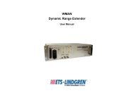
Frequency<br />
Response: 2 kHz - 3 dB<br />
400 kHz - 3 dB<br />
< 2 kHz 80 dB/decade rolloff<br />
> 400 kHz 40 dB/decade rolloff<br />
Figure 8n1<br />
HIn3637 Response Curve<br />
Detector Response: True RMS field indication for<br />
accurate measurement of<br />
non-sinusoidal waveforms.<br />
Dynamic Range: 100 dB
Page — 4 HIn3637 <strong>Manual</strong><br />
Ranges:<br />
Standard: 40 nT, 400 nT, 4 :T, 40 :T,<br />
400 :T full scale *<br />
Alternate Scale: 0.4 mG, 4 mG, 40 mG, 400<br />
mG, 4 G full scale *<br />
With A/m option: 30 mA/meter, 300<br />
mA/meter, 3 A/meter, 30<br />
A/meter, 300 A/meter full<br />
scale *<br />
* Multiply all values by 100 when using the optional X100<br />
probe<br />
Accuracy: ± 5% at calibration<br />
frequency<br />
Linearity: ± 2% Full Scale<br />
Recorder Out Level: 0 - 2.5 VDC, 25 :A<br />
maximum<br />
Recorder Out Jack: ¼ inch stereo phone jack<br />
Battery: 12 VDC, 1400 mA-h<br />
rechargeable Nickel-Cadmium<br />
(NiCd)<br />
Battery Life: Approximately 20 Hrs.<br />
continuous operation<br />
(full charge)<br />
Battery Charger: 110/220 VAC, 16 hour<br />
Environmental Operating<br />
Temperature: 0°C to 50°C (+32°F to<br />
+122°F)<br />
Humidity: 5% to 95% relative humidity,<br />
noncondensing
HIn3637 <strong>Manual</strong> Page — 5<br />
Instrument Package:<br />
Dimensions (Including<br />
connectors): 165 mm x 95 mm x 70 mm<br />
(6.5 in x 3.75 in x 2.75 in)<br />
Weight: 0.88 kg (31 oz)<br />
Standard Probe:<br />
Type: External, three-axis multi-turn loop<br />
I. D. (each loop): 110 mm (4.33 in)<br />
O. D. (each loop): 116 mm (4.57 in)<br />
Area (each loop): 0.010 m² (15.5 in²)<br />
Overall Diameter: 127 mm (5 in)<br />
Handle Length: 292 mm (11.5 in)<br />
Cable length: 1.5 meters (5 ft)<br />
Weight: 0.45 kg (16 oz)<br />
Optional X100 Probe:<br />
Type: External, three-axis single-turn loop<br />
Loop Dimension: 12.7 mm (.5 in) per side<br />
Area (each loop): 6.35 mm² (.25 in²) per side<br />
Overall Diameter: 34.3 mm (1.35 in)<br />
Overall Length: 292 mm (11.5 in)<br />
Cable length: 1.5 meters (5 ft)<br />
Weight: 0.31 kg (11 oz)
Page — 6 HIn3637 <strong>Manual</strong>
HIn3637 <strong>Manual</strong> Page — 7<br />
3.0 ACCEPTANCE AND CONTROLS<br />
Introduction<br />
This section contains information on: unpacking and<br />
acceptance of the HIn3637; the battery; the battery<br />
charger, and; all controls, indicators and connectors (refer<br />
to figure 3n2 for the location of these components).<br />
Unpacking and Acceptance<br />
Step 1. Upon delivery of your order, inspect the<br />
shipping container(s) for evidence of<br />
damage. Record any damage on the delivery<br />
receipt before signing. In case of concealed<br />
damage or loss, retain the packing materials<br />
for inspection by the carrier.<br />
Step 2. Remove the meter and probe from the<br />
shipping containers. Save the boxes and any<br />
protective packing materials for future use.<br />
Step 3. Check all materials against the packing list to<br />
verify that the equipment received matches<br />
that which was ordered. If you find any<br />
discrepancies, note them and call Holaday<br />
Customer Service for further instructions.<br />
Be sure that you are satisfied with the contents of your<br />
order and the condition of your equipment before using<br />
the meter.<br />
Battery<br />
The 12 VDC, 1400 mA-h NiCd battery provides up to 20<br />
hours of meter operation when fully charged.<br />
Battery Charger<br />
Refer to Figure 3n1 for the following step.<br />
Step 1. Check the viewing window on the power<br />
entry module to verify that the battery<br />
charger is set to the proper voltage for your<br />
AC power source. If not, change the setting<br />
via the following procedure: After ensuring<br />
that the charger is unplugged, use a small
Page — 8 HIn3637 <strong>Manual</strong><br />
screwdriver to pry loose the fuse assembly,<br />
which is located below the AC connector.<br />
Remove the assembly and locate the small<br />
PC Board on the back side. Slide the PC<br />
board from right to left to remove it from the<br />
fuse assembly: rotate this board so that the<br />
desired voltage indicator is right-side up,<br />
then reinsert it into the fuse assembly. The<br />
required voltage should now be visible in the<br />
viewing window. Firmly reseat the fuse<br />
assembly back into the power entry module.<br />
The charger is now ready to use. See section<br />
4 for the battery charging procedure.<br />
Figure 3n1<br />
End View of Charger<br />
NOTE:<br />
If the correct voltage is still not visible,<br />
contact Holaday Customer Service for
HIn3637 <strong>Manual</strong> Page — 9<br />
assistance.<br />
Controls, Indicators and Connectors<br />
The instrumentation is housed in a rugged aluminum<br />
chassis. The entire unit is shipped in a convenient<br />
carrying case. The protective foam liner inside the<br />
carrying case has cutouts which accommodate the meter,<br />
the detachable probe and the optional accessories offered<br />
for the meter.<br />
The probe consists of a sensing head containing three<br />
orthogonal coils oriented to pick up the X, Y, and Z<br />
components of the field. The detachable probe plugs into<br />
the multi-pin connector mounted on top of the chassis.<br />
The color coded label surrounding the probe connector<br />
will match the color of the band on the probe cover.<br />
The top of the chassis also contains a ¼ inch stereo<br />
phone jack. The jack is used to connect the battery<br />
charger and also provide access to the recorder output<br />
signal.<br />
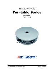
The rotary selector switch on the HIn3637 front panel<br />
controls power to the instrument and selects one of five<br />
measurement ranges. The scales are arranged so that<br />
when turned to the first position—400 :T/4 G (or 300<br />
Amps/meter if the optional kit is installed)—the meter is<br />
measuring on its least sensitive scale, i.e., highest range.<br />
As the switch is rotated clockwise, the sensitivity of the<br />
meter increases. As a general rule, readings will be most<br />
accurate when the meter movement shows maximum<br />
deflection without lighting the Over Range indicator.<br />
There are two indicators on the front panel. A "Low<br />
Battery" LED illuminates when the battery voltage is too<br />
low to provide accurate readings. At this point, testing<br />
should be discontinued and the battery recharged or<br />
replaced. The "Over Range" LED illuminates when the<br />
measured flux density exceeds full scale for the selected<br />
range.
Page — 10 HIn3637 <strong>Manual</strong><br />
Figure 3n2<br />
HIn3637 Front Panel<br />
Recorder Output<br />
The HIn3637 Magnetic Field Meter offers a recorder<br />
output. The recorder signal level is proportional to meter<br />
deflection, and varies between 0 and 2.5 VDC. This<br />
output signal can be used to drive a chart recorder,<br />
datalogger, or other device.<br />
The recorder output is accessed through the battery
HIn3637 <strong>Manual</strong> Page — 11<br />
charger connector (refer to Figure 3n3). This is a twoconductor<br />
jack that mates with a standard ¼ inch stereo<br />
phone plug. The ring of the phone plug is reserved for<br />
battery charger input and the tip is connected to the<br />
recorder output. The shaft of the plug is common<br />
ground. A diode in the charging circuit isolates the<br />
battery voltage from the recorder output when the plug<br />
is inserted into the jack.<br />
Figure 3n3<br />
¼ inch Stereo Phone Plug<br />
The same circuit drives both the meter movement and the<br />
recorder output. The maximum recorder output current<br />
is 25 microamperes, requiring a 100 KS minimum<br />
recorder output load; a lower impedance will affect the<br />
accuracy of both the meter reading and the recorder<br />
output voltage.<br />
Both the meter movement and recorder output are driven<br />
by a (PWM) pulse-width modulated signal from the<br />
microprocessor. This leads to a small amount of ripple.<br />
Low Battery Indication<br />
The HIn3637 Magnetic Field Meter includes a "Low<br />
Battery" indicator (LED) mounted on the front panel (refer<br />
to Figure 3n2). It is normal for this LED to flash briefly<br />
when switching ranges and when turning the instrument<br />
off.<br />
If the "Low Battery" indicator remains on during<br />
operation, the battery must be recharged. When the<br />
"Low Battery" LED lights, testing should be discontinued
Page — 12 HIn3637 <strong>Manual</strong><br />
and the battery recharged or replaced. This is due to the<br />
output characteristic of NiCd batteries: the voltage<br />
remains relatively constant until the battery is almost<br />
completely depleted, then drops very rapidly.
HIn3637 <strong>Manual</strong> Page — 13<br />
4.0 BATTERY CHARGING<br />
Introduction<br />
Each HIn3637 meter contains a rechargeable nickelcadmium<br />
(NiCd) battery. A fully-charged battery (nominal<br />
output voltage of 12 VDC) provides up to 20 hours of<br />
operation.<br />
NOTE:<br />
Holaday Industries, Inc., charges the internal<br />
NiCd battery of the HIn3637 at the factory in<br />
order to calibrate the instrument prior to<br />
shipment. While every effort is made to<br />
ensure that your meter arrives ready to use,<br />
we cannot guarantee that this will be the<br />
case. Always check the condition of the<br />
meter's battery prior to use.<br />
Battery Tips<br />
Nickel-Cadmium (NiCd) batteries have several<br />
characteristics that can affect both their performance and<br />
operating life. The following tips advise you how to take<br />
advantage of these characteristics to get the most out of<br />
your meter's battery.<br />
! Although NiCd batteries are rated for operation in<br />
temperatures from -20 °C to +65 °C (-4 °F to<br />
+140 °F), using the meter in extreme temperatures<br />
will reduce operating time significantly. The<br />
optimum operating temperature range for these<br />
batteries is +20 °C to +30 °C (+68 °F to +86<br />
°F).<br />
! The battery in the HIn3637 does not require<br />
periodic "deep discharges" to reverse the capacitydepleting<br />
"memory effect" caused by repeated<br />
shallow discharges; however, undercharging can<br />
reduce battery capacity.<br />
! If the battery appears unable to acquire or maintain<br />
an appreciable charge, individual cells in the battery<br />
may be shorted or damaged. If, for any reason, you<br />
need assistance replacing your battery contact<br />
Holaday Customer Service.
Page — 14 HIn3637 <strong>Manual</strong><br />
Charging Procedure<br />
Step 1. Verify that the battery charger is set<br />
correctly for the AC voltage in your area.<br />
Step 2. Plug the charger into a suitable AC source.<br />
Step 3. Set the meter switch to OFF. Insert the plug<br />
on the charger cable into the meter's ¼ inch<br />
stereo phone jack. The indicator on the<br />
charger lights up only when the<br />
instrumentation/readout package is<br />
connected.<br />
NOTE:<br />
The rotary selector switch must be in the OFF<br />
position for the battery to charge.<br />
Step 4. The battery is now charging. This may take<br />
up to 16 hours, depending on how deeply<br />
the battery is discharged.<br />
Charging Considerations<br />
Recharge the battery using either the standard trickle<br />
charger or the optional quick charger (See Table 5n2).<br />
Recharging a fully discharged battery will take up to 16<br />
hours with the trickle charger or one hour with the quick<br />
charger.<br />
Charge time can be reduced only by increasing the<br />
charging current. If this higher current level is not<br />
monitored carefully and charging stopped at the proper<br />
time, the battery may be permanently damaged. Holaday<br />
Industries offers an optional one-hour quick charger,<br />
developed in cooperation with a NiCd cell manufacturer.<br />
This charger is microcomputer controlled and can safely<br />
recharge the NiCd battery (at the maximum rate) in one<br />
hour. It uses an algorithm to determine full charge,<br />
allowing a battery in any state of discharge to be brought<br />
to full capacity without overcharging.<br />
There are a number of chargers available for this type of<br />
NiCd battery. Some do a very good job of charging the<br />
battery, others sacrifice battery life for decreased charge
HIn3637 <strong>Manual</strong> Page — 15<br />
time. The HIn3637 should be charged only with an<br />
approved battery charger.<br />
Battery Replacement<br />
A NiCd battery powers the HIn3637 Magnetic Field<br />
Meter (See Table 5n1). In the event of battery failure, a<br />
new battery can be obtained from Holaday Industries.<br />
NOTE:<br />
A #0 Phillips screwdriver works well for the<br />
following procedure.<br />
To replace the battery, remove the eight screws located<br />
around the lip of the meter's front panel, pull the panel<br />
away from the chassis and unplug the battery connector.<br />
Remove the battery retainer and the old battery. Install<br />
the new battery and reverse the above steps to<br />
reassemble the meter.<br />
CAUTION<br />
Never short the terminals of a NiCd battery (even a<br />
discharged battery). The resulting current may be excessive<br />
and cause the lead wires to become extremely hot, which<br />
can result in severe burns and/or fire.
Page — 16 HIn3637 <strong>Manual</strong>
HIn3637 <strong>Manual</strong> Page — 17<br />
5.0 MAINTENANCE<br />
Introduction<br />
This section explains which maintenance tasks can be<br />
performed by the user. It also provides information<br />
regarding replacement and optional parts. If you have<br />
any questions concerning probe maintenance, consult<br />
Holaday Customer Service.<br />
Maintenance Recommendations<br />
Maintenance of the HIn3637 is limited to external<br />
components such as cables or connectors.<br />
Any calibration or maintenance task which requires<br />
disassembly should be performed at the factory. Check<br />
with Holaday Customer Service (952-934-4920) before<br />
opening the unit as this may affect your warranty.<br />
Return Procedures<br />
To return an instrument to Holaday, use the following<br />
procedures:<br />
Step 1. Briefly describe the problem in writing. Give<br />
details regarding the observed symptom(s),<br />
and whether the problem is constant or<br />
intermittent in nature. If you have talked<br />
previously to Holaday Customer Service<br />
about the problem, provide the date(s), the<br />
name of the service representative you spoke<br />
with, and the nature of the conversation.<br />
Include the serial number of the item being<br />
returned.<br />
Step 2. Package the instrument carefully. Use the<br />
original carrying case, if possible. If not, use<br />
the Parts List in Table 5n1 to order a new<br />
case and foam packing from Holaday<br />
Industries, Inc.<br />
NOTE:<br />
If your meter is calibrated in accordance with<br />
MIL-Std-45662A, it is greatly to your benefit<br />
to retain the original shipping box and packing
Page — 18 HIn3637 <strong>Manual</strong><br />
materials. One of the criteria for certifying a<br />
calibration to MIL standards requires Holaday<br />
Industries to always ship equipment in the<br />
specified packaging. When a MIL Standard<br />
instrument is sent to Holaday in other<br />
packaging, we must replace it with the<br />
specified packaging materials for return<br />
shipment. YOU WILL BE BILLED FOR THE<br />
NEW PACKAGING.<br />
If the instrument is under warranty, refer to the Limited<br />
Warranty at the front of this manual for additional<br />
information about your return.<br />
Periodic/Preventive Maintenance<br />
The HIn3637 requires an annual calibration check to<br />
verify that it is performing within specifications. This<br />
calibration check may be performed by Holaday Service<br />
Personnel at the factory. Return your meter(s), using the<br />
original packing materials (if possible), to:<br />
Holaday Industries Inc.<br />
Attn. Service Department<br />
14825 Martin Drive<br />
Eden Prairie, MN USA 55344
HIn3637 <strong>Manual</strong> Page — 19<br />
Parts Information<br />
Use the tables below for ordering replacement (Table<br />
5n1) or optional (Table 5n2) parts for the HIn3637.<br />
Table 5n1. Replacement Parts List<br />
Part Description (Replacement Parts) Part Number<br />
Battery, 12 VDC, Rechargeable 491069<br />
Universal 12V Trickle Charger<br />
(110/220 Volt)<br />
491063-05<br />
Carrying Case 491085<br />
HIn3637 User's <strong>Manual</strong> 600055<br />
Table 5n2. Optional Parts List<br />
Part Description (Optional Parts) Part Number<br />
X100 VLF Probe Assembly 491076<br />
Amps/meter Kit 651006<br />
Probe Mount 491050
Page — 20 HIn3637 <strong>Manual</strong>
HIn3637 <strong>Manual</strong> Page — 21<br />
6.0 MAKING MEASUREMENTS<br />
Quick Start<br />
For experienced users, or for those who particularly<br />
dislike reading operating descriptions, the following is a<br />
quick start procedure to get you up and running as soon<br />
as possible:<br />
NOTE:<br />
This meter uses the same probe connector as<br />
Holaday's HIn3627 ELF Magnetic Field Meter.<br />
Consequently, if you use both meters, it is<br />
possible to connect the probe from one meter<br />
to the instrumentation/readout package of the<br />
other meter, resulting in erroneous readings.<br />
To prevent this, color bands are placed on<br />
both the probe and the readout: on the probe,<br />
the color band surrounds the center of the<br />
spherical probe housing; on the readout, the<br />
color band surrounds the multi-pin connector<br />
at the top of the chassis. The colors used are<br />
orange (HIn3627) and yellow (HIn3637).<br />
When performing Step 1, below, be sure the<br />
color band on the probe matches the color<br />
band on the instrumentation/readout package.<br />
Step 1. Plug the probe into the multi-pin connector<br />
at top of the meter.<br />
Step 2. Turn the meter on by rotating the range<br />
selector switch one position clockwise.<br />
NOTE:<br />
The Battery Low LED will flash momentarily<br />
when the meter is turned on.<br />
Step 3. Verify that neither the Over Range nor<br />
Battery LEDs are illuminated.<br />
Step 4. Make measurements with the range selector<br />
switch set for the maximum reading without<br />
an over range indication.
Page — 22 HIn3637 <strong>Manual</strong><br />
NOTE:<br />
The meter will not operate when the battery<br />
charger is connected to the charger jack.<br />
Description<br />
To begin making field measurements, connect the probe<br />
to the meter. Turn the range switch clockwise,<br />
increasing the instrument's sensitivity until an up-scale<br />
meter reading is obtained. Readings will be most<br />
accurate when the selected range yields maximum needle<br />
deflection without lighting the Over Range LED. When an<br />
over range indication occurs, select the next larger range.<br />
Since the meter movement is protected against deflection<br />
past the top of the meter scale, the "Over Range" LED<br />
must be used to determine an over range condition.<br />
The probe utilizes three mutually-perpendicular concentric<br />
coils it is not necessary to rotate the sensor to obtain a<br />
maximum indication on the meter.
HIn3637 <strong>Manual</strong> Page — 23<br />
7.0 THEORY OF OPERATION<br />
Introduction<br />
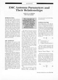
The circuitry of the HIn3637 can be divided into seven<br />
sections: probe, range select, pre-filter, integrator, postfilter,<br />
RMS calculation and the power supply. Each of<br />
these is discussed in the follow sections (see Figure<br />
7n1).<br />
Probe<br />
The probe consists of three orthogonal concentric<br />
shielded coils aligned such that their axes are mutually<br />
perpendicular. Each coil's electrostatic shield is isolated<br />
from that of the others: the shields are connected at a<br />
single point at the base of the sphere defined by the<br />
coils. The signal from each coil is routed to the meter<br />
through a shielded twisted-pair cable: this cable's shield<br />
is also connected to the common point of the coil<br />
electrostatic shields.<br />
Range Select<br />
The output voltage of a coil varies with the frequency of<br />
the applied magnetic field. In order to accommodate the<br />
magnetic field amplitudes and frequencies that the<br />
HIn3637 is designed to measure, a set of selectable<br />
attenuators is used to ensure that the input voltage to the<br />
remaining circuitry is at the proper level for the selected<br />
range.<br />
Pre-filter Section<br />
Each channel is filtered separately. A fourth-order highpass<br />
Butterworth filter is used to insure that only signals<br />
with a frequency of 2000 Hz or greater reach the<br />
integrator. The Butterworth filter attenuates the signal by<br />
3 dB at the cutoff frequency, has maximum attenuation<br />
in the stop band, and has no ripple in the passband.
Page — 24 HIn3637 <strong>Manual</strong><br />
Figure 7n1<br />
Block Diagram
HIn3637 <strong>Manual</strong> Page — 25<br />
Integrator Section<br />
The output voltage of the probe sensor coils increases<br />
directly with the frequency of the applied magnetic field.<br />
The integrator provides a flat frequency response.<br />
Post-filter Section<br />
A second-order Butterworth low-pass filter ensures that<br />
only signals below 400 kHz are fed to the RMS<br />
calculation section.<br />
RMS Calculation<br />
The signal from each channel is applied to a separate true<br />
RMS converter and combined through vector addition to<br />
obtain the field magnitude. This value is computed by<br />
the processor and A/D converter. The meter is driven by<br />
outputs configured as a PWM (Pulse-Width Modulator).<br />
The processor performs an A/D conversion on each axis<br />
signal by programming the analog multiplexer, which<br />
feeds the A/D converter. The digital values are squared<br />
and summed; then the square root of the sum is<br />
calculated. This result determines the duty cycle of the<br />
PWM output, which drives the meter movement. The<br />
PWM output frequency is 30 Hz; this is too high to be<br />
visible on the analog meter, but it can be detected on the<br />
recorder output as approximately 50 mV of ripple.<br />
Power supply<br />
A ten-cell NiCd battery powers the HIn3637. The<br />
current consumption of the instrument is relatively low,<br />
yielding a continuous operating time of 20 hours. In<br />
typical daily operation (intermittent use), the operating<br />
time between charges will be much greater. The voltages<br />
required by the analog circuitry are derived directly from<br />
the battery voltage. The digital voltage is supplied via a<br />
series pass regulator.
Page — 26 HIn3637 <strong>Manual</strong>
HIn3637 <strong>Manual</strong> Page — 27<br />
8.0 CALIBRATION<br />
The HIn3637 is calibrated using a Helmholtz coil<br />
(consisting of two close-coupled windings) one meter in<br />
diameter to establish an accurate, known magnetic field<br />
flux density. A precisely controlled and measured<br />
sinusoidal current is driven through the coils and, based<br />
on the dimensions of the coils, the magnetic field flux<br />
density between the coils is calculated.<br />
Each axis is individually calibrated. Calibration is<br />
performed at a frequency of 20 kHz, and verified at 232<br />
kHz, at a flux density level of 10 mG. The out of band<br />
response is checked at 60 Hz and 700 kHz. All calibration<br />
is traceable to NIST.<br />
The HIn3637 indicates magnetic flux density (B) in units<br />
of Tesla/Gauss. The flux density in microteslas or the<br />
magnetic field strength (H) in milliamperes per meter are<br />
related as follows:<br />
1 mG = 0.1 microtesla (:T)<br />
1 mG = 80 milliamperes per meter (mA/m)<br />
The recommended calibration interval is one year.<br />
Holaday Industries offers complete calibration services<br />
which comply with MILnSTD 45662A.
Page — 28 HIn3637 <strong>Manual</strong>
HIn3637 <strong>Manual</strong> Page — 29<br />
9.0 REFERENCES<br />
(1) IEEE Standard Procedures for Measurement of Power<br />
Frequency Electric and Magnetic Fields from AC Power<br />
Lines. ANSI/IEEE standard 644n1987. Published by The<br />
Institute of Electrical and Electronics Engineers, Inc., 345<br />
East 47th Street, New York, NY 10017. Approved<br />
November 17, 1986.<br />
(2) Swedish National Board for Measurement and Testing,<br />
Test Methods for Visual Display Units—Visual<br />
Ergonomics and Emission Characteristics. MPR 1990:8,<br />
1990n12-01, National Board for Measurement and<br />
Testing, Box 878, S-501 15 Bors, Sweden.<br />
(3) Electric and Magnetic Field Measurements and Possible<br />
Effects on Human Health from Appliances, Power Lines,<br />
and Other Common Sources. Special Epidemiological<br />
Studies Program, California Department of Health<br />
Services, 2151 Berkeley Way, Room 704, Berkeley, Ca.<br />
94704 (415) 540-2669
Page — 30 HIn3637 <strong>Manual</strong>
HIn3637 <strong>Manual</strong> Page — 31<br />
APPENDIX A<br />
VIDEO DISPLAY TERMINALS (VDTs)<br />
VDT CHARACTERISTICS<br />
General Description<br />
Video display terminals (VDT's) and television receivers<br />
are quite similar in certain respects. Both are used to<br />
display information; the VDT displaying information<br />
received from a computer system, word processing<br />
system, or other digital information system and the<br />
television receiver displaying video information<br />
transmitted from television broadcast stations. In<br />
conjunction with a keyboard, the VDT serves as the main<br />
interface between the operator and a word processor,<br />
computer, etc. Television receivers are sometimes used<br />
in lieu of VDT's with home computer systems.<br />
Principles of Operation<br />
VDT's and television receivers use the same basic<br />
principles of operation. Both contain a large evacuated<br />
glass tube called a cathode-ray tube (CRT), or picture<br />
tube in the case of television receivers. The CRT<br />
contains a source of electrons (the cathode) at one end<br />
and a fluorescent coating on the inside of the viewing<br />
screen. Electrons released from the cathode are<br />
accelerated by a high voltage (typically in the range of 10<br />
to 25 kilovolts) and are projected onto the fluorescent<br />
material of the screen which then emits visible light when<br />
it is struck by the fast-moving electrons. The CRT also<br />
includes various electrodes for focusing the electron<br />
beam and for scanning the beam across the fluorescent<br />
screen. Electronic circuitry in the VDT modulates the<br />
electron beam to produce the intended images on the<br />
screen. This circuitry leads to the production of<br />
electromagnetic fields (emissions). There are four basic<br />
aspects to the electrical environment of VDT emissions:<br />
(1) 60/50 Hz modulated DC fields; (2) 60/50 Hz fields;<br />
(3) RF fields associated with the horizontal and vertical<br />
deflection systems; (4) broadband RF fields caused by the<br />
digital electronic circuits which are associated with<br />
character generation (Roy, et al, 1983).
Page — 32 HIn3637 <strong>Manual</strong><br />
Modulated DC Fields<br />
To accelerate the electron beam toward the screen, a<br />
high DC voltage is used. The high voltage is produced by<br />
pulsing a transformer which has a high turns ratio and is<br />
often derived from the deflection circuitry, though in<br />
some cases it may have a higher frequency depending on<br />
the character display system. The drive pulse is a square<br />
wave which produces a high voltage secondary pulse that<br />
is rich in harmonic content. The AC components of this<br />
DC current pulse flow to ground via the capacitance<br />
formed by the CRT screen and the resistive coating on<br />
the outside of the CRT. This small capacitance provides<br />
the filtering necessary for a smooth high voltage<br />
accelerating potential. Roy, et al, (1983) have reported<br />
that one method of reducing the AC component of the<br />
DC field is to place an RC filter network between the high<br />
voltage transformer output and the CRT. They found<br />
that such a filter could, in some VDT's, reduce the AC<br />
component of the DC field by as much as 50 dB (a factor<br />
of over 300 times).<br />
The modulated DC field is produced by the charge on the<br />
face of the CRT and is largely confined to the front of the<br />
unit. This field is highly variable, being affected by<br />
humidity, capacitance between the CRT and external<br />
objects and touching the CRT (Harvey, 1984a). Several<br />
investigators have measured the strength of this DC field<br />
and found values ranging from a few hundred volts per<br />
meter to as high as 45 kV/m at the surface of the body<br />
of an operator, and depending on the proximity of the<br />
operator to the VDT, closer distances resulting in higher<br />
measured incident DC fields (Olsen, 1981; Harvey,<br />
1984b; Nylen, et al, 1984; Bracken, et al, 1985).
HIn3637 <strong>Manual</strong> Page — 33<br />
60/50 Hz Fields<br />
These fields are caused primarily by the current flowing<br />
in the vertical deflection coil and are nearly symmetrical<br />
around the coil. It is produced by the same mechanism<br />
that produces the DC field; the charge on the VDT screen<br />
which produces the DC field is actually not constant but<br />
builds up and decays by a small amount each time the<br />
display is scanned by the electron beam. This occurs at<br />
a nominal 60 Hz rate although harmonics may exist up to<br />
several kHz (Harvey, 1983a). Measurements of the 60 Hz<br />
emissions and harmonics by Stuchly, et al, (1983) found<br />
magnetic field strengths of 100 to 200 mA/m at a<br />
position 30 cm in front of the VDT. Harvey (1984b)<br />
reported measured 60 Hz AC electric field strengths of<br />
between 5 and 60 V/m in an investigation of five VDTs.<br />
These relatively low values are in the range of other<br />
commonly encountered 60 Hz appliances found in the<br />
home and office environment.<br />
Deflection System Fields<br />
The principal RF component of VDT emissions is caused<br />
by the so-called flyback transformer circuitry which is<br />
responsible for a rapidly changing current which flows in<br />
the horizontal deflection coils of the VDT and causes the<br />
electron beam to be rapidly swept to the left side of the<br />
screen, ready for another trace across the screen. The<br />
rate at which the electron beam is scanned is dependent<br />
on the particular design of the VDT but typically falls in<br />
the range of 17 to 30 kHz. For television receivers, the<br />
flyback frequency is approximately 15.75 kHz.<br />
The flyback circuit is rich in harmonic production and any<br />
instrument intended for accurate assessment of RF<br />
exposure fields produced by VDT's must be capable of<br />
true RMS measurement. The strong harmonic content of<br />
the flyback signal means that it has a non-sinusoidal<br />
waveform; the HIn3637 incorporates a true RMS<br />
detector circuit which can accurately respond to the<br />
complex waveforms observed near VDT's.<br />
Approximately 95 percent of the total energy of the<br />
flyback circuit emissions is contained within the first five<br />
or six harmonics. Consequently, the bandpass of the HI-<br />
3637 has been tailored to the necessary frequency range
Page — 34 HIn3637 <strong>Manual</strong><br />
to capture all the important harmonics.<br />
In addition to the horizontal sweep-frequency circuit,<br />
there is a vertical deflection circuit which is used to<br />
deflect the electron beam down the CRT screen and in so<br />
doing produce characters. The vertical sweep frequency<br />
is approximately 60 Hz.<br />
The horizontal deflection circuit operates on the principle<br />
that the force exerted on a moving electron is at right<br />
angles to both the direction of the electron's motion and<br />
the applied magnetic field. To induce a horizontal<br />
component to the electron's original direction, the<br />
magnetic field must possess a vertical polarization. Thus,<br />
the horizontal deflection coils in VDT's and television<br />
receivers tend to generate magnetic fields which are<br />
strongly vertically polarized near the front of the screen.<br />
RF fields caused by the deflection circuitry can produce<br />
electric fields at normal operator positions of typically a<br />
few V/m up to some tens of V/m and magnetic fields in<br />
the range of a few mA/m up to several hundred mA/m<br />
(Harvey, 1983b; Guy, 1987; Boivin, 1986; Joyner, et al,<br />
1984; Marha and Charron, 1983). The HI-3637 is<br />
designed specifically for measurement of the RF fields<br />
associated with the beam deflection systems in VDT's<br />
and television receivers.<br />
Broadband RF Fields<br />
An electronic clock within the VDT which typically<br />
operates in the frequency range of 1 to 20 MHz is the<br />
source of most of the radiated RF signals from the digital<br />
electronics sub-section (Roy, et al, 1983). Conventional<br />
shielding techniques are the usual method for eliminating<br />
or reducing such emissions. Petersen, et al, (1980) and<br />
Weiss and Petersen (1979) evaluated RF emissions from<br />
a number of VDT's and found that RF electric field<br />
strengths, measured at a distance of 1.5 meters from the<br />
front of the VDT, for those emissions not associated with<br />
the flyback circuit were well below 1 V/m RMS, typically<br />
less than 0.01 V/m.
HIn3637 <strong>Manual</strong> Page — 35<br />
CHARACTERIZING VDT EMISSIONS AND OPERATOR<br />
EXPOSURE<br />
Introduction<br />
Because of the perturbing influence of the measured<br />
electric field strength values near VDT's, it is important<br />
to distinguish between assessments of operator exposure<br />
and basic emission characteristics of VDT's. Relative to<br />
electric fields, these two properties are not the same.<br />
Characterizing VDT Emissions<br />
On occasion it is desirable to characterize the<br />
electromagnetic emissions of a number of VDT's, such as<br />
in a large office situation, to establish the general<br />
emission levels of these VDT's for comparison with other<br />
VDT emission data. Such measurements can be used to<br />
determine unusual operating characteristics of particular<br />
VDT's within a group. To collect this type of data, it is<br />
helpful to minimize unnecessary, extraneous<br />
environmental factors.<br />
Emission characterizations should therefore be performed<br />
without the operator present. Although the literature<br />
contains numerous methods by which emission data have<br />
been obtained, the principal difference lies in the<br />
locations about the VDT at which measurements are<br />
performed. An exploration of the surfaces of a typical<br />
VDT will reveal areas of particularly intense fields, but<br />
these areas are usually on the sides or top of the VDT<br />
and are not directly applicable to frontal area exposure<br />
where the operator would be positioned. Because of this,<br />
a nearly universal measurement location—positioned at a<br />
point 30 cm directly in front of the VDT screen—has<br />
been commonly used and recommended in emission<br />
characterizations (FDA, 1984).<br />
Measurement distances of 50 cm and 1 m have also been<br />
used. The value of 30 cm actually represents a quite<br />
close distance when compared to the viewing distance<br />
used by many VDT operators. In fact, a minimum<br />
viewing distance closer to 36 cm has been recommended<br />
(Diffrient, et al, 1981). Nevertheless, because the value<br />
of 30 cm has been so often reported in the literature,
Page — 36 HIn3637 <strong>Manual</strong><br />
measurements should at least include this distance<br />
among possible others.<br />
VDT emission data reported in the literature show that in<br />
most instances a fixed screen condition has been used to<br />
promote more repeatable measurements. For example, a<br />
commonly reported method involves filling the screen<br />
with a single character such as an E or M and adjusting<br />
the brightness and contrast controls to their maximum<br />
position. In contrast to these precautions, it has also<br />
been reported that these measures often seem to have<br />
very little, if any, impact on the resulting measured values<br />
of electric and magnetic field strength (Roy, et al, 1983).<br />
Nevertheless, because of peculiarities of some VDTs, a<br />
check of the effect of varying the brightness and contrast<br />
controls should be made. Roy, et al (1983), suggest that<br />
CRT performance, which decreases with age, and the<br />
type of video generating system used are two possible<br />
factors responsible for this phenomenon.<br />
Measurements of the magnetic field strength are<br />
considerably less difficult since the presence of the<br />
human body does not perturb the magnetic field.<br />
Distances are measured between the screen surface and<br />
the center of the probe for magnetic field values. As the<br />
distance between the probe and the screen is decreased,<br />
greater error will exist in the indicated value of magnetic<br />
field strength. This spatial averaging error diminishes<br />
rapidly with distance from the VDT since the field rapidly<br />
becomes more uniform.<br />
Because the magnetic field gradients are so great near the<br />
VDT, significant error may occur if extra care is not<br />
exercised when attempting repeated measurements at a<br />
specific location. This is apparent when holding the<br />
instrument without a tripod very near the screen and<br />
attempting to obtain a constant reading of field strength.
HIn3637 <strong>Manual</strong> Page — 37<br />
GUIDELINES FOR RF EXPOSURE<br />
To provide a means for judging the significance of<br />
measured magnetic field emissions found near VDT's, the<br />
scientific literature can be examined for information on<br />
suggested exposure or emission limits. The exposure<br />
standards reviewed at the time of this manual's<br />
preparation apply to humans for the purpose of<br />
establishing safe working or living environments where<br />
magnetic fields exist. The exposure limits compiled in<br />
this manual are those found that correspond most closely<br />
to the predominant frequency range of VDT's. In some<br />
cases, the standards apply to occupational exposure<br />
environments and in other cases, to the general living<br />
environment; often standards for this latter case are<br />
referred to as general population or public exposure limits.<br />
Traditional approaches to radiation protection, principally<br />
derived from ionizing radiation protection practices,<br />
usually differentiate between occupational and public<br />
exposure. Generally, occupational exposure limits are<br />
higher, i.e., more permissive, than public limits. This is<br />
because of the greater uncertainties associated with the<br />
general public; in the work place, employees are generally<br />
healthier, and possible exposure to potentially hazardous<br />
physical agents is usually under much better control. For<br />
example, employers can inform workers of situations<br />
which should be avoided; this is not the case for the<br />
general population. Regardless of these considerations,<br />
it is informative to examine some of the recommended<br />
exposure guides that apply to different organizations<br />
and/or countries.<br />
Table 1 summarizes the electromagnetic field exposure<br />
standards found in the literature that either directly apply<br />
to the frequency range appropriate to VDT emissions or<br />
pertain to a frequency range close to that of interest. As<br />
can be seen, the primary difficulty in applying many RF<br />
exposure standards to VDT emission levels is that the<br />
applicable frequency range of the standards does not<br />
extend low enough. From the literature searched, only<br />
one reference was found that offered a quantitative<br />
emission limit as a guideline specific to VDT's (Telecom,
Page — 38 HIn3637 <strong>Manual</strong><br />
1984). This Occupational Health Policy Guideline for<br />
VDT screen-based equipment was developed by Telecom<br />
Australia for internal use until such time as there is a<br />
national standard for VDTs in Australia. The guide<br />
specifies that the levels of radiation emitted from<br />
cathode-ray VDT's in the frequency range of 50 Hz to<br />
0.3 MHz shall be as low as possible, and should not, at<br />
any time, exceed an electric field strength of 50 V/m,<br />
measured 30 cm from the terminal.<br />
The reader of this manual is cautioned that a number of<br />
RF exposure standards are presently under development<br />
or revision and that Table 1 should be used more as an<br />
orientation to existing standards.
HIn3637 <strong>Manual</strong> Page — 39<br />
Table 1.<br />
Radio Frequency Exposure/Emission Standards Pertinent to<br />
the VDT Frequency Range.<br />
Standard/Reference Frequency (kHz) E (V/m) RMS H (gauss) RMS<br />
ACGIH 0 ) 0.1 25000 ---<br />
0.1 ) 4 2500/f (1) 0.6/f (1)<br />
4 ) 30 625 ---<br />
IEEE C95.1 3 ) 100 614 2.05<br />
IRPA 50/60 (Hz) 5000 1.0<br />
(gen. pop. 24 hr.)<br />
Swedish .005 ) 2 25 .0025<br />
Guidelines (2) 2 ) 400 2.5 .00025<br />
UK(1986)(occ) 750 Hz - 50 kHz 2,000 1.25<br />
UK(1986)(public) 750 Hz - 50 kHz 800 .05<br />
USSR(public) 0.03 - 0.3 25 ---<br />
(Slesin, 1985)<br />
(1) Frequency in KHz<br />
(2) These guidelines are not based on biological effects.<br />
They are based on what was technically possible.
Page — 40 HIn3637 <strong>Manual</strong><br />
-- NOTES --