Gate Controller ATC 100 Installation and Operating ... - ASO Safety
Gate Controller ATC 100 Installation and Operating ... - ASO Safety
Gate Controller ATC 100 Installation and Operating ... - ASO Safety

You also want an ePaper? Increase the reach of your titles
YUMPU automatically turns print PDFs into web optimized ePapers that Google loves.
<strong>Gate</strong> <strong>Controller</strong> <strong>ATC</strong> <strong>100</strong><br />
<strong>Installation</strong> <strong>and</strong><br />
<strong>Operating</strong> Manual<br />
Antriebs- und Steuerungstechnik<br />
Am Grarock 8 • D-33154 Salzkotten<br />
Tel.: 0 52 58/93 27-0 • Fax: 0 52 58/34 48<br />
www.asogmbh.de • e-mail: info@asogmbh.de
2<br />
<strong>Gate</strong> <strong>Controller</strong> <strong>ATC</strong> <strong>100</strong><br />
1. Important safety warnings<br />
2. General .................................................................................................................................. 4<br />
2.1 Highest safety for humans <strong>and</strong> objects ............................................................................................................. 4<br />
2.1 The advantages of the <strong>ATC</strong> <strong>100</strong> ............................................................................................................................. 4<br />
3. System components ............................................................................................................... 5<br />
3.1 LED - indicators ....................................................................................................................................................... 6<br />
4. Electrical connection ............................................................................................................. 7<br />
4.1 Mains voltage ............................................................................................................................................................ 8<br />
4.1.1 Connection three-phase motor ................................................................................................................................. 8<br />
4.1.2 Connection single-phase motor ............................................................................................................................... 9<br />
4.2 Relay outputs (potential free) ............................................................................................................................. 10<br />
4.3 STOP inputs ........................................................................................................................................................... 11<br />
4.4 Inputs for control switches ................................................................................................................................... 11<br />
4.5 Light-barrier inputs ................................................................................................................................................ 11<br />
4.6 <strong>Safety</strong>-contact-edge connection ......................................................................................................................... 12<br />
4.7 Limit switches inputs ............................................................................................................................................ 12<br />
4.8 Power supply 24V .................................................................................................................................................. 12<br />
5. Plug-on modules .................................................................................................................. 13<br />
5.1 Control modules ....................................................................................................................................................... 13<br />
5.2 Auxiliary modules ..................................................................................................................................................... 13<br />
5.2.1 Inductive safety controller ISK 70-75 ...................................................................................................................... 13<br />
5.2.2 Time switch ZU3 .....................................................................................................................................................13<br />
5.2.3 Radio controller ..................................................................................................................................................... 13<br />
6. Program settings .................................................................................................................. 14<br />
6.1 Automatic ................................................................................................................................................................. 14<br />
6.2 Manual mode ......................................................................................................................................................... 14<br />
6.3 Input ...................................................................................................................................................................... 14<br />
6.4 Diagnosis .............................................................................................................................................................. 16<br />
7. Jumper settings<br />
8. Article numbers<br />
9. Enclosure .............................................................................................................................17<br />
9.1 Mounting of the enclosure .................................................................................................................................... 17<br />
9.2 Enclosure dimensions ........................................................................................................................................ 17<br />
10.Technical data<br />
Contents<br />
..................................................................................................... 3<br />
.................................................................................................................... 17<br />
.................................................................................................................... 17<br />
..................................................................................................................... 18
1. Important safety notes<br />
• This manual must be available at the installation place of the gate controller at all time.<br />
Any person assigned with the installation, operation <strong>and</strong> maintenance of the gate controller must read <strong>and</strong> follow this manual.<br />
• Basic condition for safety-related h<strong>and</strong>ling <strong>and</strong> the failure-free operation of the gate controller is the knowledge of the fundamental<br />
safety guidelines <strong>and</strong> the safety regulations of the European st<strong>and</strong>ards <strong>and</strong> the professional associations.<br />
• This manual, in particular the safety guidelines, are to be considered from all persons who works on the gate controller<br />
• For safety reasons the electrical installation is only to accomplished from a qualified electrical personnel according to the locally<br />
valid regulations for the prevention of accidents.<br />
• The opening of the gate-controller is only permitted with switched off power supply. For the disconnection of the power supply a<br />
main power switch or the use of a CEE plug is to be planned. The main power switch or the power supply plug must be easily<br />
accessible.<br />
• Before performing any work on the gate controller, the voltage must be disconnected <strong>and</strong> verified that there is no live voltage.<br />
• If the potential free contacts of the relay outputs are connected to a dangerous voltage, it is also necessary to switch off these voltages<br />
before working on the gate controller.<br />
• The operation of the control with an opened enclosure is not permitted.<br />
• Switching on <strong>and</strong>/or operation of a dewed gate controller is not permitted <strong>and</strong> can destroy the controller.<br />
• The used stage nipple cable insertion may only cut to the stage, so that the insertion of the cable corresponds to the IP 54<br />
protection against water <strong>and</strong> foreign objects.<br />
Damaged stage nipples must be exchanged immediately against intact.<br />
• The intended use of the safety controller is the use at gates <strong>and</strong> doors. A different, or beyond this, use is not intended. The<br />
manufacturers do not assume liability for damages <strong>and</strong> malfunctions caused by not intended use.<br />
The manufacturer must permit the use in special applications.<br />
• Faults, which can affects the safety, must be eliminated immediately.<br />
• With the use of the gate in the manual mode operation it is to be guaranteed that the gate range can be seen by the operator.<br />
• At the start-up operation <strong>and</strong> at the annually prescribed maintenance the parameter settings <strong>and</strong> the correct function of the safety<br />
device must be examined.<br />
The settings of the parameters <strong>and</strong> the maintenance of the gate situation may only checked by a qualified personnel. The results must<br />
be documented in such a way that it can be viewed <strong>and</strong> understood at any time.<br />
• Never allow that children operate the gate controller. Take care that children don't play in the near or with the gate. Keep radio remote<br />
controllers in a place which is inaccessible to children.<br />
• The manufacturer <strong>and</strong> the user of the gate, at which the controller is used, are responsible for the compliance with all valid safety<br />
regulations.<br />
• The gate controller guarantees for itself a functional safety, however not the complete safety of the gate. Therefore, a safety<br />
consideration for the complete gate, according to the machinery directive 98/37 EC or to the appropriate product st<strong>and</strong>ard, is necessary<br />
before using this gate controller.<br />
• The gate controller contains no user-serviceable parts. Any unauthorised modifications <strong>and</strong>/or repairs of the gate controller will<br />
terminate any guarantee <strong>and</strong> claim against the manufacturer.<br />
The <strong>ATC</strong> <strong>100</strong> gate controller must be regarded as a component.<br />
It lies in the responsibility of the gate manufacturer <strong>and</strong>/or gate operator to ensure that its gate<br />
meets all relevant regulations <strong>and</strong> st<strong>and</strong>ards (machinery directive, EMC guideline etc.).<br />
Technical <strong>and</strong> operating relevant changes to the products <strong>and</strong> devices specified in this documentation<br />
are reserved at any time also without advance notice.<br />
3
4<br />
<strong>Gate</strong> <strong>Controller</strong> <strong>ATC</strong> <strong>100</strong><br />
2. General<br />
The free parametrizable gate controller <strong>ATC</strong> <strong>100</strong> is developed for controlling 400V three-phase current <strong>and</strong> 230V onephase<br />
current motors on sliding gates, roller doors, roller grills, <strong>and</strong> sectional doors in industrial, commercial <strong>and</strong><br />
private use. As a result of the large flexibility, the variety of connection possibilities <strong>and</strong> the combination with further<br />
optional plug-on modules the gate controller <strong>ATC</strong> <strong>100</strong> can be used in many areas.<br />
By the menu-driven programming of the <strong>ATC</strong> <strong>100</strong> it is succeeded to simply arrange a complex control that fulfils<br />
many requirements <strong>and</strong> functions.<br />
2.1 Highest safety for humans <strong>and</strong> object<br />
• Complete testing of all safety-related parts before each gate movement<br />
• Testing the contactor contacts on correct function before each movement<br />
• In case of an error a second shut-down circuit for the motor current is available by the additional release contactor.<br />
As a compact unit the <strong>ATC</strong> <strong>100</strong> fulfils the requirements of the latest gate st<strong>and</strong>ards.<br />
2.2 The advantages of the <strong>ATC</strong> <strong>100</strong><br />
• compact enclosure<br />
• connecting possibility for three-phase <strong>and</strong> one-phase motors<br />
through the integrated reversing contactors<br />
• simple, menu-driven programming of the controller by four<br />
buttons<br />
• if necessary the pluggable control module offers protection<br />
against unauthorized access of the adjusted parameters<br />
• malfunction <strong>and</strong> operating conditions are indicated by the<br />
two-line LCD display <strong>and</strong> by Led's<br />
• integrated two-channal evaluation for stationary safety<br />
contact edges<br />
• socket for inductive safety system ISK to monitoring the<br />
travelling safety contact edges at the gate wing<br />
• socket for timer<br />
• socket for radio controller<br />
• alternatively complete or partial automatic revision after<br />
operating the safety contact edges<br />
• pluggable connecting terminals for simpler assembly<br />
• ALL-IN-ONE solution for the gate-automation
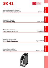
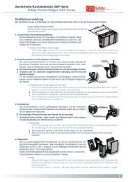
3. System components<br />
1<br />
2<br />
3<br />
4<br />
5<br />
6<br />
7<br />
8<br />
9<br />
10<br />
11<br />
12<br />
13<br />
23<br />
20<br />
7<br />
12<br />
Terminal clamps supply voltage, motor<br />
Terminal clamps light <strong>and</strong> brake<br />
Terminal clamps inputs<br />
Fuse 2AT/250V<br />
Reversing contactor<br />
Release contactor<br />
Control module<br />
Menu selection button<br />
Function button<br />
Close (-) button<br />
Open (+) button<br />
Jumper J1<br />
Jumper J2<br />
22<br />
MENU OK<br />
+<br />
4<br />
1<br />
2<br />
18<br />
19<br />
Supply Voltage<br />
3 x 400 V 50 Hz<br />
M<br />
Light<br />
Brake<br />
8 9 10 11<br />
L2 L3 N<br />
U V W<br />
A1<br />
STOP<br />
F1 2AT<br />
Open<br />
Time<br />
Switch<br />
Closed<br />
<strong>ATC</strong> <strong>100</strong><br />
5 6 7 8 9 10 11 12 13 14 15 16 17 18 19 20<br />
STOP<br />
Impuls<br />
Com<br />
14<br />
15<br />
16<br />
17<br />
18<br />
19<br />
20<br />
21<br />
Led indicator for selftest<br />
Led indicator safety contact edges<br />
Led indicators contactors<br />
Socket for <strong>ATC</strong> <strong>100</strong> control module<br />
Socket for radio controller<br />
Socket for timer<br />
Socket for timer "looped"<br />
Socket for inductive safety system ISK 70-75<br />
Optional modules<br />
22<br />
23<br />
24<br />
Com<br />
Closing<br />
Direction<br />
J1<br />
LS<br />
ISK<br />
Coil Core<br />
6 7 8 9<br />
radio controller<br />
Week timer<br />
CL<br />
Limit Switch<br />
24<br />
1<br />
2<br />
3<br />
J2<br />
4 5<br />
Inductive safety system ISK 70-75<br />
ISK<br />
3<br />
6<br />
16<br />
5<br />
15<br />
14<br />
17<br />
21<br />
13<br />
24<br />
5
6<br />
<strong>Gate</strong> <strong>Controller</strong> <strong>ATC</strong> <strong>100</strong><br />
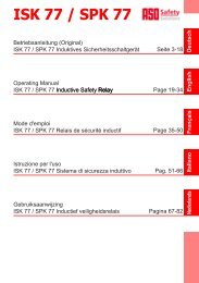
3.1 LED - indicators<br />
Led indicators for the contactors<br />
Led indicator for the safety contact edges<br />
Led indicators for the self-test<br />
6 7 8 9<br />
10<br />
1<br />
2<br />
3<br />
J2<br />
4 5<br />
LED 1 Release contactor switched<br />
LED 2 Contactor for OPENING direction switched<br />
LED 3 Contactor for CLOSING direction switched<br />
LED 4 lights, if the safety contact edge(s) for the<br />
OPENING direction is (are) OK<br />
LED 5 lights, if the safety contact edge(s) for the<br />
CLOSING direction is (are) OK<br />
LED 6 Self-test failing<br />
LED 7 Performing self-test step1 OPENING direction<br />
LED 8 Performing self-test step2 OPENING direction<br />
LED 9 Performing self-test step1 CLOSING direction<br />
LED 10 Performing self-test step2 CLOSING direction
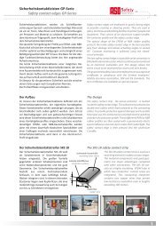
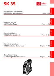
4. Electrical connection / Functional description<br />
For safety reasons the electrical installation is only to accomplished from a qualified electrical<br />
personal.<br />
The opening of the gate-controller is only permitted with switched off power supply. For the<br />
disconnection of the power supply a main power switch or the use of a CEE plug is to be<br />
planned. The main power switch or the power supply plug must be easily accessible.<br />
The points specified under the section - Important <strong>Safety</strong> Notes - are to be considered.<br />
The close installation of signal- <strong>and</strong> electric power-lines should be avoided as far as possible.<br />
All lines are to be dimensioned according to the capacity.<br />
For a simply attaching of the individual wires the clamps 5 to 24 are pluggable.<br />
The used stage nipple cable insertion may only cut to the stage, so that the insertion of the cable corresponds<br />
to the IP 54 protection against water <strong>and</strong> foreign objects.<br />
Damaged stage nipples must be exchanged immediately against intact.<br />
Overview connectors<br />
Supply Voltage connectors<br />
Motor connectors<br />
Light connectors<br />
Brake connectors<br />
Control switches connectors<br />
Light barrier connectors<br />
<strong>Safety</strong> device connectors<br />
Limit switches connectors<br />
Supply Voltage<br />
3 x 400 V 50 Hz<br />
M<br />
Light<br />
Brake<br />
A1 A2<br />
A3<br />
A4<br />
L1 L2 L3 N<br />
U V W<br />
F1 2AT<br />
Radio<br />
Control<br />
<strong>ATC</strong> <strong>100</strong><br />
5 6 7 8 9 10 11 12 13 14 15 16 17 18 19 20 21 22 23 24<br />
5 6 7 8 9 10 11 12 13 14 15 16 17 18 19 20 21 22 23 24<br />
STOP<br />
STOP<br />
Open<br />
Closed<br />
Impuls<br />
Com<br />
Com<br />
GND<br />
OUT<br />
+24V<br />
Closing<br />
Direction<br />
LS<br />
ISK<br />
Coil Core<br />
SKL<br />
8,2kΩ<br />
Opening<br />
Direction<br />
SKL<br />
8,2kΩ<br />
Closing<br />
Direction<br />
+24V<br />
GND<br />
OP<br />
CL<br />
Limit Switch<br />
1<br />
2<br />
3<br />
4 5<br />
ISK<br />
7
8<br />
<strong>Gate</strong> <strong>Controller</strong> <strong>ATC</strong> <strong>100</strong><br />
4.1 Mains voltage / Motor connection<br />
The <strong>ATC</strong> <strong>100</strong> allows the optional connection of 400 V - three-phase motors or 230 V one-phase motors. To<br />
the connection diagrams illustrated here the respective connection diagrams of the motor manufacturer<br />
are also to be considered. With motors without internal motor protection a suitable motor protection is to<br />
be planned. <strong>Safety</strong> devices of the motor, like temperature rise protection, crank h<strong>and</strong>le switch etc., must<br />
be connected to the clamps STOP.<br />
4.1.1 Three-phase motor connection<br />
For the connection of a three-phase motor the supply voltage<br />
is to be connected to the clamps L1, L2, L3. For the internal<br />
supply voltage of the <strong>ATC</strong> <strong>100</strong> it is necessary to connect the<br />
neutral conductor to the clamp N. The electrical safeguarding<br />
of the supply voltage is to be planned external <strong>and</strong> may have<br />
an amount of max. 3 x 10A.<br />
With the initial start-up of the gate pay attention to the rotation<br />
direction of the motor (if necessary exchange the connections<br />
V <strong>and</strong> W).<br />
Supply Voltage<br />
3 x 400 V 50 Hz<br />
M<br />
PE-Clamps<br />
Wiring regulation<br />
In order to keep the safety class, the jackets of this cables, as represented in the drawings, must reach<br />
up to the corresponding connectors. The removing of the jackets to the cable-gl<strong>and</strong>s is not<br />
permissible.<br />
After wiring the cable-gl<strong>and</strong>s must be tightened firmly.<br />
Supply Voltage<br />
3 x 400 V 50 Hz<br />
M<br />
Light<br />
Brake<br />
A1 A2 A3 A4<br />
F1 2AT<br />
Radio<br />
Control<br />
<strong>ATC</strong> <strong>100</strong><br />
5 6 7 8 9 10 11 12 13 14 15 16 17 18 19 20 21 22 23 24<br />
5 6 7 8 9 10 11 12 13 14 15 16 17 18 19 20 21 22 23 24<br />
STOP<br />
Supply Voltage<br />
3 x 400 V 50 Hz<br />
L1 L2 L3 N U V W<br />
STOP<br />
Open<br />
Closed<br />
Impuls<br />
Com<br />
Com<br />
GND<br />
OUT<br />
+24V<br />
Closing<br />
Direction<br />
LS<br />
SKL<br />
SKL<br />
8,2kΩ 8,2kΩ<br />
ISK<br />
Coil Core<br />
Opening<br />
Direction<br />
Closing<br />
Direction<br />
+24V<br />
GND<br />
OP<br />
CL<br />
Limit Switch<br />
1<br />
2<br />
3<br />
4 5<br />
ISK<br />
Supply Voltage<br />
3 x 400 V 50 Hz<br />
Light<br />
F1 2AT<br />
L1 L2 L3 N<br />
Radio<br />
Control<br />
<strong>ATC</strong> <strong>100</strong><br />
5 6 7 8 9 10 11 12 13 14 15 16 17 18 19 20 21 22 23 24<br />
STOP<br />
Motor<br />
A1 A2 A3 A4<br />
U V W<br />
5 6 7 8 9 10 11 12 13 14 15 16 17 18 19 20 21 22 23 24<br />
STOP<br />
Open<br />
Closed<br />
Impuls<br />
Com<br />
Com<br />
GND<br />
OUT<br />
+24V<br />
Closing<br />
Direction<br />
LS<br />
SKL<br />
SKL<br />
8,2kΩ 8,2kΩ<br />
ISK<br />
Coil Core<br />
Opening<br />
Direction<br />
Closing<br />
Direction<br />
+24V<br />
GND<br />
OP<br />
CL<br />
Limit Switch<br />
1<br />
2<br />
3<br />
L1<br />
L2<br />
L3<br />
N<br />
U<br />
V<br />
W<br />
4 5<br />
ISK
4.1.2 One-phase motor connection<br />
For the connection of a one-phase motor the supply voltage<br />
is to be connected to the clamps L1,N. The electrical<br />
safeguarding of the supply voltage is to be planned external<br />
<strong>and</strong> may have an amount of max. 10A.<br />
With the initial start-up of the gate pay attention to the rotation<br />
direction of the motor (if necessary exchange the connections<br />
V <strong>and</strong> W). Connect the neutral conductor of the motor to the<br />
clamp U. Additionally a bridge has to be inserted between L3<br />
<strong>and</strong> N.<br />
Supply Voltage<br />
3 x 400 V 50 Hz<br />
M<br />
Light<br />
Brake<br />
A1 A2 A3 A4<br />
F1 2AT<br />
Radio<br />
Control<br />
<strong>ATC</strong> <strong>100</strong><br />
5 6 7 8 9 10 11 12 13 14 15 16 17 18 19 20 21 22 23 24<br />
5 6 7 8 9 10 11 12 13 14 15 16 17 18 19 20 21 22 23 24<br />
STOP<br />
Supply Voltage<br />
230 V AC 50 Hz<br />
L1 L2 L3 N U V W<br />
STOP<br />
Open<br />
Closed<br />
Impuls<br />
Com<br />
Com<br />
GND<br />
OUT<br />
+24V<br />
Closing<br />
Direction<br />
LS<br />
SKL<br />
SKL<br />
8,2kΩ 8,2kΩ<br />
ISK<br />
Coil Core<br />
Opening<br />
Direction<br />
Closing<br />
Direction<br />
+24V<br />
GND<br />
OP<br />
CL<br />
Limit Switch<br />
1<br />
2<br />
3<br />
4 5<br />
ISK<br />
Supply Voltage<br />
3 x 400 V 50 Hz<br />
Supply Voltage<br />
230 V 50 Hz<br />
Light<br />
F1 2AT<br />
L1 L2 L3 N<br />
Radio<br />
Control<br />
M<br />
PE-Clamps<br />
Wiring regulation<br />
In order to keep the safety class, the jackets of this cables, as represented in the drawings, must reach<br />
up to the corresponding connectors. The removing of the jackets to the cable-gl<strong>and</strong>s is not<br />
permissible.<br />
After wiring the cable-gl<strong>and</strong>s must be tightened firmly.<br />
<strong>ATC</strong> <strong>100</strong><br />
5 6 7 8 9 10 11 12 13 14 15 16 17 18 19 20 21 22 23 24<br />
STOP<br />
Motor<br />
A1 A2 A3 A4<br />
U V W<br />
5 6 7 8 9 10 11 12 13 14 15 16 17 18 19 20 21 22 23 24<br />
STOP<br />
Open<br />
Closed<br />
Impuls<br />
Com<br />
Com<br />
GND<br />
OUT<br />
+24V<br />
Closing<br />
Direction<br />
LS<br />
SKL<br />
SKL<br />
8,2kΩ 8,2kΩ<br />
ISK<br />
Coil Core<br />
Opening<br />
Direction<br />
Closing<br />
Direction<br />
+24V<br />
GND<br />
C<br />
OP<br />
CL<br />
Limit Switch<br />
1<br />
2<br />
3<br />
L1<br />
L2<br />
L3<br />
N<br />
U<br />
V<br />
W<br />
4 5<br />
ISK<br />
9
10<br />
<strong>Gate</strong> <strong>Controller</strong> <strong>ATC</strong> <strong>100</strong><br />
4.2 Relay outputs (potential free)<br />
A warning-light (flashing-, round about light, etc.), which lights<br />
or flashes while opening or closing the gate, can be<br />
connected to the clamps A1, A2. Furthermore the output for<br />
the activation of a light or a brake can be used.<br />
An individual parametrizable brake can be attached to the<br />
clamps A3, A4.<br />
Supply Voltage<br />
3 x 400 V 50 Hz<br />
M<br />
Light<br />
Brake<br />
A1 A2 A3 A4<br />
F1 2AT<br />
Radio<br />
Control<br />
<strong>ATC</strong> <strong>100</strong><br />
5 6 7 8 9 10 11 12 13 14 15 16 17 18 19 20 21 22 23 24<br />
5 6 7 8 9 10 11 12 13 14 15 16 17 18 19 20 21 22 23 24<br />
STOP<br />
L1 L2 L3 N U V W<br />
STOP<br />
Open<br />
Closed<br />
Impuls<br />
Com<br />
Com<br />
GND<br />
OUT<br />
+24V<br />
Closing<br />
Direction<br />
LS<br />
Licht<br />
SKL<br />
SKL<br />
8,2kΩ 8,2kΩ<br />
ISK<br />
Coil Core<br />
Opening<br />
Direction<br />
Closing<br />
Direction<br />
+24V<br />
GND<br />
OP<br />
CL<br />
Limit Switch<br />
1<br />
2<br />
3<br />
4 5<br />
ISK<br />
Supply Voltage<br />
3 x 400 V 50 Hz<br />
M<br />
Light<br />
Brake<br />
F1 2AT<br />
U V W<br />
Radio<br />
Control<br />
<strong>ATC</strong> <strong>100</strong><br />
1<br />
2<br />
3<br />
4<br />
Relay 1<br />
Relay 3<br />
Wiring regulation<br />
If the potential free contacts of the relay outputs are connected to a dangerous voltage, the jackets of these<br />
cables must reach up to the corresponding connectors in order to keep the safety class. The removing of<br />
the jackets to the cable-gl<strong>and</strong>s is not permissible.<br />
After wiring the cable-gl<strong>and</strong>s must be tightened firmly.<br />
A1 A2 A3 A4<br />
5 6 7 8 9 10 11 12 13 14 15 16 17 18 19 20 21 22 23 24<br />
STOP<br />
L1 L2 L3 N<br />
5 6 7 8 9 10 11 12 13 14 15 16 17 18 19 20 21 22 23 24<br />
STOP<br />
Open<br />
Closed<br />
Impuls<br />
Com<br />
Com<br />
GND<br />
OUT<br />
+24V<br />
Closing<br />
Direction<br />
LS<br />
Bremse<br />
SKL<br />
SKL<br />
8,2kΩ 8,2kΩ<br />
ISK<br />
Coil Core<br />
Opening<br />
Direction<br />
Closing<br />
Direction<br />
+24V<br />
GND<br />
OP<br />
CL<br />
Limit Switch<br />
1<br />
2<br />
3<br />
4 5<br />
ISK
4.3 STOP inputs<br />
The STOP-inputs are inputs without a safety-related-function.<br />
They are for the monitoring of STOP-signal generator (e.g.<br />
STOP-button etc.).<br />
The two inputs are internally switched in series. If a stop is<br />
released, this causes an immediate stop in both directions<br />
of travel <strong>and</strong> the message "STOP" appears in the display.<br />
The STOP-chain is active in every program step, except the<br />
gate end position. By the STOP-instructions all stored<br />
instructions (e.g. automatic closing etc.) are deleted.<br />
Therefore a new initial instruction must possibly be given<br />
after clearance of the malfunction.<br />
If an input <strong>and</strong>/or both inputs are not connected they are to<br />
be bridged accordingly. If there are more than two STOPinputs<br />
needed the opener circles of the signal generators<br />
have to be switched in series.<br />
4.4 Control switch inputs<br />
Connect to the clamps 8 to 12 the control switches (normally<br />
open contacts) for the Opening, Closing <strong>and</strong> Impuls. These<br />
control switches can be implemented as switches, keyoperated<br />
push buttons, code lock or extern radio controller.<br />
Depending of the settings for "Impuls" the impuls input<br />
initializes the instruction sequence "open-stop close-stop<br />
..."<strong>and</strong>/or "open, close, open ...". In the end positions of the<br />
gate the impuls will initiate the corresponding moving of the<br />
gate.<br />
4.5 Light-barrier inputs<br />
Inputs for a light barrier, which is active in the closing<br />
movement of the gate. Dependent on the settings an initiation<br />
of the light barrier in the closing movement causes a STOP<br />
with short or STOP with full reversion. Contrary to the full<br />
reversion the automatic closing will be deleted with the short<br />
reversion. If several light barriers are installed, the appropriate<br />
light barrier contacts are to be switched in series.<br />
If the input is not used the inputs 14, 15 are to be bridged<br />
accordingly.<br />
With activation of the "secondary-time" the function for quick<br />
closing after crossing the light barrier can be realized in the<br />
"automatic-mode". Instead of the adjusted open-time the<br />
adjusted secondary-time is used as a new open-time after<br />
crossing the light barrier..<br />
STOP<br />
STOP<br />
Open<br />
8 8<br />
Close<br />
9 9<br />
Impuls<br />
10 10<br />
Com<br />
11 11<br />
Com 12 12<br />
LS<br />
Closing<br />
Direction LS<br />
GND<br />
OUT<br />
+24V<br />
5<br />
6<br />
7<br />
13<br />
14<br />
15<br />
5<br />
6<br />
7<br />
13<br />
14<br />
15<br />
or bridge<br />
or bridge<br />
11
12<br />
<strong>Gate</strong> <strong>Controller</strong> <strong>ATC</strong> <strong>100</strong><br />
4.6 <strong>Safety</strong> contact edges connection<br />
Stationary safety contact edges<br />
The direction depending monitoring of the stationary safety<br />
contact edges takes place directly on the <strong>ATC</strong> <strong>100</strong>. The<br />
contact edges working against the driving direction have no<br />
influence to the program sequence. If the automatic closing<br />
is activated an actuating of the contact edges will reset the<br />
automatic closing till the next start-up signal.<br />
Not used inputs must be terminated with a 8,2 kΩ resistor.<br />
Travelling safety contact edges<br />
The direction depending monitoring of the safety contact edges<br />
travelling with the gate (sliding gates applications) takes<br />
place via the optionally plug-on inductive safety system ISK<br />
70-75 electronic. The contact edges working against the<br />
driving direction have no influence to the program sequence.<br />
If the automatic closing is activated an actuating of the<br />
contact edges will reset the automatic closing up to the next<br />
start-up signal. Please take the detailed description <strong>and</strong> the<br />
assembly instruction for the ISK-system from the current<br />
ISK documentation.<br />
ISK<br />
Coil Core<br />
<strong>Safety</strong> Edge<br />
Opening<br />
<strong>Safety</strong> Edge<br />
Closing<br />
For gates where no ISK modules is needed (roller-, revolving-, sectional-doors etc.) the function of the ISK-system<br />
can be deactivated. For this the jumper J2 is to be bridged.<br />
The installation without safety contact edges <strong>and</strong>/or without ISK-system may only be used on gate-systems<br />
which have their own <strong>and</strong> to the latest st<strong>and</strong>ards confirming safety devices. <strong>Gate</strong> systems without safety<br />
devices may only operated in manual mode to prevent severe injuries.<br />
The liability of the manufacturer is terminated with neglect or deliberate abuse.<br />
4.7 Limit switch inputs<br />
The limit switches OPEN (Limit Switch OP) <strong>and</strong> the limit<br />
switch CLOSE (Limit Switch CL) are monitored permanently<br />
<strong>and</strong> are stringently necessary for the allocation of the actual<br />
end position. The limit switches can be implemented e.g. as<br />
rolling- or inductive limit switch (normally close contact).<br />
If end position OPEN <strong>and</strong> end position CLOSE is detected<br />
at the same time the program stops. The signal "ERROR<br />
end positions" is indicated in the display.<br />
4.8 Power supply output 24 V<br />
For the supply of external consumers the <strong>ATC</strong> <strong>100</strong> provides<br />
a power supply output with 24V DC ±15%.<br />
This 24 V power supply output may be loaded with<br />
max. 250 mA..<br />
+24V<br />
0V<br />
8,2kΩ 8,2kΩ<br />
Limit Switch<br />
SKL<br />
SKL<br />
+24V<br />
GND<br />
16<br />
17<br />
18<br />
19<br />
20<br />
OP<br />
CL<br />
16<br />
17<br />
18<br />
19<br />
20<br />
21<br />
22<br />
23<br />
24<br />
21<br />
22<br />
24V DC for ext. consumer<br />
(max. 250 mA)
5. Plug-on modules<br />
All sockets on the <strong>ATC</strong> <strong>100</strong> are particularly intended<br />
for the described plug-on modules. The inserting of<br />
other plug-on modules can damage or destroy the<br />
<strong>ATC</strong> <strong>100</strong> controller as well as the plug-on modules.<br />
The plug-on modules may be inserted <strong>and</strong>/or taken<br />
off only in switched off condition of the control. The<br />
respective plug-on modules can be only inserted<br />
on the appropriate socket of the <strong>ATC</strong> <strong>100</strong> <strong>and</strong> only<br />
in one direction. Taking off a plug-on module from<br />
it's socket is facilitated by mutual tilting of the<br />
appropriate module.<br />
5.1 Control module<br />
The pluggable control module serves the parametrization,<br />
the visualization of the control sequences <strong>and</strong> the<br />
diagnosis in case of an error.<br />
The controller can be operated either with or without the<br />
control module. The operability of the controller is<br />
identical in both cases. With this the pluggable control<br />
module offers an effective protection from manipulation<br />
or unauthorized access.<br />
The function range of the controller is not limited by the<br />
missing control module.<br />
5.2 Additional modules (optionally available)<br />
Please pay attention to the individual<br />
documentations of the additional modules.<br />
5.2.1 Inductive safety system ISK 70-75<br />
With the additional module ISK 70-75 (sliding gate<br />
application) up to two travelling safety contact edge<br />
circuits can be connected <strong>and</strong> monitored direction<br />
depending. These safety contact edges at the gate wing<br />
are monitored by the inductive safety system wearoutfree<br />
<strong>and</strong> without mechanical stress. The contact edge<br />
working against the direction has no influence to the program<br />
sequence. The semiconductor outputs are linked<br />
with the soft- <strong>and</strong> hardware of the control.<br />
The installation on a sliding gate<br />
application without ISK-system may only<br />
be used on gate-systems which have<br />
their own <strong>and</strong> to the latest st<strong>and</strong>ards confirming<br />
safety devices. <strong>Gate</strong> systems without safety<br />
devices may only operated in manual mode to<br />
prevent severe injuries.<br />
The liability of the manufacturer is terminated<br />
with neglect or deliberate abuse.<br />
5.2.2 Time switch ZU 3<br />
With the integration of the pluggable time switch a daydependent<br />
automation of the gate system is possible.<br />
The time switch contains the following functions:<br />
• Up to 8 program sequences per day (Rush-Hour)<br />
• Program sequences can be copied to different days<br />
• smallest switching time is 1 minute<br />
• Digital display of clock-time <strong>and</strong> weekdays<br />
• Summer-/winter time conversion alternatively by h<strong>and</strong><br />
or automatically<br />
5.2.3 Radio control<br />
The single-channel radio controller works with 433MHz.<br />
Depending of the settings "Impuls", the radio-impulse<br />
initializes the instruction sequence "Open-Stop- Close-<br />
Stop ..." resp. "Open,Close,Open ...". In the end positions<br />
of the gate the radio impulse will initiate the corresponding<br />
moving of the gate.<br />
• Adjusting the radio receiver<br />
- Set the DIP-switch of the radio receiver to individual<br />
code<br />
- Select the key allocation of the receiver:<br />
1-Instruction h<strong>and</strong>-transmitter:<br />
insert jumper J1 und J2<br />
2-Instruction h<strong>and</strong>-transmitter:<br />
insert only jumper J2 → first (left) key selected<br />
insert only jumper J1 → second (right) key selected<br />
3-Instruction h<strong>and</strong>-transmitter:<br />
insert jumper J1 <strong>and</strong> J2 → first key selected<br />
insert only jumper J2 → second key selected<br />
only jumper J1 inserted → third key selected<br />
4-Instruction h<strong>and</strong>-transmitter:<br />
insert jumper J1<strong>and</strong> J2 → first key selected<br />
only jumper J2 inserted → second key selected<br />
only jumper J1 inserted → third key selected<br />
no jumper inserted → fourth key selected<br />
• Adjusting the h<strong>and</strong> transmitter<br />
- Adjust the DIP-switch of the h<strong>and</strong>-transmitter<br />
accordingly to the settings of the radio-receiver.<br />
13
14<br />
<strong>Gate</strong> <strong>Controller</strong> <strong>ATC</strong> <strong>100</strong><br />
6. Program settings<br />
In this description of the settings a maximum<br />
configuration of the system is presupposed. If a<br />
component is missing in the system the appropriate<br />
subfunction of the controller is inactive (poss. insert<br />
bridge).<br />
The display of the <strong>ATC</strong><strong>100</strong> control module is implemented<br />
as a two-line display. The upper line generally indicates<br />
the mode of operation. The second line indicates the<br />
selected function depending upon the mode of operation.<br />
In the mode automatic the conditions of the gate system<br />
are displayed here.<br />
Menu select button 8<br />
function button 9<br />
close (-) button 10<br />
open (+) button<br />
With the button MENU SELECT 4 modes of operation<br />
can be adjusted. By actuating the button (approx. 2 sec.)<br />
the individual modes of operation can be selected in<br />
sequence.<br />
AUTOMATIK<br />
TOTMANNBETRIEB<br />
EINGABE<br />
DIAGNOSE<br />
In the different modes of operation the buttons<br />
CLOSE(-) <strong>and</strong> OPEN(+) have different functions.<br />
6.1 AUTOMATIC<br />
The button CLOSE(-) <strong>and</strong> OPEN(+) have no function.<br />
6.2 MANUAL MODE<br />
In the manual mode the drive can be opened with the<br />
button OPEN (+) <strong>and</strong> be closed with the button<br />
CLOSE(-). (with faulty or missing safety devices no<br />
manual mode operation is possible).<br />
11<br />
6.3 ADJUST<br />
To change the <strong>ATC</strong> <strong>100</strong> settings the button MENU<br />
SELECT <strong>and</strong> the button FUNCTION have to be pressed<br />
at the same time (approx. 2 sec.) to reach the adjustmenu.<br />
The parameter to be changed can be selected by pressing<br />
the button FUNCTION (the individual parameters are<br />
indicated "rolling wise"). The appropriate selected<br />
parameter can be adjusted by pressing the button<br />
OPEN(+) or CLOSE(-).<br />
If all parameters are adjusted in this way, press the buttons<br />
MENU SELECT <strong>and</strong> FUNCTION to leave the adjustmenu.<br />
If no button is actuated in the adjust-mode for 90<br />
sec., all adjusted parameters will be saved <strong>and</strong> the<br />
controller switches to the MANUAL MODE.<br />
With the switch MENU SELECT the mode "AUTOMATIC"<br />
can be selected again.<br />
The parameters appear in the following sequence <strong>and</strong><br />
have the functions as described.<br />
• LCD<br />
Deutsch / English / Francais Pre-setting: Deutsch<br />
Language setting for control module.<br />
• Run Time<br />
1 up to 240 sec. Pre-setting: 120 sec.<br />
In order to protect drive <strong>and</strong> gate mechanics the run time is<br />
monitored during the opening- <strong>and</strong> closing phase. If the<br />
appropriate limit switch is not reached in the programmed<br />
time the controller stops. If this happens the control module<br />
displays ERROR run time. The adjusted run time should be<br />
selected 10 sec. longer than the maximum gate run time.<br />
• OPEN TIME<br />
0 up to 600 sec. Pre-setting: 0 sec.<br />
The counting of time begins after reaching the limit-switch<br />
OPEN. After expiring this time the advance warning time<br />
begins followed by the automatic closing of the gate.<br />
The automatic closing is deactivated if the opening time is<br />
adjusted to 0.<br />
Automatic closing can also be prevented on the<br />
hardware side. For this the Jumper 1 is to be<br />
removed.<br />
• PRE-WARN. (Pre-Warning)<br />
0 up to 120 sec. Pre-setting: 0 sec.<br />
(Applicable only in closing-movement)<br />
With setting 0 the gate starts immediately after a moving<br />
instruction. With adjusted time the pre-warning is started<br />
<strong>and</strong> the gate only starts to run after expiration of the adjusted<br />
time.
• REV. TIME (Reversal-Time)<br />
0,1 up to 2,0 sec. Pre-setting: 0,5 sec.<br />
Delay-time before changing moving-direction.<br />
• 2ND Time<br />
0 up to 60 sec. Pre-setting: 0 sec.<br />
With activation of the "2nd time" the function of quick closing<br />
after crossing the light barrier can be realized in the<br />
"automatic closing" mode. Instead of the adjusted open time<br />
the 2nd time is used as the new open time after crossing<br />
the light barrier.<br />
• Relay Light<br />
MOD 1,2,3,4 or 5 Pre-setting: MOD 1<br />
Relay output to control a light, a warning light or a brake at<br />
the gate.<br />
MOD 1: Continuous light funct. as long as gate is in motion<br />
MOD 2: Light control after opening-instruction for 3 min.<br />
MOD 3: Brake function, relay switched if gate stops<br />
MOD 4: Failure light, lights so long as the failure is present<br />
MOD 5: Failure light, like MOD 4 however with 20 sec.<br />
switch -off delay<br />
• EDGE CL (<strong>Safety</strong> contact edge closing direction)<br />
MOD 1 or 2 Pre-setting: MOD 2<br />
This parameter specifies the reaction of the controller if the<br />
safety contact edge is activated in the closing movement.<br />
MOD 1: STOP plus short reversion 1,5 sec.<br />
MOD 2: STOP plus full reversion<br />
• EDGE OP (<strong>Safety</strong> contact edge opening direction)<br />
MOD 1 or 2 Pre-setting: MOD 1<br />
This parameter specifies the reaction of the controller if the<br />
safety contact edge is activated in the opening movement.<br />
MOD 1: STOP plus short reversion 1,5 sec.<br />
MOD 2: STOP plus full reversion<br />
• LIGHT B. CL (Light barrier closing movement)<br />
MOD 1 or 2 Pre-setting: MOD 2<br />
This parameter specifies the reaction of the controller if the<br />
light barrier is interrupted (closing movement).<br />
MOD 1: STOP plus short reversion 1,5 sec.<br />
MOD 2: STOP plus full reversion<br />
• BRAKE:<br />
MOD 1 or 2 Pre-setting: MOD 2<br />
This parameter specifies how the motor-brake is controlled.<br />
MOD 1: Relay is activated if motor st<strong>and</strong>s<br />
MOD 2: Relay is activated if motor runs<br />
MOD 3: Relay is activated for 3 sec. if motor st<strong>and</strong>s<br />
MOD 4: Relay is activated for 3sec. if motor runs<br />
• IMPULS MOD<br />
MOD 1 or 2 Pre-setting: MOD 1<br />
Specifies the function of the impulse-input.<br />
MOD 1: open/stop/close/stop ...<br />
MOD 2: open/close/open ...<br />
• TIME SWIT. (Time Switch)<br />
MOD 1 or 2 Pre-setting: MOD 1<br />
Specifies the function of the time switch.<br />
The operation of the gate is at anytime possible because<br />
the clock only prevents automatic closing.<br />
MOD 1: Opening of the gate by opening-button, after that<br />
the clock keeps the gate open.<br />
MOD 2: Opening of the gate by clock, after that the clock<br />
keeps the gate open.<br />
15
16<br />
<strong>Gate</strong> <strong>Controller</strong> <strong>ATC</strong> <strong>100</strong><br />
6.4 DIAGNOSIS<br />
In the mode diagnosis in each case 2 inputs are indicated<br />
in the display as a check of the conditions. The inputs<br />
are indicated as full-text with associated ON or OFF.<br />
Using the switches open (+) <strong>and</strong> close (-) changes to<br />
the next pair of inputs.<br />
In case of malfunction all inputs can be checked very<br />
easy by this indication without using measurement<br />
instruments. By a further pressure of the button<br />
FUNCTION the next mode of operation is reached.<br />
Indicated operating conditions<br />
EDGE OP (<strong>Safety</strong> contact edge opening direction)<br />
Displays the operating conditions of the safety contact edges<br />
for the opening direction.<br />
EDGE OP On<br />
<strong>Safety</strong> contact edges are wired <strong>and</strong> no operation or<br />
malfunction is present.<br />
EDGE OP Off<br />
<strong>Safety</strong> contact edges are not wired or an operation or a<br />
malfunction is present.<br />
EDGE CL (<strong>Safety</strong> contact edge closing direction)<br />
Displays the operating conditions of the safety contact edges<br />
for the closing direction..<br />
EDGE CL On<br />
<strong>Safety</strong> contact edges are wired <strong>and</strong> no operation or<br />
malfunction is present.<br />
EDGE CL Off<br />
<strong>Safety</strong> contact edges are not wired or an operation or a<br />
malfunction is present.<br />
AUTO RUN (automatic closing of the gate)<br />
Displays whether the automatic closing of the gate is<br />
activated or not. The automatic closing of the gate can be<br />
disabled over the Jumper J1.<br />
AUTO RUN On<br />
Automatic closing activated<br />
AUTO RUN Off<br />
Automatic closing not activated<br />
Light B. CL<br />
Displays the operating conditions of the passage light barrier<br />
for the closing movement.<br />
Light B. CL On<br />
Passage light barrier installed <strong>and</strong> light beam is not<br />
interrupted.<br />
Light B. CL Off<br />
Passage light barrier not installed or light beam is not<br />
interrupted.<br />
LIMIT SW OP (limit switch for opened gate)<br />
Displays the operating conditions of the limit switch for<br />
opened gate position.<br />
LIMIT SW OP On<br />
Limit switch wired correctly <strong>and</strong> is not operated<br />
LIMIT SW OP Off<br />
Limit switch is not wired correctly or is operated<br />
LIMIT SW CL (limit switch for closed gate)<br />
Displays the operating conditions of the limit switch for<br />
closed gate position.<br />
LIMIT SW CL On<br />
Limit switch wired correctly <strong>and</strong> is not operated<br />
LIMIT SW CL Off<br />
Limit switch is not wired correctly or is operated<br />
SWITCH OPEN (Switch/button for OPEN-instruction)<br />
Displays the operating condition of the switch/button for the<br />
OPEN-instruction.<br />
SWITCH OPEN On<br />
Switch/button is operated<br />
SWITCH OPEN Off<br />
Switch/button is not operated<br />
SWITCH CLOSE (Switch/button for CLOSE-instruction)<br />
Displays the operating condition of the switch/button for the<br />
CLOSE-instruction.<br />
SWITCH CLOSE On<br />
Switch/button is operated<br />
SWITCH CLOSE Off<br />
Switch/button is not operated<br />
STOP<br />
Displays the operating condition of the stop chain. To the<br />
STOP chain belongs e.g. stop tracer, emergency stop<br />
pushbutton etc., which are switched into row.<br />
STOP On<br />
Stop-chain is wired correctly respectively no device is<br />
operated or has triggered.<br />
STOP Off<br />
Stop-chain is not wired correctly respectively a device is<br />
operated or has triggered.<br />
IMPULS<br />
Displays the operating condition of the impuls switch/button<br />
Impuls On<br />
Switch/button is operated<br />
Impuls Off<br />
Switch/button is not operated<br />
TIME SWIT.<br />
Displays the operating condition of the time switch.<br />
TIME SWIT. On<br />
Time switch gives an instruction to the controller.<br />
TIME SWIT. Off<br />
Time switch doesn't give an instruction to the controller.<br />
CYCLE<br />
The counted cycles which are executed so far by the controller<br />
are indicated here.
7. Jumper settings:<br />
With the 2 jumpers on the board general functions can<br />
be adjusted.<br />
• Jumper J1: automatic closing<br />
J1 open: automatic closing deactivated<br />
J1 bridged: automatic closing activated<br />
• Jumper J2: ISK-<strong>Safety</strong> system<br />
J2 open: ISK-<strong>Safety</strong> system activated<br />
J2 bridged: ISK-<strong>Safety</strong> system deactivated<br />
8. Article numbers<br />
<strong>ATC</strong><strong>100</strong> compl. with enclosure, control module 302030<br />
<strong>ATC</strong><strong>100</strong> only electronic without controle module302031<br />
Control modul for <strong>ATC</strong><strong>100</strong> 302033<br />
Enclosure for <strong>ATC</strong><strong>100</strong> 302034<br />
Plug-on module ISK 70-75 204160<br />
Plug-on module ISK 70-75 204162<br />
in the set with SPK9 <strong>and</strong> SPK 12<br />
Time switch ZU 3 550103<br />
Radio receiver HE single channel<br />
with antenna<br />
515110<br />
H<strong>and</strong> transmitter HE single-channel 514001<br />
H<strong>and</strong> transmitter HE dual-channel 514002<br />
H<strong>and</strong> transmitter HE quad-channel 514004<br />
9. Enclosure<br />
ABS-Enclosure with cable gl<strong>and</strong>s <strong>and</strong> stage nipple cable<br />
insertions.<br />
9.1 Mounting of the enclosure<br />
Before mounting the controller is to be examined for<br />
possible transportation or other damages. If the electronic<br />
or the enclosure is damaged the controller may not been<br />
installed or taken in operation.<br />
After removing the cover the enclosure can be fixed with<br />
four screws.<br />
Mounting on walls:<br />
Wood screws 4x40mm with 6mm dowel<br />
Mounting on the gate:<br />
Tapping screw 4x20mm or machine screw M4x20mm<br />
The <strong>ATC</strong> <strong>100</strong> is to be fastened professionally with all<br />
four screws to a suitable mounting place with even<br />
underground.<br />
The <strong>ATC</strong><strong>100</strong> is designed for a vertical mounting.<br />
In order to prevent infiltrating humidity through the cable<br />
gl<strong>and</strong>s, the enclosure should be installed in such a way<br />
that the cable gl<strong>and</strong>s point downwards.<br />
The weight of the controller of approx. 1,8kg should be<br />
absolutely considered with the choice of the mounting.<br />
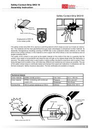
9.2 Enclosure dimensions<br />
160<br />
130<br />
Mounting holes<br />
4x 4,2 mm<br />
15<br />
75<br />
228<br />
90<br />
240<br />
275<br />
17
18<br />
<strong>Gate</strong> <strong>Controller</strong> <strong>ATC</strong> <strong>100</strong><br />
10. Technical data<br />
• Supply voltage<br />
UE 3 x 400 V 50/60Hz main power supply for<br />
three-phase drives<br />
UE 230 V 50/60Hz main power supply for<br />
one-phase drives<br />
I / I E Emax 65 mA / 107 mA current consumption<br />
P / Pmax 15 VA / 24,5 VA power consumption<br />
The maximum values are valid for the maximum<br />
configuration of the controller <strong>and</strong> the maximum supply<br />
of external 24V components.<br />
• External safeguarding<br />
F max. 10A<br />
B<br />
• Internal safeguarding<br />
Fi T 2A / 250 V glass tube fuse<br />
5x20mm<br />
• Supply outputs 24 V DC<br />
U 24 V DC ± 15%<br />
Out24V<br />
I 250 mA<br />
Outmax24V<br />
P 6 W<br />
Outmax24V<br />
To guarantee the correct function of the controller the<br />
listed maximum values may not be exceeded in any case.<br />
• Motor reversing contactor<br />
PSmax230V 2,2 KW max. contactor output<br />
with 230 V one-phase<br />
drives<br />
PSmax400V • Relays<br />
4KW with 400 V three-phase<br />
drives<br />
UREL 250 V~ max. switching voltage<br />
IREL 2,5 A~ max. switching current<br />
• Switching times <strong>Safety</strong> device<br />
TA ≤ 25 ms STOP initiated → contactor open<br />
TA ≤ 30 ms ISK initiated → contactor open<br />
• Protection class<br />
IP 54 Enclosure with cable gl<strong>and</strong>s/stagenipples<br />
• Weight 1,8 kg<br />
• Temperature range -10° to +55° C<br />
• Store temperature -20° to +70° C<br />
• Approvals<br />
EN 12453 - "<strong>Safety</strong> in use of power operated doors/gates"<br />
EN 12978 - "<strong>Safety</strong> devices for power operated gates"
Antriebs- und Steuerungstechnik<br />
Am Grarock 8 • D-33154 Salzkotten<br />
Tel.: 0 52 58/93 27-0 • Fax: 0 52 58/34 48<br />
www.asogmbh.de • e-mail: info@asogmbh.de<br />
Technical Data Version 1.5:<br />
St<strong>and</strong> 26.08.2005 Subject to change without prior notice