ISK 77 / SPK 77 - ASO Safety
ISK 77 / SPK 77 - ASO Safety
ISK 77 / SPK 77 - ASO Safety

Create successful ePaper yourself
Turn your PDF publications into a flip-book with our unique Google optimized e-Paper software.
<strong>ISK</strong> <strong>77</strong> / <strong>SPK</strong> <strong>77</strong><br />
Betriebsanleitung (Original)<br />
<strong>ISK</strong> <strong>77</strong> / <strong>SPK</strong> <strong>77</strong> Induktives Sicherheitsschaltgerät Seite 3-18 Deutsch<br />
Operating Manual<br />
<strong>ISK</strong> <strong>77</strong> / <strong>SPK</strong> <strong>77</strong> Inductive Safet�� Safet�� Rela�� Rela�� Rela��<br />
Page 19-34 English<br />
Mode d'emploi<br />
<strong>ISK</strong> <strong>77</strong> / <strong>SPK</strong> <strong>77</strong> Relais de sécurité inductif Page 35-50 Français<br />
Istruzione per l'uso<br />
<strong>ISK</strong> <strong>77</strong> / <strong>SPK</strong> <strong>77</strong> Sistema di sicurezza induttivo Pag. 51-66 Italiano<br />
Gebruiksaanwijzing<br />
<strong>ISK</strong> <strong>77</strong> / <strong>SPK</strong> <strong>77</strong> Inductief veiligheidsrelais Pagina 67-82<br />
Nederlands
2<br />
Übergabedokumentation / Documentation / Documentation<br />
de datation / Documentazione di consegna / Documentatie<br />
Anlagenbeschreibung / Description / Description du système / Descrizione impianto /<br />
Beschrijving van de installatie<br />
Anlagenart / T��pe of plant / Sorte du s��stème / Tipo d’impianto / T��pe installatie<br />
Hersteller / Manufacturer / Fabricant / Produttore / Fabrikant<br />
Seriennummer / Serial number / Numéro de série / Numero di serie / Seriennummer<br />
Datum der Inbetriebnahme / Commissioning date / Date de mise en marche / Data della messa in<br />
funzione / Datum van de ingebruikname<br />
Aufstellort / Site of installation / Lieu de montage / Luogo d’installazione / Opstellingsplaats<br />
Verwendete Steuerung / Control unit / Commande utilisée / Centralina di comando adottata /<br />
Gebruikte besturing<br />
Zusatzkomponenten / Additional components / Composants supplémentaires / Componenti<br />
ausiliari / Bijkomende componenten<br />
Funktionsprüfung / Functional test / Contrôle de fonction / Controllo funzionale / Functiecontrole<br />
Sicherheitssensoren reagieren auf Betätigung / Safet�� sensor response to actuation /<br />
Le senseur de sécurité réagit à l’actionnement / Il sensore di sicurezza reagisce all’azionamento /<br />
Veiligheidssensor reageert op activering<br />
Sicherheitssensoren reagieren auf Zuleitungsunterbrechung / Safet�� sensor response to<br />
suppl�� line interruption / Le senseur de sécurité réagit à l’interruption de l’alimentation /<br />
Il sensore di sicurezza reagisce all’interruzione di collegamento Veiligheidssensor reageert<br />
op onderbreking van de toevoerleiding<br />
Name der ausführenden Firma / Owner / Nom de la société exécutrice / Nome della ditta<br />
esecutrice / Naam van de uitvoerende firma<br />
Name des Installateurs / Installer / Nom de l’installateur / Nome dell’installatore / Naam van de<br />
installateur<br />
Datum / Date / Date / Data / Datum Unterschrift / Signature / Signature / Firma /<br />
Handtekening<br />
ok<br />
ok
<strong>ISK</strong> <strong>77</strong> / <strong>SPK</strong> <strong>77</strong><br />
Induktives Sicherheitsschaltgerät<br />
1. Inhaltsverzeichnis<br />
1. Inhaltsverzeichnis . . . . . . . . . . . . . . . . . . . . . . . . . . . 3<br />
2. Allgemeine Sicherheitsbestimmungen und Schutzmaßnahmen . . .4<br />
3. Allgemeines und Funktionsbeschreibung . . . . . . . . . . . . . . . 5<br />
4. Bestimmungsgemäße Verwendung . . . . . . . . . . . . . . . . . . 5<br />
5. Verwendungsbeispiele . . . . . . . . . . . . . . . . . . . . . . . . 6<br />
5.1 <strong>ISK</strong> <strong>77</strong> mit passiver Übertragung der mitfahrenden Schaltleisten . . . . . . . . . 6<br />
5.2 <strong>SPK</strong> <strong>77</strong> mit feststehendem Spulenkern integriert. . . . . . . . . . . . . . . . . . 6<br />
6. Geräteübersicht . . . . . . . . . . . . . . . . . . . . . . . . . . . . 7<br />
6.1 Ausführungen . . . . . . . . . . . . . . . . . . . . . . . . . . . . . . . . . . . 7<br />
6.1.1 Gerätevariante <strong>ISK</strong> <strong>77</strong> . . . . . . . . . . . . . . . . . . . . . . . . . . . . 7<br />
6.1.2 Gerätevariante <strong>SPK</strong> <strong>77</strong>. . . . . . . . . . . . . . . . . . . . . . . . . . . . 7<br />
6.1.3 Variante F. . . . . . . . . . . . . . . . . . . . . . . . . . . . . . . . . . . 7<br />
6.1.4 Variante E . . . . . . . . . . . . . . . . . . . . . . . . . . . . . . . . . . 8<br />
6.1.5 Variante W . . . . . . . . . . . . . . . . . . . . . . . . . . . . . . . . . . 8<br />
6.1.6 Variante R . . . . . . . . . . . . . . . . . . . . . . . . . . . . . . . . . . 8<br />
6.1.7 Variante T. . . . . . . . . . . . . . . . . . . . . . . . . . . . . . . . . . . 8<br />
6.1.8 Variante D . . . . . . . . . . . . . . . . . . . . . . . . . . . . . . . . . . 8<br />
6.2 Signalanzeigen . . . . . . . . . . . . . . . . . . . . . . . . . . . . . . . . . . . 9<br />
6.3 Anschlussklemmen. . . . . . . . . . . . . . . . . . . . . . . . . . . . . . . 9-10<br />
7. Mechanische Befestigung . . . . . . . . . . . . . . . . . . . . . . 10<br />
7.1 .1 <strong>ISK</strong> <strong>77</strong> . . . . . . . . . . . . . . . . . . . . . . . . . . . . . . . . . . . . . . 11<br />
7.2 .2 <strong>SPK</strong> <strong>77</strong> . . . . . . . . . . . . . . . . . . . . . . . . . . . . . . . . . . . . . . 11<br />
8. Anschliessen der Signalgeber. . . . . . . . . . . . . . . . . . . . 11<br />
8.1 Anschluss am Spulenkern <strong>SPK</strong> 54 . . . . . . . . . . . . . . . . . . . . . . . . 11<br />
8.2 .2 Anschlussarten Anschlussarten am Spulenkern <strong>SPK</strong> <strong>SPK</strong> 54 54 . . . . . . . . . . . . . . . . . . . . . 11<br />
8.3 Anschluss von mehreren Signalgebern . . . . . . . . . . . . . . . . . . . . . 12<br />
9. Elektrische Inbetriebnahme . . . . . . . . . . . . . . . . . . . . . 12<br />
9.1 Voraussetzungen . . . . . . . . . . . . . . . . . . . . . . . . . . . . . . . . . 12<br />
9.2 .2 Elektrischer Anschluss . . . . . . . . . . . . . . . . . . . . . . . . . . . . . . 12<br />
9.3 Testung mit Beschaltungsmöglichkeiten. . . . . . . . . . . . . . . . . . . . . . 13<br />
9.4 .4 Besonderheiten Besonderheiten der Sicherheitshalbleiterausgänge (OSSD). (OSSD)<br />
. . . . . . . . . . 13<br />
9.5 Inbetriebnahme / Funktionsprüfung . . . . . . . . . . . . . . . . . . . . . . . . 14<br />
10. Fehlerdiagnose . . . . . . . . . . . . . . . . . . . . . . . . . . . 14<br />
11. Außerbetriebnahme und Entsorgung . . . . . . . . . . . . . . . . 14<br />
12. Technische Daten . . . . . . . . . . . . . . . . . . . . . . . . . . 15<br />
13. EG Konformitätserklärung. . . . . . . . . . . . . . . . . . . . 16-17<br />
14. Montagemöglichkeiten . . . . . . . . . . . . . . . . . . . . . . . 18<br />
14.1 Wandmontage . . . . . . . . . . . . . . . . . . . . . . . . . . . . . . . . . . 18<br />
14.1 Tragschienenmontage . . . . . . . . . . . . . . . . . . . . . . . . . . . . . . 18<br />
Deutsch<br />
3
Deutsch<br />
4<br />
<strong>ISK</strong> <strong>77</strong> / <strong>SPK</strong> <strong>77</strong> Induktives Sicherheitsschaltgerät<br />
2. Allgemeine Sicherheitsbestimmungen und Schutzmaßnahmen<br />
• Hersteller und Benutzer der Anlage / Maschine, an der die Schutzeinrichtung verwendet wird,<br />
sind dafür verantwortlich, alle geltenden Sicherheitsvorschriften und -regeln in eigener Verant-<br />
wortung abzustimmen und einzuhalten.<br />
• Die Schutzeinrichtung garantiert in Verbindung mit der übergeordneten Steuerung eine funktio-<br />
nale Sicherheit, nicht aber die Sicherheit der gesamten Anlage / Maschine. Vor dem Einsatz des<br />
Gerätes ist deshalb eine Sicherheitsbetrachtung der gesamten Anlage / Maschine nach der<br />
Maschinenrichtlinie 2006/42/EG oder nach entsprechender Produktnorm notwendig.<br />
• Die Bedienungsanleitung muss ständig am Einsatzort der Schutzeinrichtung verfügbar sein.<br />
Sie ist von jeder Person, die mit der Bedienung, Wartung oder Instandhaltung der Schutzein-<br />
richtung beauftragt wird, gründlich zu lesen und anzuwenden.<br />
• Die Installation und Inbetriebnahme der Schutzeinrichtung darf nur durch Fachpersonal<br />
erfolgen, die mit dieser Betriebsanleitung und den geltenden Vorschriften über Arbeitssicherheit<br />
und Unfallverhütung vertraut sind. Die Hinweise in dieser Anleitung sind unbedingt zu beachten<br />
und einzuhalten.<br />
• Elektrische Arbeiten dürfen nur von Elektrofachkräften durchgeführt werden. Sicherheitsvorschriften<br />
der Elektrotechnik und der Berufsgenossenschaft sind zu beachten.<br />
• Bei Arbeiten am Schaltgerät ist dieses spannungsfrei zu schalten, auf Spannungsfreiheit zu<br />
prüfen und gegen Wiedereinschalten zu sichern.<br />
• Wird der potentialfreie Kontakt des Relaisausgangs mit einer gefährlichen Spannung fremdgespeist,<br />
ist sicherzustellen, dass diese bei Arbeiten an dem Schaltgerät ebenfalls abgeschaltet wird.<br />
• Das Schaltgerät enthält keine vom Anwender zu wartende Bauteile. Durch eigenmächtige<br />
Umbauten bzw. Reparaturen am Schaltgerät erlischt jegliche Gewährleistung und Haftung des<br />
Herstellers.<br />
• Das Schutzs��stem ist in geeigneten Zeitabständen von Sachkundigen zu prüfen und in jederzeit<br />
nachvollziehbarer Weise zu dokumentieren.<br />
Sicherheitshinweise<br />
• Das Schaltgerät ermöglicht den Betrieb an 24 V. Der Anschluss der Betriebsspannung an den<br />
falschen Klemmen kann das Schaltgerät zerstören.<br />
• Bei kapazitiven und induktiven Verbrauchern ist für eine ausreichende Schutzbeschaltung zu<br />
sorgen.<br />
Das Schaltgerät ist nach EN ISO 13849 „Sicherheitsbezogene Teile von Steuerungen“<br />
für Kategorie 3 ausgelegt. Zur Einhaltung der Kategorie 3 ist das Schaltgerät redundant<br />
mit zwei sich gegenseitig überwachenden Schaltausgängen pro Kanal aufgebaut.<br />
Die Gerätevariante R (Ausgang Halbleiterrelais) ist entsprechend Kategorie 2<br />
mit Testeingang ausgelegt.<br />
Die Anforderungen der Tornormen EN 12978 „Schutzeinrichtungen für kraftbetätigte Türen<br />
und Tore“ und EN 12453 „Nutzungssicherheit kraftbetätigter Tore“ werden ebenfalls erfüllt.<br />
Für die normenkonforme Auslegung des Sicherheitssystems muss die Anlage / Maschine<br />
von Sachkundigen in geeigneten Zeitabständen auf korrekte Funktion geprüft werden. Die<br />
Prüfung muss in jederzeit nachvollziehbarer Weise dokumentiert werden.<br />
Für die normenkonforme Auslegung des Sicherheitssystems nach EN ISO 13849 Kategorie 2<br />
bei der Gerätevariante R muss vor jeder gefährlichen Bewegung der Anlage / Maschine eine<br />
Testung des Sicherheitssystems erfolgen. Der Betrieb oder die Beschaltung des Sicherheitsschaltgerätes<br />
ohne Testung erfüllt nicht diese Sicherheitsanforderungen.<br />
Bei Nichtbeachtung oder vorsätzlichem Missbrauch entfällt die Haftung des Herstellers.
3. Allgemeines und Funktionsbeschreibung<br />
Das Seilübertragungss��stem <strong>ISK</strong> löst die Problematik, bewegliche Signalgeber mit einer fest-<br />
stehenden Auswertung ohne mechanische Belastung zu verbinden. Die Kommunikation zwischen<br />
den beweglichen Signalgebern und der Auswertelektronik beruht hierbei auf induktiver Basis. Die<br />
Überwachungselektronik induziert hierfür eine Frequenz auf einen Spulenkern, der in einer geschlossenen<br />
Leiterschleife eingebunden ist.<br />
Der zweite Spulenkern, an dem die beweglichen Signalgeber angeschlossen sind, empfängt diese<br />
Frequenz und gibt bei Kabelbruch oder bei Betätigung eines Signalgebers eine entsprechende<br />
Rückmeldung an die Auswertelektronik.<br />
Das Schaltgerät <strong>ISK</strong> <strong>77</strong> / <strong>SPK</strong> <strong>77</strong> dient zur Auswertung von Sicherheitskontaktleisten zur Absicherung<br />
von Quetsch- und Scherstellen.<br />
Das Schaltgerät ist nach EN ISO 13849 „Sicherheitsbezogene Teile von Steuerungen“ für Perfor-<br />
mance Level d ausgelegt und baumustergeprüft. Für die Einhaltung des Performance Levels ist das<br />
Schaltgerät redundant mit zwei unabhängigen Halbleiterschaltern aufgebaut, die fortlaufend auf<br />
Schaltfähigkeit hin getestet werden.<br />
Die Ruhestromüberwachung der Signalgeber wird durch einen integrierten Abschlusswiderstand im<br />
Signalgeber ermöglicht. Fließt der Soll-Ruhestrom, so wird an den entsprechenden Ausgängen eine<br />
Spannung ausgegeben. Wird der Signalgeber betätigt oder der Signalgeberstromkreis unterbrochen,<br />
so wird die Spannung an den entsprechenden Ausgängen abgeschaltet.<br />
Der Überwachungszustand der Signalgeber und die angelegte Betriebsspannung werden durch LED<br />
angezeigt.<br />
Bei Störungsbeseitigung nach Betätigung / Ausfall des Signalgebers oder nach Spannungsausfall<br />
gibt das Schaltgerät die Steuerstromkreise automatisch mit einer Verzögerungszeit wieder frei.<br />
4. Bestimmungsgemäße Verwendung<br />
Die bestimmungsgemäße Verwendung des Schaltgerätes ist der Einsatz als Schutzeinrichtung in<br />
Verbindung mit Sicherheitskontaktleisten mit integrierten 8,2KW Widerstand zur Ruhestromüberwachung<br />
an einer Toranlage.<br />
Ein anderer oder darüber hinausgehender Einsatz ist nicht bestimmungsgemäß. Für Schäden, die aus<br />
nicht bestimmungsgemäßen Verwendungen entstehen, übernimmt der Hersteller keine Haftung.<br />
Das Schaltgerät <strong>ISK</strong> <strong>77</strong> / <strong>SPK</strong> <strong>77</strong> kann seine sicherheitsrelevante Aufgabe nur erfüllen, wenn es<br />
bestimmungsgemäß eingesetzt wird.<br />
Der Einsatz bei Sonderanwendungen bedarf einer Freigabe vom Hersteller.<br />
Deutsch<br />
5
Deutsch<br />
6<br />
<strong>ISK</strong> <strong>77</strong> / <strong>SPK</strong> <strong>77</strong> Induktives Sicherheitsschaltgerät<br />
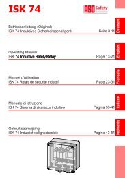
5. Verwendungsbeispiele<br />
5.1 .1 <strong>ISK</strong> <strong>77</strong> mit passiver Übertragung der mitfahrenden Schaltleisten<br />
SKL Open<br />
SKL Close<br />
<strong>SPK</strong> 55<br />
(feststehend)<br />
<strong>ISK</strong> <strong>77</strong><br />
Sicherheitsschaltgerät<br />
<strong>ISK</strong> Seilschleife<br />
<strong>SPK</strong> 54<br />
(mitfahrend)<br />
SKL<br />
Open<br />
SKL<br />
Close<br />
Steuerung (PLC)<br />
(kundenspezifisch)<br />
5.2 .2 <strong>SPK</strong> <strong>77</strong> mit feststehendem Spulenkern integriert<br />
SKL Open<br />
SKL Close<br />
<strong>SPK</strong> <strong>77</strong><br />
(feststehend)<br />
Steuerung (PLC)<br />
(kundenspezifisch)<br />
<strong>ISK</strong> Seilschleife<br />
<strong>SPK</strong> 54<br />
(mitfahrend)<br />
SKL<br />
Open<br />
SKL<br />
Close
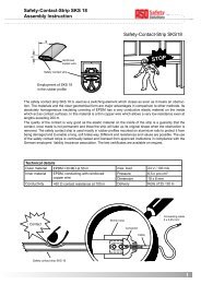
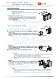
6. Geräteübersicht<br />
6.1 .1 Ausführungen<br />
6.1.1 .1.1 Gerätevariante <strong>ISK</strong> <strong>77</strong><br />
Der feststehende Spulenkern wird über ein Kabel an das Sicherheitsschaltgerät angeschlossen. Das<br />
Sicherheitsschaltgerät kann mit 4 Schrauben flach auf einen Untergrund geschraubt oder auf eine<br />
35mm Tragschiene aufgeschnappt werden. Im Fall der Tragschienenmontage besteht außerdem die<br />
Möglichkeit, die Anschraubfüsse abzutrennen.<br />
6.1.2 .1.2 Gerätevariante <strong>SPK</strong> <strong>77</strong><br />
Der feststehende Spulenkern ist im Sicherheitsschaltgerät integriert. Diese Gerätevariante wird über<br />
einen Halter direkt am Übertragungsseil montiert.<br />
6.1.3 .1.3 Variante F<br />
Es werden feststehende Schaltleisten ausgewertet. Über die nachfolgenden Buchstaben wird die<br />
Anschlussart für die feststehenden Schaltleisten bestimmt:<br />
Sichtkappe für<br />
7-Segmentanzeige<br />
<strong>ISK</strong> <strong>77</strong> FS <strong>SPK</strong> <strong>77</strong> FS<br />
Anschluss über steckbare Schraubklemmen<br />
<strong>SPK</strong> <strong>77</strong> FM<br />
Anschluss über eingegossene M8 Buchse<br />
<strong>ISK</strong> <strong>77</strong> FKM <strong>SPK</strong> <strong>77</strong> FKM<br />
Anschluss über eingegossenes Kabel mit M8 Kupplung<br />
abnehmbare Schutzkappe<br />
für 7-Segmentanzeige<br />
Deutsch<br />
7
Deutsch<br />
8<br />
<strong>ISK</strong> <strong>77</strong> / <strong>SPK</strong> <strong>77</strong> Induktives Sicherheitsschaltgerät<br />
6.1.4 .1.4 Variante E<br />
Steuerausgang als High Side Switch und Low Side Switch<br />
High<br />
Side<br />
Switch<br />
+<br />
OUT_H<br />
•<br />
•<br />
•<br />
alternative oder parallele Verwendung der Ausgänge möglich.<br />
Keine galvanische Trennung.<br />
Kat. 3 (interne Testung)<br />
Low<br />
Side<br />
Switch<br />
_<br />
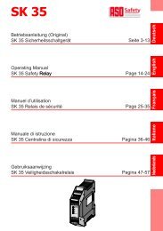
6.1.5 .1.5 Variante W<br />
Steuerausgang als Widerstandsausgang 8k2<br />
Widerstand<br />
8k2<br />
Im Ruhezustand beträgt der Widerstand zwischen den beiden Anschlüssen etwa 8,2 kW. Wird<br />
eine Betätigung der Schaltleisten gemeldet, so beträgt der Widerstand weniger als 100 W. Bei<br />
einer Störung oder Unterbrechung von Schaltleisten beträgt der Widerstand mehr als 100 kW.<br />
6.1.6 .1.6 Variante R<br />
Steuerausgang über Halbleiterrelais<br />
Halbleiter<br />
Relais<br />
Um eine extern angeforderte Testung entsprechend der Kategorie 2 durchführen zu können, wird<br />
diese Variante immer mit der Variante T (Testung) kombiniert.<br />
6.1.7 .1.7 Variante T<br />
Über drei Anschlussleitungen kann eine extern angeforderte Testung ausgeführt werden. Je nach<br />
Belegung der Anschlussleitung mit einer Spannung wird die Polarität und die Anforderung der<br />
Testung eingestellt.<br />
6.1.8 .1.8 Variante D<br />
OUT_L<br />
R 11<br />
R 12<br />
13<br />
14<br />
• Versorgung DC<br />
• Galvanische Trennung.<br />
• Kat. 3 (interne Testung)<br />
• Galvanische Trennung.<br />
• Nur Kat. 2 möglich<br />
• Versorgung AC / DC<br />
Das Sicherheitsschaltgerät besitzt eine Anzeige<br />
• Eventuell Anpassung an Steuerung notwendig.<br />
• Versorgung AC / DC
6.2 .2 Signalanzeigen<br />
SKL<br />
stationar��<br />
open<br />
SKL<br />
stationar��<br />
close<br />
TEST<br />
Bei Ausgabe einer Fehlermeldung gibt die Anzahl der ausgegebenen Pulse den Fehler an:<br />
6.3 .3 Anschlussklemmen<br />
Uin, Gnd:<br />
Spannungsversorgung DC für die Gerätevariante <strong>ISK</strong> <strong>77</strong> E. Die Plusleitung wird an Uin, und die<br />
Minusleitung wird an Gnd angeschlossen.<br />
B1, B2:<br />
Spannungsversorgung AC oder DC für die Gerätevarianten <strong>ISK</strong> <strong>77</strong> R oder <strong>ISK</strong> W. Die Polarität der<br />
Anschlussspannung ist unkritisch.<br />
SKL<br />
transmit<br />
open<br />
SKL<br />
transmit<br />
close<br />
FUN<br />
SKL Stationar�� open<br />
betätigt (an) - unterbrochen (blinkt)<br />
SKL Stationar�� close<br />
betätigt (an) - unterbrochen (blinkt)<br />
SKL Transmit open<br />
betätigt / unterbrochen (an)<br />
SKL Transmit close<br />
betätigt / unterbrochen (an)<br />
FUN<br />
Funktionskontrolle (kurz aus)<br />
Fehlermeldung (Pulsausgabe)<br />
TEST<br />
Testung aktiv (an)<br />
Pulse Fehlermeldung<br />
1 Spannungsversorgung außerhalb des gültigen Wertbereiches<br />
2 Ausgangssteuerung Open gestört<br />
3 Ausgangssteuerung Close gestört<br />
4 Datenübertragung zwischen Mikrocontroller gestört<br />
5 Übertragungsfehler <strong>ISK</strong><br />
9 1<br />
<strong>ISK</strong> SKL SKL<br />
open close<br />
Steckbare Schraubklemmen oder Kabelanschluss<br />
<strong>ISK</strong> <strong>77</strong> E:<br />
1: TST_MOD<br />
2: TST_COM<br />
3: TST_SIG<br />
4: CLOSE_OUT_L<br />
5: OPEN_OUT_L<br />
6: CLOSE_OUT_H<br />
7: OPEN_OUT_H<br />
8: Uin<br />
9: GND<br />
<strong>ISK</strong> <strong>77</strong> R / <strong>ISK</strong> <strong>77</strong> W:<br />
1: TST_MOD<br />
2: TST_COM<br />
3: TST_SIG<br />
4: CLOSE_OUT1<br />
5: CLOSE_OUT2<br />
6: OPEN_OUT2<br />
7: OPEN_OUT1<br />
8: B1<br />
9: B2<br />
Litzenfarben:<br />
1 = rosa<br />
2 = blau<br />
3 = grau<br />
4 = grün<br />
5 = gelb<br />
6 = braun<br />
7 = weiss<br />
8 = rot<br />
9 = schwarz<br />
Deutsch<br />
9
Deutsch<br />
10<br />
<strong>ISK</strong> <strong>77</strong> / <strong>SPK</strong> <strong>77</strong> Induktives Sicherheitsschaltgerät<br />
SKL open:<br />
Feststehende Schaltleisten für Laufrichtung Auf.<br />
SKL close:<br />
Feststehende Schaltleisten für Laufrichtung Zu.<br />
<strong>ISK</strong>:<br />
Dieser Anschluss ist bei den Gerätevarianten <strong>SPK</strong> <strong>77</strong> nicht verfügbar. Bei den Gerätevarianten<br />
<strong>ISK</strong> <strong>77</strong> wird hier der feststehende Spulenkern <strong>SPK</strong> 55 angeschlossen.<br />
OPEN_OUT_H, CLOSE_OUT_H:<br />
Steuerausgang als High Side Switch für den Steuerkreis Auf Richtung (OPEN_OUT_H) und für den<br />
Steuerkreis Zu Richtung (CLOSE_OUT_H). Wird an den Schaltleisten der Ruhezustand erkannt und<br />
liegt keine Störung im Gerät vor, so wird an den entsprechenden Steuerausgängen eine Spannung<br />
ausgegeben (entspricht der Anschlussspannung).<br />
OPEN_OUT_L, CLOSE_OUT_L:<br />
Steuerausgang als Low Side Switch für den Steuerkreis Auf Richtung (OPEN_OUT_L) und für den<br />
Steuerkreis Zu Richtung (CLOSE_OUT_L). Wird an den Schaltleisten der Ruhezustand erkannt und<br />
liegt keine Störung im Gerät vor, so wird der entsprechende Steuerausgang auf Gnd Potential gezogen.<br />
OPEN_OUT1, OPEN_OUT2:<br />
Steuerausgang für die Auf Richtung bei den Varianten <strong>ISK</strong> <strong>77</strong> R und <strong>ISK</strong> <strong>77</strong> W. Wird an den Schalt-<br />
leisten für die Auf Richtung der Ruhezustand erkannt und liegt keine Störung im Gerät vor, so wird<br />
der Einschaltzustand ausgegeben (<strong>ISK</strong> <strong>77</strong> R: Anschlüsse kurzgeschlossen, <strong>ISK</strong> <strong>77</strong> W: etwa 8,2 kOhm<br />
zwischen den Anschlüssen).<br />
CLOSE_OUT1, CLOSE_OUT2:<br />
Steuerausgang für die Zu Richtung bei den Varianten <strong>ISK</strong> <strong>77</strong> R und <strong>ISK</strong> <strong>77</strong> W. Wird an den Schaltleisten<br />
für die Zu Richtung der Ruhezustand erkannt und liegt keine Störung im Gerät vor, so wird der<br />
Einschaltzustand ausgegeben (<strong>ISK</strong> <strong>77</strong> R: Anschlüsse kurzgeschlossen, <strong>ISK</strong> <strong>77</strong> W: etwa 8,2 kOhm<br />
zwischen den Anschlüssen).<br />
TST_MOD, TST_SIG, TST_COM:<br />
Durch Anlegen einer separaten Spannung an den Anschluss TST_MOD gegen TST_COM wird der<br />
Modus für die Anforderung der Testung ausgewählt. Durch Anlegen einer separaten Spannung an<br />
den Anschluss TST_SIG gegen TST_COM steuert entsprechend des gewählten Modus die externe<br />
Testanforderung.<br />
7. Mechanische Befestigung<br />
Die mechanische Befestigung des Sicherheitsschaltgerätes ist fachgerecht an einem geeigneten<br />
Montageplatz auszuführen.<br />
Die beschriebenen Montageanleitungen gelten als Empfehlung. Die Anordnung der einzelnen<br />
Komponenten ist abhängig von der jeweiligen Torkonstruktion und von baulichen Gegebenheiten.<br />
Das Schaltgerät darf nicht in unmittelbarer Nähe von starken Wärmequellen montiert werden.<br />
Die Einbaulage des Schaltgerätes ist beliebig, sollte jedoch zum Schutz vor eindringender Feuchtig-<br />
keit so montiert werden, dass die Kabeleinführungen nach unten zeigen.<br />
Die Vorgehensweise für den Aufbau des <strong>ISK</strong> S��stems ist der separaten Montageanleitung zu<br />
entnehmen.
7.1 .1 <strong>ISK</strong> <strong>77</strong><br />
Das Gehäuse des <strong>ISK</strong> <strong>77</strong> erlaubt es, das Schaltgerät auf zwei verschiedene Arten zu befestigen.<br />
Es kann auf eine 35mm Tragschiene aufgeschnappt werden, die sich vorzugsweise in einem<br />
Schaltschrank befindet. Bei geringem Platzbedarf auf der Tragschiene können die Anschraubfüße<br />
abgetrennt werden.<br />
Über 4 Schrauben kann eine direkte Befestigung auf einem geeigneten Untergrund ausgeführt<br />
werden.<br />
7.2 .2 <strong>SPK</strong> <strong>77</strong><br />
Mit Hilfe des Befestigungsbügels wird das Schaltgerät mit dem integrierten feststehenden Spulenkern<br />
so montiert, dass das Seil bei der Torbewegung ohne Probleme durchlaufen kann.<br />
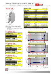
8. Anschließen der Signalgeber<br />
8.1 Anschluss am Spulenkern <strong>SPK</strong> 54<br />
Die mitfahrenden Leisten (SKL) werden mit dem<br />
mitfahrenden Spulenkern <strong>SPK</strong> 54 verbunden.<br />
Hierzu wird die mitfahrende SKL ZU Bewegung mit<br />
dem Anschluss C des mitfahrenden Spulenkerns<br />
verbunden und die optionale SKL AUF Bewegung<br />
mit dem Anschluss O.<br />
SKL<br />
AUF-Bewegung<br />
SKL<br />
ZU-Bewegung<br />
Sollte ein Kanal nicht genutzt werden, muss dieser mit einem 8,2 kW Widerstand<br />
belegt werden.<br />
8.2 Anschlussarten am Spulenkern <strong>SPK</strong> 54<br />
Über die nachfolgenden Buchstaben wird die Anschlussart am <strong>SPK</strong> 54 bestimmt:<br />
<strong>SPK</strong> 54 S<br />
Anschluss über<br />
steckbare Schraubklemme<br />
<strong>SPK</strong> 54 M<br />
Anschluss über<br />
eingegossene M8 Buchse<br />
C<br />
O<br />
<strong>SPK</strong> 54 KM<br />
Anschluss über<br />
eingegossenes Kabel mit M8 Kupplung<br />
Deutsch<br />
11
Deutsch<br />
12<br />
<strong>ISK</strong> <strong>77</strong> / <strong>SPK</strong> <strong>77</strong> Induktives Sicherheitsschaltgerät<br />
8.3 Anschluss von mehreren Signalgebern pro Signalgeberkreis (Bild 1)<br />
An dem Signalgebereingang O bzw. C können ein oder mehrere Signalgeber angeschlossen<br />
werden. Hierfür werden die einzelnen Signalgeber entsprechend Bild 1 in Serie geschaltet.<br />
Maximal können 5 Signalgeber mit einer Gesamtkabellänge von max. 25 m in Serie geschaltet werden.<br />
Die Länge eines Signalgebers kann bis zu 25m betragen.<br />
Vor dem Anschließen der in Serie geschalteten Signalgeber ist es empfehlenswert, den Widerstandswert<br />
der Verschaltung auszumessen.<br />
Bei unbetätigter SKL muss der Widerstand 8,2 kW ± 100 W betragen. Ist die SKL betätigt, darf der<br />
Widerstand 500 W nicht überschreiten.<br />
O<br />
2<br />
<strong>ASO</strong>-Signalgeber dürfen nicht parallel geschaltet werden.<br />
Signalgeber 1 Signalgeber 2 Signalgeber „n“<br />
C<br />
Bild 1: Verschaltung mehrerer Signalgeber, hier am Beispiel Sicherheitskontaktleiste<br />
9. Elektrische Inbetriebnahme<br />
Der Anschluss an die falschen Klemmen kann das Schaltgerät zerstören.<br />
9.1 .1 Voraussetzungen<br />
• Bei Versorgung mit 24 V AC/DC muss die Spannung den Anforderungen für Schutzkleinspannung<br />
SELV entsprechen.<br />
• Alle angelegten Spannungen müssen den Anforderungen für Schutzkleinspannung SELV<br />
entsprechen. Bei der Variante E sind die Ausgänge nicht von der Versorgungsspannung<br />
galvanisch getrennt.<br />
• Leitungen, die im Freien oder außerhalb vom Schaltschrank verlegt werden, müssen entsprechend<br />
geschützt werden.<br />
9.2 .2 Elektrischer Anschluss<br />
2<br />
• Versorgungsspannung 24 V an die Klemmen B1 B2 anschließen.<br />
• Feststehende Signalgeber an die Anschlüsse SKL OPEN und SKL CLOSE anschließen.<br />
• Den zu überwachenden Sicherheitsstromkreis an den entsprechenden Anschlüssen für Sicher-<br />
heitsausgänge Auf und Zu anschließen. Die Kabel sind so zu verlegen, dass eine Überbrückung<br />
der Sicherheitskontakte z. B. durch einen Kurzschluss zwischen den beiden Anschlussdrähten<br />
ausgeschlossen werden kann (insbesondere bei der Variante R).<br />
Nach erfolgreicher Inbetriebnahme sind die Sicherheitsausgänge aktiv. Eine Betätigung eines Signalgebers<br />
bewirkt ein Wechsel zum inaktiven Zustand des entsprechenden Sicherheitsausgangs.<br />
Auch während die Sicherheitsausgänge angesteuert sind, erfolgt eine fortlaufende Testung der<br />
Schaltfähigkeit (nicht bei der Variante R). Hierzu wird der Halbleiterausgang mehrfach pro Sekunde<br />
für weniger als 1 ms ausgeschaltet und das Verhalten am Ausgang überwacht. Wenn die Spannung<br />
am Ausgang nicht auf den Abschaltzustand wechselt, schaltet das Gerät dauerhaft ab und lässt sich<br />
nur durch Aus- und erneutes Einschalten der Spannungsversorgung zurücksetzen. Diese dauerhafte<br />
Abschaltung tritt auch dann auf, wenn die Spannung durch die Art der Anschaltung nicht zusammenbrechen<br />
kann (z.B. durch kapazitive Elemente).<br />
2<br />
2
9.3 .3 Testung mit Beschaltungsmöglichkeiten<br />
Für eine normenkonforme Auslegung der Schutzeinrichtung (Kategorie 2 mit externer Testanforderung)<br />
muss die übergeordnete Maschinensteuerung eine Testung vor jeder gefährlichen Fahrt<br />
oder in der ungefährlichen Phase / Bewegung der Maschine durchführen. Die Testung soll sicher-<br />
stellen, dass das Sicherheitsschaltgerät korrekt arbeitet. Nach Anlegen des Testsignals muss der Steuerausgang<br />
abschalten. Diese Schaltzustandsänderung muss durch die übergeordnete Maschinen-<br />
steuerung ausgewertet werden. Im korrekten Testfall leitet die Maschinensteuerung daraufhin die<br />
Fahrbewegung oder den nächsten Arbeitsschritt ein. Andernfalls muss die Steuerung eine Fehler-<br />
meldung ausgeben und eine gefahrbringende Bewegung verhindern. Wird ein Fehler in der Sicherheitseinrichtung<br />
durch die Maschinensteuerung erkannt, muss ein sicherer Zustand bis zur Behebung<br />
des Fehlers durch die Maschinensteuerung aufrechterhalten bleiben.<br />
Testsignal<br />
Ausgang (aktiv)<br />
(inaktiv)<br />
Durch Anlegen einer externen Spannung (Wertbereich 20 bis 35 Volt DC, 20 bis 28 Volt AC) wird<br />
entsprechend dem ausgewählten Modus eine extern angeforderte Testung ausgeführt.<br />
U test<br />
< 10 ms >25 ms<br />
< 50 ms<br />
sw sw<br />
TST-SIG TST-SIG<br />
TST-MOD<br />
Mit Betätigung des Schalters sw wird die Testung angefordert und führt zum Abschalten der Ausgänge.<br />
Der Betrieb oder die Beschaltung der Gerätevariante <strong>ISK</strong> <strong>77</strong> RT ohne Testung<br />
erfüllt keine bestimmte Sicherheitsanforderung.<br />
9.4 .4 Besonderheit der Sicherheitshalbleiterausgänge (OSSD)<br />
Die elektronischen Sicherheitshalbleiterausgänge des Schaltgerätes werden im laufenden Betrieb<br />
ständig getestet. Dazu wird der Ausgang z��klisch alle 0,4 Sekunden für eine Zeit von kleiner als 1 ms<br />
abgeschaltet und das Abschaltverhalten überprüft. Diese Unterbrechungen dürfen von der übergeordneten<br />
Steuerung nicht als Anforderung der Sicherheit gewertet werden.<br />
Eine übergeordnete Steuerung sollte die Zustände des Ausgangssignals nur bewerten, wenn der<br />
Pegel für 5ms ansteht. Damit wird vermieden, dass die Pulse vom Selbsttest im eingeschalteten<br />
Zustand und die Überprüfung des Einschaltvorgangs irrtümlich als Steuerinformation verarbeitet<br />
werden.<br />
U test<br />
TST-MOD<br />
TST-COM TST-COM<br />
Deutsch<br />
13
Deutsch<br />
14<br />
<strong>ISK</strong> <strong>77</strong> / <strong>SPK</strong> <strong>77</strong> Induktives Sicherheitsschaltgerät<br />
9.5 .5 Inbetriebnahme / Funktionsprüfung<br />
Nach entsprechendem Anschluss aller elektrischen Verbindungen und Einschalten der Versorgungs-<br />
spannung muss die Anlage / Maschine auf korrekte Funktion geprüft werden:<br />
• Betätigen Sie die Signalgeber der Reihe nach<br />
• Kontrollieren Sie die entsprechenden Reaktionen des Schaltgerätes<br />
Das Sicherheitss��stem muss in geeigneten Zeitabständen von Sachkundigen geprüft werden. Die<br />
Prüfung muss in jederzeit nachvollziehbarer Weise dokumentiert werden. Die Anforderungen des<br />
Anlagen- / Maschinenherstellers sind zu berücksichtigen und einzuhalten.<br />
10. Fehlerdiagnose<br />
Bei korrekter Verdrahtung und Anlegen der Versorgungsspannung darf auf der Anzeige nur der<br />
Dezimalpunkt z��klisch für kurze Zeit ausgeschaltet werden. Liegt ein interner Fehler vor, so wird<br />
über die Anzahl der Pulse die Fehlerkennung ausgegeben.<br />
LED Fehler Fehlerbeseitigung<br />
LED leuchten nicht Versorgungsspannung<br />
fehlt, zu gering oder falsch<br />
angeschlossen<br />
Dezimalpunkt blinkt<br />
z��klisch<br />
Mittlerer waagrechter<br />
Balken leuchtet<br />
Mindestens ein<br />
senkrechter Balken<br />
leuchtet dauerhaft<br />
Mindestens ein<br />
senkrechter Balken<br />
leuchtet blinkt<br />
Interner Fehler wird durch<br />
Anzahl Pulse angezeigt<br />
Anforderung Testung über<br />
externes Signal ist aktiv<br />
Die entsprechende Schaltleiste<br />
wird als betätigt<br />
erkannt.<br />
Die entsprechende Schaltleiste<br />
wird als unterbrochen<br />
erkannt<br />
Anschlüsse und Versorgungsspannung<br />
überprüfen<br />
Entsprechend der Fehlerkennzeichnung<br />
Ausgang abschalten, Gerät abschalten oder<br />
Versorgungsspannung prüfen.<br />
Beschaltung der Anschlüsse TST_MOD und<br />
TST_SIG überprüfen<br />
Anschlussleitung und Zustand der<br />
entsprechenden Schaltleisten prüfen<br />
Anschlussleitung und Zustand der<br />
entsprechenden Schaltleisten prüfen<br />
Liegt der Fehler nicht in der Verdrahtung, kann die Funktion der Elektronik durch Belegen des<br />
entsprechenden SKL Eingangs am Schaltgerät mit einem 8,2 kW Widerstand überprüft werden.<br />
11. Außerbetriebnahme und Entsorgung<br />
Die von <strong>ASO</strong> hergestellten Produkte sind ausschließlich für den gewerblichen Gebrauch (B2B)<br />
vorgesehen. Nach Nutzungsbeendigung sind die Produkte gemäß allen örtlichen, regionalen und<br />
nationalen Vorschriften zu entsorgen. <strong>ASO</strong> nimmt die Produkte auch gern zurück und entsorgt diese<br />
ordnungsgemäß.
12. Technische Daten<br />
Versorgungsspannung<br />
Kleinspannung: U E 24 V AC/DC ±10 % (nicht bei <strong>ISK</strong> <strong>77</strong> E / <strong>SPK</strong> <strong>77</strong> E)<br />
21,6 bis 35 V DC (nur bei <strong>ISK</strong> <strong>77</strong> E / <strong>SPK</strong> <strong>77</strong> E)<br />
Leistungsaufnahme P max 1 W (bei 24V DC ohne Verbraucher)<br />
Anschlusswiderstand Sicherheitskontaktleisten<br />
Nominalwert R nom = 8,2 kΩ<br />
oberer Schaltwert R AO > 12 kΩ<br />
unterer Schaltwert R AU < 5 kΩ<br />
Relaisausgänge (Halbleiterrelais)<br />
max. Schaltspannung 50 V<br />
max. Schaltstrom 50 mA<br />
Sicherheitshalbleiterausgänge<br />
Reaktionszeit < 10 ms (feststehende SKL)<br />
< 20 ms (<strong>ISK</strong>)<br />
Freischaltzeit 500 ms (25ms nach Testung)<br />
Testpuls < 10 ms<br />
Z��kluszeit Testpulse 0,4 Sekunden<br />
Gehäuse Vergussmasse PU schwarz<br />
Abmessungen (HxBxT)<br />
Feststehender Spulenkern <strong>SPK</strong> <strong>77</strong>: 100 x 39 x 30 mm<br />
Feststehender Spulenkern <strong>SPK</strong> 55: 40 x 39 x 30 mm<br />
Mitfahrender Spulenkern <strong>SPK</strong> 54: 38 x 45 x 33 mm<br />
Schaltgerät <strong>ISK</strong> <strong>77</strong>: 80 x 65 x 24 mm<br />
Schutzart IP65<br />
Gewicht<br />
Feststehender Spulenkern <strong>SPK</strong> <strong>77</strong>: 150 g<br />
Feststehender Spulenkern <strong>SPK</strong> 55: 100 g<br />
Mitfahrender Spulenkern <strong>SPK</strong> 54: 86 g<br />
Schaltgerät <strong>ISK</strong> <strong>77</strong>: 96 g<br />
Temperaturbereich -20° C bis +50° C<br />
Querschnitt Anschlussleitungen<br />
ein-, oder feindrähtige Leitung max. 0,5 mm 2<br />
Zulassungen<br />
<strong>ISK</strong> <strong>77</strong> FxETD, <strong>ISK</strong> <strong>77</strong> FxWTD<br />
DIN EN ISO 13849-1:2008 Kategorie 3 PL d<br />
(MTTFd = 620 Jahre , DCavg = 99,1%)<br />
<strong>ISK</strong> <strong>77</strong> FxRTD<br />
DIN EN ISO 13849-1:2008 Kategorie 2 PL d<br />
(MTTFd = 620 Jahre , DCavg = 94,53%)<br />
Sicherheitseinrichtung nach DIN EN 12978<br />
Alle an das Schaltgerät angeschlossenen Spannungen<br />
müssen sicher getrennte Spannungen sein!<br />
EG Baumuster Nr.:<br />
44 205 10 375347-001<br />
Zertifikat Nr.:<br />
44 780 10 375347-001<br />
Prüfbericht Nr.:<br />
10 205 375347<br />
Deutsch<br />
15
Deutsch<br />
16<br />
<strong>ISK</strong> <strong>77</strong> / <strong>SPK</strong> <strong>77</strong> Induktives Sicherheitsschaltgerät<br />
13. EG Konformitätserklärung<br />
Hiermit erklären wir, dass die nachfolgend bezeichneten Produkte der Baureihe:<br />
<strong>ISK</strong> <strong>77</strong> / <strong>SPK</strong> <strong>77</strong><br />
Induktive Übertragungsvorrichtung mit Sicherheitsschalts��stem zur Kombination<br />
mit Schaltleisten zur Vermeidung von Gefahren an Quetsch- und Scherstellen<br />
bei Tors��stemen<br />
<strong>ISK</strong> <strong>77</strong> mit <strong>SPK</strong> 55 und <strong>SPK</strong> 54<br />
<strong>SPK</strong> <strong>77</strong> mit <strong>SPK</strong> 54<br />
aufgrund ihrer Konzipierung und Bauart sowie in der von uns in Verkehr<br />
gebrachten Ausführung, den einschlägigen grundlegenden Sicherheits- und<br />
Gesundheitsanforderungen der nachfolgenden EG-Richtlinien und Normen<br />
entspricht:<br />
EG - Maschinenrichtlinie 2006/42/EG<br />
EN 12978:2003+A1:2009 / EN ISO 13849-1:2008 / EN ISO 13849-2:2008<br />
EN 61000-6-2:2005 / EN 61000-6-3:2007<br />
EG - Baumusterprüfung<br />
Notified Body 0044<br />
TÜV NORD CERT GmbH<br />
Langemarckstraße 20<br />
D-45141 Essen<br />
EG Baumuster Nr.: 44 205 10 375347-001<br />
Diese Konformitätserklärung entbindet den Konstrukteur/Hersteller der Maschine<br />
nicht von seiner Pflicht, die Konformität der gesamten Maschine, an der dieses<br />
Produkt angebracht wird, entsprechend der EG-Richtlinie sicherzustellen.<br />
Hersteller und Dokumentenbevollmächtigter:<br />
<strong>ASO</strong>, Antriebs- und Steuerungstechnik GmbH,<br />
Am Grarock 8, D-33154 Salzkotten<br />
Salzkotten, den XX.XX.2010<br />
Helmut Friedrich<br />
(Geschäftsführer und Dokumentenbevollmächtigter)
Produkte der Baureihe<br />
<strong>ISK</strong> <strong>77</strong> FKM (Artikelnummer xxxxxx, Format Seriennummer ����mmnnnnn)<br />
<strong>ISK</strong> <strong>77</strong> FS (Artikelnummer xxxxxx, Format Seriennummer ����mmnnnnn)<br />
<strong>ISK</strong> <strong>77</strong> FSETD (Artikelnummer 1210-0210, Format Seriennummer ����mmnnnnn)<br />
<strong>ISK</strong> <strong>77</strong> FSRTD (Artikelnummer 1210-0220, Format Seriennummer ����mmnnnnn)<br />
<strong>ISK</strong> <strong>77</strong> FSWTD (Artikelnummer 1210-0230, Format Seriennummer ����mmnnnnn)<br />
<strong>SPK</strong> <strong>77</strong> FKM (Artikelnummer xxxxxx, Format Seriennummer ����mmnnnnn)<br />
<strong>SPK</strong> <strong>77</strong> FM (Artikelnummer xxxxxx, Format Seriennummer ����mmnnnnn)<br />
<strong>SPK</strong> <strong>77</strong> FS (Artikelnummer xxxxxx, Format Seriennummer ����mmnnnnn)<br />
<strong>SPK</strong> <strong>77</strong> FSETD (Artikelnummer 1320-0250, Format Seriennummer ����mmnnnnn)<br />
<strong>SPK</strong> <strong>77</strong> FSRTD (Artikelnummer 1320-0260, Format Seriennummer ����mmnnnnn)<br />
<strong>SPK</strong> <strong>77</strong> FSWTD (Artikelnummer 1320-0270, Format Seriennummer ����mmnnnnn)<br />
<strong>SPK</strong> 55 (Artikelnummer 1319-0010, Format Seriennummer ����mmnnnnn)<br />
<strong>SPK</strong> 54 KM (Artikelnummer 1317-0030, Format Seriennummer ����mmnnnnn)<br />
<strong>SPK</strong> 54 M (Artikelnummer 1317-0020, Format Seriennummer ����mmnnnnn)<br />
<strong>SPK</strong> 54 S (Artikelnummer 1317-0010, Format Seriennummer ����mmnnnnn)<br />
Deutsch<br />
17
Deutsch<br />
18<br />
<strong>ISK</strong> <strong>77</strong> / <strong>SPK</strong> <strong>77</strong> Induktives Sicherheitsschaltgerät<br />
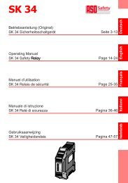
14. Montagemöglichkeiten<br />
14.1 .1 Wandmontage<br />
Die <strong>ISK</strong> <strong>77</strong> kann mit geeigneten Schrauben<br />
direkt auf den Befestigungsträger geschraubt<br />
werden (Abb.1).<br />
Abb.1<br />
14.2 .2 Tragschienenmontage<br />
Alternativ kann die <strong>ISK</strong> <strong>77</strong> auf einer 35mm Tragschiene montiert werden (Abb.2).<br />
Bei geringem Montageplatz können vorher die Anschraubfüsse mit einem Seitenschneider abgetrennt<br />
werden (Abb.3 + 4).<br />
Abb.2 Abb.3 Abb.4
<strong>ISK</strong> <strong>77</strong> / <strong>SPK</strong> <strong>77</strong><br />
Inductive <strong>Safety</strong> Relay<br />
1. Contents<br />
1. Contents. . . . . . . . . . . . . . . . . . . . . . . . . . . . . . . 19<br />
2. General safet�� regulations and protective measures . . . . . . . . 20<br />
3. General information and functional description . . . . . . . . . . . 21<br />
4. Proper use. . . . . . . . . . . . . . . . . . . . . . . . . . . . . . 21<br />
5. Application examples . . . . . . . . . . . . . . . . . . . . . . . . 22<br />
5.1 <strong>ISK</strong> <strong>77</strong> with passive transmission of the travelling safet�� edges . . . . . . . . . 22<br />
5.2 <strong>SPK</strong> <strong>77</strong> with integrated, stationar�� coil core . . . . . . . . . . . . . . . . . . . 22<br />
6. Device overview . . . . . . . . . . . . . . . . . . . . . . . . . . . 23<br />
6.1 Versions 7<br />
6.1.1 Device variant <strong>ISK</strong> <strong>77</strong> . . . . . . . . . . . . . . . . . . . . . . . . . . . 23<br />
6.1.2 Device variant <strong>SPK</strong> <strong>77</strong> . . . . . . . . . . . . . . . . . . . . . . . . . . . 23<br />
6.1.3 Variant F . . . . . . . . . . . . . . . . . . . . . . . . . . . . . . . . . . 23<br />
6.1.4 Variant E . . . . . . . . . . . . . . . . . . . . . . . . . . . . . . . . . . 24<br />
6.1.5 Variant W . . . . . . . . . . . . . . . . . . . . . . . . . . . . . . . . . . 24<br />
6.1.6 Variant R . . . . . . . . . . . . . . . . . . . . . . . . . . . . . . . . . . 24<br />
6.1.7 Variant T . . . . . . . . . . . . . . . . . . . . . . . . . . . . . . . . . . 24<br />
6.1.8 Variant D . . . . . . . . . . . . . . . . . . . . . . . . . . . . . . . . . . 24<br />
6.2 Signal indicators . . . . . . . . . . . . . . . . . . . . . . . . . . . . . . . . . 25<br />
6.3 Connection terminals . . . . . . . . . . . . . . . . . . . . . . . . . . . . . 25-26<br />
7. Mechanical mounting . . . . . . . . . . . . . . . . . . . . . . . . 26<br />
7.1 <strong>ISK</strong> <strong>77</strong> . . . . . . . . . . . . . . . . . . . . . . . . . . . . . . . . . . . . . . 27<br />
7.2 <strong>SPK</strong> <strong>77</strong> . . . . . . . . . . . . . . . . . . . . . . . . . . . . . . . . . . . . . . 27<br />
8. Connecting the sensors . . . . . . . . . . . . . . . . . . . . . . . 27<br />
8.1 Connecting to the <strong>SPK</strong> 54 coil core . . . . . . . . . . . . . . . . . . . . . . . 27<br />
8.2 Connection Connection t��pes t��pes t��pes on on the the <strong>SPK</strong> <strong>SPK</strong> 54 54 coil coil core core . . . . . . . . . . . . . . . . . . . . 27<br />
8.3 Connection of multiple sensors. . . . . . . . . . . . . . . . . . . . . . . . . . 28<br />
9. Electrical commissioning . . . . . . . . . . . . . . . . . . . . . . 28<br />
9.1 Prerequisites . . . . . . . . . . . . . . . . . . . . . . . . . . . . . . . . . . . 28<br />
9.2 Electrical connection . . . . . . . . . . . . . . . . . . . . . . . . . . . . . . . 28<br />
9.3 Testing with connection options . . . . . . . . . . . . . . . . . . . . . . . . . . 29<br />
9.4 Special features of the safet��-related safet��-related safet��-related semiconductor outputs (OSSD) . . . . . 29<br />
9.5 Commissioning / Functional test . . . . . . . . . . . . . . . . . . . . . . . . . 30<br />
10. Error diagnosis . . . . . . . . . . . . . . . . . . . . . . . . . . . 30<br />
11. Taking out of service and disposal . . . . . . . . . . . . . . . . . 30<br />
12. Technical specifications . . . . . . . . . . . . . . . . . . . . . . . 31<br />
13. EC declaration of conformit�� . . . . . . . . . . . . . . . . . . 32-33<br />
14. Mounting options . . . . . . . . . . . . . . . . . . . . . . . . . . 34<br />
14.1 Wall mounting . . . . . . . . . . . . . . . . . . . . . . . . . . . . . . . . . . 34<br />
14.1 Mounting-rail mounting. . . . . . . . . . . . . . . . . . . . . . . . . . . . . . 34<br />
English<br />
19
English<br />
20<br />
<strong>ISK</strong> <strong>77</strong> / <strong>SPK</strong> <strong>77</strong> Inductive <strong>Safety</strong> Relay<br />
2. General safety regulations and protective measures<br />
• The manufacturer and users of the plant / machine on which the protection is being used are<br />
responsible for implementing and following all applicable safet�� regulations and rules.<br />
• When used in conjunction with the higher-order controller, the protection guarantees functional<br />
safet��, but not the safet�� of the entire plant / machine. The safet�� of the entire plant / machine<br />
must, therefore, be assessed in accordance with machiner�� directive 2006/42/EC or appropriate<br />
product norm before using the device.<br />
• The operating instructions must alwa��s be available at the place of installation of the protection.<br />
The�� must be read thoroughl�� and observed b�� all persons involved in the operation, maintenance<br />
and servicing of the protection.<br />
• The protection must onl�� be installed and commissioned b�� professionals familiar with these<br />
operating instructions and the applicable operational safet�� and accident prevention regulations.<br />
All of the instructions provided in these operating instructions must be observed and followed.<br />
• All electrical work must onl�� be performed b�� skilled electricians. All relevant electrical engineering<br />
and Emplo��er's Liabilit�� Insurance Association safet�� regulations must be observed.<br />
• During work on the switching unit, it is to be switched to zero potential, checked to ensure that<br />
it is at zero potential and protected against being restarted.<br />
• If the potential-free contact of the rela�� output is supplied externall�� with a dangerous voltage,<br />
make certain that this voltage is switched off during work on the switching unit.<br />
• The switching unit does not contain an�� components that require servicing b�� the user.<br />
Unauthorised conversions and repairs made to the switching unit will void all guarantees and<br />
the manufacturer’s liabilit��.<br />
• The protection s��stem is to be professionall�� inspected at appropriate intervals and be documented<br />
in such a wa�� that it is comprehensible at all times.<br />
<strong>Safety</strong> advice<br />
• The switching unit enables operation at 24 V. Connecting the operating voltage to the wrong<br />
terminals can destro�� the switching unit.<br />
• For capacitive and inductive loads, ensure adequate protective circuits.<br />
The switching unit complies with EN ISO 13849 "<strong>Safety</strong>-related parts of control<br />
systems", category 3. To meet category 3 requirements, the switching unit is designed<br />
redundantly with two switching outputs per channel that monitor one another. Device<br />
variant R (semiconductor relay output) is designed in accordance with category 2<br />
with test input.<br />
The requirements of EN 12978 "<strong>Safety</strong> devices for power operated doors and gates" and<br />
EN 12453 "<strong>Safety</strong> in use of power operated gates" are also fulfilled.<br />
For the design of the safety system to conform to engineer standards, the plant / machine<br />
must be professionally inspected at appropriate intervals for proper function. The inspection<br />
must be documented in such a way as to be comprehensible at all times.<br />
For the design of the safety system to conform to engineer standards acc. to EN 13849<br />
category 2 for device variant R, the safety system must be tested prior to each dangerous<br />
movement of the plant / machine. Without testing, the operation or wiring of the safety relay<br />
does not satisfy these safety requirements.<br />
The manufacturer assumes no liability in the event of non-observance or intentional abuse.
3. General information and functional description<br />
The <strong>ISK</strong> signal transmission s��stem solves the problem of connecting moveable sensors to a<br />
stationar�� evaluation s��stem without mechanical stress. Communication between the moveable<br />
sensors and the electronic evaluation s��stem is based on induction. To achieve this, the monitoring<br />
electronics induce a frequenc�� on a coil core, which is integrated in a closed conductor loop.<br />
The second coil core, to which the moveable sensors are connected, receives this frequenc�� and<br />
sends corresponding feedback to the electronic evaluation s��stem in the event of cable break or<br />
actuation of a sensor.<br />
The <strong>ISK</strong> <strong>77</strong> / <strong>SPK</strong> <strong>77</strong> switching unit is used for evaluating safet�� contact edges for safeguarding<br />
locations where there is a risk of crushing and cutting.<br />
The switching unit is designed and t��pe-approved in accordance with EN ISO 13849 "Safet��-related<br />
parts of control s��stems" for Performance Level d. To meet the Performance Level, the switching<br />
unit has a redundant design with two independent semiconductor switches; the abilit�� of these<br />
switches to switch off is constantl�� tested.<br />
Monitoring of the standb�� current is made possible b�� an integrated terminating resistor in the<br />
sensors. If the specified standby current is flowing, a voltage is output at the respective outputs. If<br />
the sensor is actuated or the sensor circuit is interrupted, the voltage is switched off at the respective<br />
outputs.<br />
The monitoring state of the sensors and the applied operating voltage are indicated b�� LEDs.<br />
During troubleshooting after actuation / failure of the sensor or after a power failure, the switching<br />
unit automaticall�� re-enables the control circuits with a dela�� time.<br />
4. Proper use<br />
The switching unit is intended to be used as protection in combination with safet�� contact edges with<br />
integrated 8.2 KW resistor for standb��-current monitoring on a gate s��stem.<br />
An�� uses above and be��ond these uses constitute improper use. The manufacturer assumes no<br />
liabilit�� for damages arising from improper use.<br />
The <strong>ISK</strong> <strong>77</strong> / <strong>SPK</strong> <strong>77</strong> switching unit can only fulfil its safety-related task if used properly.<br />
The device ma�� onl�� be used in special applications with the manufacturer’s express consent.<br />
English<br />
21
English<br />
22<br />
<strong>ISK</strong> <strong>77</strong> / <strong>SPK</strong> <strong>77</strong> Inductive <strong>Safety</strong> Relay<br />
5. Application examples<br />
5.1 <strong>ISK</strong> <strong>77</strong> with passive transmission of the travelling safety edges<br />
SCE Open<br />
SCE Close<br />
<strong>SPK</strong> 55<br />
(stationar��)<br />
<strong>ISK</strong> <strong>77</strong><br />
Safet�� rela��<br />
<strong>ISK</strong> cable loop<br />
5.2 <strong>SPK</strong> <strong>77</strong> with integrated, stationary coil core<br />
SCE Open<br />
SCE Close<br />
<strong>SPK</strong> <strong>77</strong><br />
(stationar��)<br />
Controller (PLC)<br />
(customer specific)<br />
<strong>ISK</strong> cable loop<br />
<strong>SPK</strong> 54<br />
(travelling)<br />
SCE<br />
Open<br />
SCE<br />
Close<br />
Controller (PLC)<br />
(customer specific)<br />
<strong>SPK</strong> 54<br />
(travelling)<br />
SCE<br />
Open<br />
SCE<br />
Close
6. Device overview<br />
6.1 Versions<br />
6.1.1 Device variant <strong>ISK</strong> <strong>77</strong><br />
The stationar�� coil core is connected to the safet�� rela�� via a cable. The safet�� rela�� can be screwed<br />
flat to a base with 4 screws or snapped onto a 35 mm mounting rail. In the case of rail mounting, it<br />
is also possible to cut off the bolt-on feet.<br />
6.1.2 Device variant <strong>SPK</strong> <strong>77</strong><br />
The stationar�� coil core is integrated in the safet�� rela��. This device variant is installed directl�� on<br />
the transmission cable via a bracket.<br />
6.1.3 Variant F<br />
Stationar�� safet�� edges are evaluated. The connection t��pe for the stationar�� safet�� edges is determined<br />
using the following letters:<br />
Sight cap for 7-segment<br />
displa��<br />
<strong>ISK</strong> <strong>77</strong> FS <strong>SPK</strong> <strong>77</strong> FS<br />
Connection via plug-in screw terminals<br />
<strong>SPK</strong> <strong>77</strong> FM<br />
Connection via moulded M8 female connector<br />
<strong>ISK</strong> <strong>77</strong> FKM <strong>SPK</strong> <strong>77</strong> FKM<br />
Connection via moulded cable with M8 female connector<br />
Removable protective cap<br />
for 7-segment displa��<br />
English<br />
23
English<br />
24<br />
<strong>ISK</strong> <strong>77</strong> / <strong>SPK</strong> <strong>77</strong> Inductive <strong>Safety</strong> Relay<br />
6.1.4 Variant E<br />
Control output as high-side switch and low-side switch<br />
High<br />
Side<br />
Switch<br />
+<br />
OUT_H<br />
•<br />
•<br />
•<br />
Alternative or parallel use of the outputs possible<br />
No galvanic separation<br />
Cat. 3 (internal testing)<br />
Low<br />
Side<br />
Switch<br />
_<br />
6.1.5 Variant W<br />
Control output as 8k2 resistance output<br />
resistor<br />
8k2<br />
While in the idle state, the resistance between the two connections is approximatel�� 8.2k kW. If actuation<br />
of the safet�� edges is reported, the resistance is less than 100 W. In the event of a fault or interruption<br />
of safet�� edges, the resistance is greater than 100 kW.<br />
6.1.6 Variant R<br />
Control output via semiconductor rela��<br />
Semiconductor<br />
rela��<br />
In order to perform an externall�� requested test in accordance with categor�� 2, this variant is alwa��s<br />
combined with variant T (test).<br />
6.1.7 Variant T<br />
An externall�� requested test can be performed via three connection cables. The polarit�� and test<br />
request are set according to the configuration of the connection cable with voltage.<br />
6.1.8 Variant D<br />
OUT_L<br />
R 11<br />
R 12<br />
13<br />
14<br />
• DC suppl��<br />
The safet�� rela�� is equipped with a displa��.<br />
• Galvanic separation<br />
• Cat. 3 (internal testing)<br />
• Adaptation to the controller ma�� be necessar��.<br />
• AC / DC suppl��<br />
• Galvanic separation<br />
• Onl�� Cat. 2 possible<br />
• AC / DC suppl��
6.2 Signal indicators<br />
During the output of an error message, the number of output pulses indicates the error:<br />
6.3 Connection terminals<br />
Uin, Gnd:<br />
DC voltage suppl�� for device variant <strong>ISK</strong> <strong>77</strong> E. A positive cable is connected to Uin, and the negative<br />
cable is connected to Gnd.<br />
B1, B2:<br />
SCE<br />
stationar��<br />
open<br />
SCE<br />
stationar��<br />
close<br />
TEST<br />
SCE<br />
transmit<br />
open<br />
SCE<br />
transmit<br />
close<br />
FUN<br />
Pulse Error message<br />
1 Voltage suppl�� outside of the valid value range<br />
2 Output control Open fault��<br />
3 Output control Close fault��<br />
4 Data transmission with microcontroller fault��<br />
5 <strong>ISK</strong> transmission error<br />
9 1<br />
<strong>ISK</strong> SCE SCE<br />
open close<br />
SCE Stationar�� open<br />
actuated (on) - interrupted (flashes)<br />
SCE Stationar�� close<br />
actuated (on) - interrupted (flashes)<br />
SCE Transmit open<br />
actuated / interrupted (on)<br />
SCE Transmit close<br />
actuated / interrupted (on)<br />
FUN<br />
Functional test (off briefly)<br />
Error message (pulse output)<br />
TEST<br />
Test active (on)<br />
Plug-in screw terminals or cable connection<br />
<strong>ISK</strong> <strong>77</strong> E:<br />
1: TST_MOD<br />
2: TST_COM<br />
3: TST_SIG<br />
4: CLOSE_OUT_L<br />
5: OPEN_OUT_L<br />
6: CLOSE_OUT_H<br />
7: OPEN_OUT_H<br />
8: Uin<br />
9: GND<br />
<strong>ISK</strong> <strong>77</strong> R / <strong>ISK</strong> <strong>77</strong> W:<br />
1: TST_MOD<br />
2: TST_COM<br />
3: TST_SIG<br />
4: CLOSE_OUT1<br />
5: CLOSE_OUT2<br />
6: OPEN_OUT2<br />
7: OPEN_OUT1<br />
8: B1<br />
9: B2<br />
Colors of wires:<br />
1 = pink<br />
2 = blue<br />
3 = gra��<br />
4 = green<br />
5 = ��ellow<br />
6 = brown<br />
7 = white<br />
8 = red<br />
9 = black<br />
AC or DC voltage suppl�� for device variant <strong>ISK</strong> <strong>77</strong> R or <strong>ISK</strong> W. The polarit�� of the suppl�� voltage is<br />
not critical.<br />
English<br />
25
English<br />
26<br />
<strong>ISK</strong> <strong>77</strong> / <strong>SPK</strong> <strong>77</strong> Inductive <strong>Safety</strong> Relay<br />
SCE open:<br />
Stationar�� safet�� edges for Opening direction of movement.<br />
SCE close:<br />
Stationar�� safet�� edges for Closing direction of movement.<br />
<strong>ISK</strong>:<br />
This connection is not available for the <strong>SPK</strong> <strong>77</strong> device variants. With the <strong>ISK</strong> <strong>77</strong> device variants, the<br />
<strong>SPK</strong> 55 stationar�� coil core is connected here.<br />
OPEN_OUT_H, CLOSE_OUT_H:<br />
Control output as high side switch for the Opening direction control circuit (OPEN_OUT_H) and for<br />
the Closing direction control circuit (CLOSE_OUT_H). If the idle state is detected at the safet�� edges<br />
and if there are no faults present in the device, a voltage is output at the respective control outputs<br />
(corresponds to the suppl�� voltage).<br />
OPEN_OUT_L, CLOSE_OUT_L:<br />
Control output as low side switch for the Opening direction control circuit (OPEN_OUT_H) and for the<br />
Closing direction control circuit (CLOSE_OUT_L). If the idle state is detected at the safet�� edges and if<br />
there are no faults present in the device, the respective control output is pulled to Gnd potential.<br />
OPEN_OUT1, OPEN_OUT2:<br />
Control output for the Opening direction for the <strong>ISK</strong> <strong>77</strong> R and <strong>ISK</strong> <strong>77</strong> W variants. variants. If If the idle state is<br />
detected at the safet�� edges for the Opening direction and if there are no faults present in the device,<br />
the switch-on state is output (<strong>ISK</strong> <strong>77</strong> R: connections short-circuited, <strong>ISK</strong> <strong>77</strong> W: approx. 8.2 kΩ between<br />
the connections).<br />
CLOSE_OUT1, CLOSE_OUT2:<br />
Control output for the Closing direction for the <strong>ISK</strong> <strong>77</strong> R and <strong>ISK</strong> <strong>77</strong> W variants. If the idle state is<br />
detected at the safet�� edges for the Closing direction and if there are no faults in the device, the<br />
switch-on state is output (<strong>ISK</strong> <strong>77</strong> R: connections short-circuited, <strong>ISK</strong> <strong>77</strong> W: approx. 8.2 kΩ between<br />
the connections).<br />
TST_MOD, TST_SIG, TST_COM:<br />
B�� appl��ing a separate voltage to the TST_MOD connection against TST_COM, the mode for<br />
requesting the test is selected. Appl��ing a separate voltage to the TST_SIG connection against<br />
TST_COM controls the external test request according to the selected mode.<br />
7. Mechanical mounting<br />
Mechanical mounting of the safet�� rela�� is to be performed professionall�� at a suitable mounting<br />
location.<br />
The provided assembl�� instruction are recommendations onl��. The actual arrangement of the<br />
individual components depends on the design of the gate in question and the conditions at the<br />
installation site.<br />
The switching unit must not be mounted in the immediate vicinit�� of strong sources of heat.<br />
The switching unit ma�� be mounted in an�� orientation. To prevent moisture penetration, it should,<br />
however, be installed so that the cable conduits point downward.<br />
The procedure for constructing the <strong>ISK</strong> s��stem can be found in the separate assembl�� instructions.
7.1 <strong>ISK</strong> <strong>77</strong><br />
The housing of the <strong>ISK</strong> <strong>77</strong> allows the switching unit to be mounted in two different wa��s. It can be<br />
snapped onto a 35 mm mounting rail, preferabl�� located in a switching cabinet. If there is limited<br />
space available on the mounting rail, the bolt-on feet can be cut off.<br />
The housing can be directl�� mounted to a suitable base using four screws.<br />
7.2 <strong>SPK</strong> <strong>77</strong><br />
With the aid of the mounting bracket, the switching unit with the integrated stationar�� coil core is<br />
mounted so that the cable can move through without problem during the gate movement.<br />
8. Connecting the sensors<br />
8.1 Connecting to the <strong>SPK</strong> 54 coil core<br />
The travelling edges (SCE) are connected to the<br />
<strong>SPK</strong> 54 travelling coil core.<br />
For this purpose, the travelling SCE CLOSING<br />
movement is connected to connection C of the<br />
travelling coil core and the optional SCE OPENING<br />
movement is connected to connection O.<br />
If a channel is not used, it must be connected to an 8.2 k kW resistor.<br />
8.2 Connection types on the <strong>SPK</strong> 54 coil core<br />
The connection t��pe on the <strong>SPK</strong> 54 is determined with the following letters:<br />
<strong>SPK</strong> 54 S<br />
Connection via plug-in<br />
screw terminal<br />
<strong>SPK</strong> 54 M<br />
Connection via moulded<br />
M8 female connector<br />
C<br />
O<br />
SCE<br />
OPENING<br />
movement<br />
SCE<br />
CLOSING<br />
movement<br />
<strong>SPK</strong> 54 KM<br />
Connection via moulded cable<br />
with M8 female connector<br />
English<br />
27
English<br />
28<br />
<strong>ISK</strong> <strong>77</strong> / <strong>SPK</strong> <strong>77</strong> Inductive <strong>Safety</strong> Relay<br />
8.3 Connecting multiple sensors per sensor circuit (figure 1)<br />
One or more sensors can be connected to sensor input O or C. For this purpose, the individual<br />
sensors are connected in series according to figure 1.<br />
Up to five sensors may be connected in series, whereby the total cable length must not exceed 25 m.<br />
The length of one sensor ma�� be up to 25 m.<br />
Before connecting the sensors that are connected in series, it is recommended that the resistance<br />
value of the arrangement be measured.<br />
The resistance must be 8.2 kW ± 100 W when the SCE is inactive and must not exceed 500 W when<br />
it is active.<br />
O<br />
2<br />
<strong>ASO</strong> sensors must not be connected in parallel.<br />
Sensor 1<br />
9. Electrical commissioning<br />
2<br />
Sensor 2<br />
C<br />
Figure 1: Wiring of multiple sensors; in this example: safety contact edge<br />
Sensor "n"<br />
Connecting to the wrong terminals can destroy the switching unit.<br />
9.1 Prerequisites<br />
• When suppl��ing with 24 V AC/DC, the voltage must compl�� with the requirements for Safet�� Low<br />
Voltage (SELV).<br />
• All applied voltages must compl�� with the requirements for Safet�� Low Voltage (SELV). With<br />
variant E, the outputs are not galvanicall�� separated from the suppl�� voltage.<br />
• Cables installed outdoors or outside of the switching cabinet must be protected appropriatel��.<br />
9.2 Electrical connection<br />
• Connect 24 V suppl�� voltage to terminals B1 B2.<br />
• Connect stationar�� sensors to the SCE OPEN and SCE CLOSE connections.<br />
• Connect the safet�� circuit to be monitored to the appropriate connections for safet�� outputs Open<br />
and Close. The cables are to be laid so that it is impossible to bridge the safet�� contacts, e.g. b��<br />
a short circuit between the two connection wires (particularl�� with variant R).<br />
Following successful commissioning, safet�� outputs are active. Actuation of a sensor causes the<br />
respective safet�� output to switch to the inactive state.<br />
Even while the safet�� outputs are being activated, their abilit�� to turn off is constantl�� tested (not with<br />
variant R). For this purpose, the semiconductor output is switched off several times per second for<br />
less than 1 ms and the response at the output monitored. If the voltage at the output does not switch<br />
to the shut-down state, the device deactivates permanentl�� and can onl�� be reset b�� switching the<br />
voltage suppl�� off and back on again. This permanent deactivation also occurs if, depending on the<br />
t��pe of activation, the voltage cannot break down (e.g. b�� means of capacitive elements).<br />
2<br />
2
9.3 Testing with connection options<br />
For the design of the protection to conform to engineer standards (categor�� 2 with external test<br />
request), the protection must be tested prior to each dangerous movement or during the non-<br />
dangerous phase/movement of the machine. The test is intended to ensure the proper function of<br />
the safet�� rela��. After appl��ing the test signal, the control output must deactivate. This change in<br />
switching state must be evaluated b�� the primar�� machine control. If the test result is correct, the machine<br />
control then initiates the movement or the next work step. Otherwise, the controller must output an<br />
error message and prevent a dangerous movement. If the machine control detects an error fault in<br />
the safety device, the machine control must maintain a safe state until the error is rectified.<br />
Test signal<br />
Output (active)<br />
(inactive)<br />
B�� appl��ing an external voltage (value range 20 to 35 volt DC, 20 to 28 volt AC), an externall�� requested<br />
test is performed according to the selected mode.<br />
U test<br />
< 10 ms >25 ms<br />
< 50 ms<br />
sw sw<br />
TST-SIG TST-SIG<br />
TST-MOD<br />
Upon actuation of switch sw, the test is requested and results in the deactivation of the outputs.<br />
Without testing, the operation or wiring of device variant <strong>ISK</strong> <strong>77</strong> RT satisfies no<br />
specific safety requirements.<br />
9.4 Special feature of the safety-related semiconductor outputs (OSSD)<br />
The electronic safet��-related semiconductor outputs of the switching unit are constantl�� tested during<br />
running operation. For this purpose, the output is c��clicall�� switched off ever�� 0.4 seconds for a period<br />
less than 1 ms and the shut-down behaviour tested. These interruptions must not be evaluated b��<br />
the higher-order controller as safet�� requests.<br />
A primar�� controller should onl�� evaluate the states of the output signal if the level is sustained for<br />
5 ms. This prevents pulses generated during a self-test while in the switched-on state and the testing<br />
of the switch-on procedure from erroneousl�� being processed as control information.<br />
U test<br />
TST-MOD<br />
TST-COM TST-COM<br />
English<br />
29
English<br />
30<br />
<strong>ISK</strong> <strong>77</strong> / <strong>SPK</strong> <strong>77</strong> Inductive <strong>Safety</strong> Relay<br />
9.5. Commissioning / functional test<br />
The plant / machine must be tested for proper function after all of the electrical connections have<br />
been established and the suppl�� voltage has been turned on.<br />
• Actuate the sensors in sequence.<br />
• Check the switching units for proper reaction.<br />
The safet�� s��stem must be professionall�� inspected at appropriate intervals. The inspection must<br />
be documented in such a wa�� as to be comprehensible at all times. The requirements of the plant/<br />
machine manufacturer are to be taken into account and followed.<br />
10. Error diagnosis<br />
If the suppl�� voltage is both wired and applied correctl��, the decimal point must switch off c��clicall��<br />
on the display only briefly. If an internal error has occurred, the error message is indicated by the<br />
number of pulses.<br />
LED Error Error correction<br />
LEDs are not illuminated<br />
Decimal point flashes<br />
c��clicall��<br />
Middle horizontal<br />
bar illuminates<br />
At least one vertical<br />
bar illuminates constantl��<br />
At least one vertical<br />
bar flashes<br />
The suppl�� voltage is missing,<br />
too low or has been<br />
connected incorrectl��<br />
Internal error is indicated<br />
b�� the number of pulses<br />
Test request via external<br />
signal is active<br />
The corresponding safet��<br />
edge detected as having<br />
been actuated<br />
The corresponding safet��<br />
edge detected as having<br />
been interrupted<br />
Check connections and suppl�� voltage<br />
According to the error indicator, switch off<br />
the output, switch off the device or check the<br />
suppl�� voltage<br />
Check wiring of the TST_MOD and<br />
TST_SIG connections<br />
Check connection cable and state of the<br />
corresponding safet�� edges<br />
Check connection cable and state of the<br />
corresponding safet�� edges<br />
If the error is not in the wiring, the function of the electronics can be tested b�� connecting an<br />
8.2 kW resistor to the respective SCE input on the switching unit.<br />
11. Taking out of service and disposal<br />
The products manufactured b�� <strong>ASO</strong> are intended solel�� for commercial use (B2B). At the end of use,<br />
the products are to be disposed of according to all local, regional and national regulations. Products<br />
can also be returned to <strong>ASO</strong>, which will then dispose of them properl��.
12. Technical specifications<br />
Supply voltage<br />
Low voltage: U E 24 V AC/DC ±10 % (not for <strong>ISK</strong> <strong>77</strong> E / <strong>SPK</strong> <strong>77</strong> E)<br />
21,6 bis 35 V DC (onl�� for <strong>ISK</strong> <strong>77</strong> E / <strong>SPK</strong> <strong>77</strong> E)<br />
Power consumption Pmax 1 W (with 24V DC without load)<br />
Terminal resistance of the SCEs<br />
nominal value Rnom upper switching point RAO lower switching point RAU = 8,2 kΩ<br />
> 12 kΩ<br />
< 5 kΩ<br />
Relay outputs (semiconductor relay)<br />
Max. switching voltage 50 V<br />
Max. switching current 50 mA<br />
<strong>Safety</strong> related semiconductor outputs<br />
Response time < 10 ms (stationar�� SCE)<br />
< 20 ms (<strong>ISK</strong>)<br />
Turn-off time 500 ms (25ms after test)<br />
Test pulse < 10 ms<br />
C��cle time of test pulse 0,4 seconds<br />
Housing Black PU potting compound<br />
Dimensions (HxWxD)<br />
Stationar�� coil core <strong>SPK</strong> <strong>77</strong>: 100 x 39 x 30 mm<br />
Stationar�� coil core <strong>SPK</strong> 55: 40 x 39 x 30 mm<br />
Travelling coil core <strong>SPK</strong> 54: 38 x 45 x 33 mm<br />
Switching unit <strong>ISK</strong> <strong>77</strong>: 80 x 65 x 24 mm<br />
Protection class IP65<br />
Weight<br />
Stationar�� coil core <strong>SPK</strong> <strong>77</strong>: 150 g<br />
Stationar�� coil core <strong>SPK</strong> 55: 100 g<br />
Travelling coil core <strong>SPK</strong> 54: 86 g<br />
Switching unit <strong>ISK</strong> <strong>77</strong>: 96 g<br />
Temperature range -20° C to +50° C<br />
Connection cable cross-section<br />
single- or fine-stranded cable max. 0,5 mm 2<br />
Certifications<br />
<strong>ISK</strong> <strong>77</strong> FxETD, <strong>ISK</strong> <strong>77</strong> FxWTD<br />
DIN EN ISO 13849-1:2008 categor�� 3 PL d<br />
(MTTFd = 620 ��ears, DCavg = 99.1%)<br />
<strong>ISK</strong> <strong>77</strong> FxRTD<br />
DIN EN ISO 13849-1:2008 categor�� 2 PL d<br />
(MTTFd = 620 ��ears, DCavg = 94.53%)<br />
Safet�� equipment in accordance with DIN EN 12978<br />
All voltages connected to the switching unit must be safely isolated!<br />
EC type examination no.:<br />
44 205 10 375347-001<br />
Certificate no.:<br />
44 780 10 375347-001<br />
Test report no.:<br />
10 205 375347<br />
English<br />
31
English<br />
32<br />
<strong>ISK</strong> <strong>77</strong> / <strong>SPK</strong> <strong>77</strong> Inductive <strong>Safety</strong> Relay<br />
13. EC declaration of conformity<br />
We hereb�� declare that the following products of t��pe series:<br />
<strong>ISK</strong> <strong>77</strong> / <strong>SPK</strong> <strong>77</strong><br />
Inductive transmission device with safet�� switching s��stem to be used in combination<br />
with safet�� edges for preventing dangers at locations on gate s��stems<br />
where there is a risk of crushing and cutting<br />
<strong>ISK</strong> <strong>77</strong> with <strong>SPK</strong> 55 and <strong>SPK</strong> 54<br />
<strong>SPK</strong> <strong>77</strong> with <strong>SPK</strong> 54<br />
satisfies the relevant essential health and safety requirements of the EC directives<br />
and standards listed below on account of its design and construction, as<br />
does the version brought to market b�� us:<br />
EC - machinery directive 2006/42/EC<br />
EN 12978:2003+A1:2009 / EN ISO 13849-1:2008 / EN ISO 13849-2:2008<br />
EN 61000-6-2:2005 / EN 61000-6-3:2007<br />
EC - type approval<br />
Notified Body 0044<br />
TÜV NORD CERT GmbH<br />
Langemarckstraße 20<br />
D-45141 Essen<br />
EC t��pe examination no.: 44 205 10 375347-001<br />
This declaration of conformit�� does not relieve the designer/manufacturer of the<br />
machine from his obligation to ensure that the conformit�� of the entire machine<br />
to which this product is attached satisfies the corresponding EC directive.<br />
Manufacturer and Authorised Signatory:<br />
<strong>ASO</strong>, Antriebs- und Steuerungstechnik GmbH,<br />
Am Grarock 8, D-33154 Salzkotten / German��<br />
Salzkotten, XX.XX.2010<br />
Helmut Friedrich<br />
(General Manager and Authorised Signator��)
Products of the series<br />
<strong>ISK</strong> <strong>77</strong> FKM (part no. xxxxxx, serial number format ����mmnnnnn)<br />
<strong>ISK</strong> <strong>77</strong> FS (part no. xxxxxx, serial number format ����mmnnnnn)<br />
<strong>ISK</strong> <strong>77</strong> FSETD (part no. 1210-0210, serial number format ����mmnnnnn)<br />
<strong>ISK</strong> <strong>77</strong> FSRTD part no. 1210-0220, serial number format ����mmnnnnn)<br />
<strong>ISK</strong> <strong>77</strong> FSWTD (part no. 1210-0230, serial number format ����mmnnnnn)<br />
<strong>SPK</strong> <strong>77</strong> FKM (part no. xxxxxx, serial number format ����mmnnnnn)<br />
<strong>SPK</strong> <strong>77</strong> FM (part no. xxxxxx, serial number format ����mmnnnnn)<br />
<strong>SPK</strong> <strong>77</strong> FS (part no. xxxxxx, serial number format ����mmnnnnn)<br />
<strong>SPK</strong> <strong>77</strong> FSETD (part no. 1320-0250, serial number format ����mmnnnnn)<br />
<strong>SPK</strong> <strong>77</strong> FSRTD (part no. 1320-0260, serial number format ����mmnnnnn)<br />
<strong>SPK</strong> <strong>77</strong> FSWTD (part no. 1320-0270, serial number format ����mmnnnnn)<br />
<strong>SPK</strong> 55 (part no. 1319-0010, serial number format ����mmnnnnn)<br />
<strong>SPK</strong> 54 KM (part no. 1317-0030, serial number format ����mmnnnnn)<br />
<strong>SPK</strong> 54 M (part no. 1317-0020, serial number format ����mmnnnnn)<br />
<strong>SPK</strong> 54 S (part no. 1317-0010, serial number format ����mmnnnnn)<br />
English<br />
33
English<br />
34<br />
<strong>ISK</strong> <strong>77</strong> / <strong>SPK</strong> <strong>77</strong> Inductive <strong>Safety</strong> Relay<br />
14. Mounting options<br />
14.1 .1 Wall mounting<br />
mounting<br />
The <strong>ISK</strong> <strong>77</strong> can be screwed directl�� onto the<br />
mounting bracket with appropriate screws (fig. 1).<br />
14.2 .2 Mounting-rail mounting<br />
Alternativel��, the <strong>ISK</strong> <strong>77</strong> can be mounted on a 35 mm mounting rail (fig. 2).<br />
If there is limited mounting space, the bolt-on feet can be cut-off with side-cutting pliers (figs. 3 and 4)<br />
fig.1 .1<br />
fig.2 .2 fig.3 .3 fig.4 .4
<strong>ISK</strong> <strong>77</strong> / <strong>SPK</strong> <strong>77</strong><br />
Relais de sécurité inductif<br />
1. Table des matières<br />
1. Table des matières . . . . . . . . . . . . . . . . . . . . . . . . . 35<br />
2. Prescriptions générales de sécurité et mesures de protection . . . 36<br />
3. Généralités et description du fonctionnement. . . . . . . . . . . . 37<br />
4. Utilisation conforme . . . . . . . . . . . . . . . . . . . . . . . . . 37<br />
5. Exemples d'utilisation . . . . . . . . . . . . . . . . . . . . . . . . 38<br />
5.1 <strong>ISK</strong> <strong>77</strong> avec transmission passive des barres palpeuses mobiles . . . . . . . . 38<br />
5.2 <strong>SPK</strong> <strong>77</strong> avec noyau de bobine fixe intégré . . . . . . . . . . . . . . . . . . . . 38<br />
6. Vue d'ensemble de l'appareil . . . . . . . . . . . . . . . . . . . . 39<br />
6.1 Modèles 7<br />
6.1.1 Variante <strong>ISK</strong> <strong>77</strong>. . . . . . . . . . . . . . . . . . . . . . . . . . . . . . . 39<br />
6.1.2 Variante <strong>SPK</strong> <strong>77</strong> . . . . . . . . . . . . . . . . . . . . . . . . . . . . . . 39<br />
6.1.3 Variante F. . . . . . . . . . . . . . . . . . . . . . . . . . . . . . . . . . 39<br />
6.1.4 Variante E . . . . . . . . . . . . . . . . . . . . . . . . . . . . . . . . . 40<br />
6.1.5 Variante W . . . . . . . . . . . . . . . . . . . . . . . . . . . . . . . . . 40<br />
6.1.6 Variante R . . . . . . . . . . . . . . . . . . . . . . . . . . . . . . . . . 40<br />
6.1.7 Variante T. . . . . . . . . . . . . . . . . . . . . . . . . . . . . . . . . . 40<br />
6.1.8 Variante D . . . . . . . . . . . . . . . . . . . . . . . . . . . . . . . . . 40<br />
6.2 Indicateurs . . . . . . . . . . . . . . . . . . . . . . . . . . . . . . . . . . . . 41<br />
6.3 Bornes de connexion . . . . . . . . . . . . . . . . . . . . . . . . . . . . . 41-42<br />
7. Fixation mécanique . . . . . . . . . . . . . . . . . . . . . . . . . 42<br />
7.1 <strong>ISK</strong> <strong>77</strong> . . . . . . . . . . . . . . . . . . . . . . . . . . . . . . . . . . . . . . 43<br />
7.2 <strong>SPK</strong> <strong>77</strong> . . . . . . . . . . . . . . . . . . . . . . . . . . . . . . . . . . . . . . 43<br />
8. Raccordement des émetteurs de signaux. . . . . . . . . . . . . . 43<br />
8.1 Raccordement au no��au de bobine <strong>SPK</strong> 54 . . . . . . . . . . . . . . . . . . . 43<br />
8.2 T��pes T��pes T��pes de de raccordement raccordement au no��au no��au no��au de bobine <strong>SPK</strong> <strong>SPK</strong> 54 54 . . . . . . . . . . . . . . 43<br />
8.3 Raccordement de plusieurs émetteurs de signaux. . . . . . . . . . . . . . . . 44<br />
9. Mise en service électrique. . . . . . . . . . . . . . . . . . . . . . 44<br />
9.1 Conditions . . . . . . . . . . . . . . . . . . . . . . . . . . . . . . . . . . . . 44<br />
9.2 Raccordement électrique . . . . . . . . . . . . . . . . . . . . . . . . . . . . . 44<br />
9.3 Test et possibilités de câblage . . . . . . . . . . . . . . . . . . . . . . . . . . 45<br />
9.4 Particularités des sorties semi-conductrices de sécurité (OSSD) . . . . . . . . 45<br />
9.5 Mise en service / test des fonctions . . . . . . . . . . . . . . . . . . . . . . . . 46<br />
10. Diagnostic d'erreurs . . . . . . . . . . . . . . . . . . . . . . . . . 46<br />
11. Mise hors-service et élimination. . . . . . . . . . . . . . . . . . . 46<br />
12. Données techniques . . . . . . . . . . . . . . . . . . . . . . . . 47<br />
13. Déclaration de conformité CE . . . . . . . . . . . . . . . . . . 48-49<br />
14. Possibilités de montage . . . . . . . . . . . . . . . . . . . . . . . 50<br />
14.1 Montage mural . . . . . . . . . . . . . . . . . . . . . . . . . . . . . . . . . . 50<br />
14.2 Montage Montage sur sur rail rail . . . . . . . . . . . . . . . . . . . . . . . . . . . . . . . . . 50<br />
Français<br />
35
Français<br />
36<br />
Relais de sécurité inductif <strong>ISK</strong> <strong>77</strong> / <strong>SPK</strong> <strong>77</strong><br />
2. Prescriptions générales de sécurité et mesures de protection<br />
• Le fabricant et l'utilisateur du s��stème / de la machine sur lequel est placé le dispositif de protection,<br />
ont la responsabilité d'appliquer et de suivre toutes les directives et règles de sécurité<br />
en vigueur.<br />
• Le dispositif de protection associé à une commande appropriée garantit la sécurité fonctionnelle,<br />
mais pas celle de l'ensemble du s��stème / de la machine. Avant l'emploi de l'appareil, une évaluation<br />
de la sécurité de l'ensemble du s��stème / de la machine est donc indispensable conformément<br />
à la directive sur les machines 2006/42/CE ou à la norme de produit correspondante.<br />
• Le mode d'emploi doit toujours être disponible sur le lieu d'utilisation du dispositif de protection.<br />
Il doit être minutieusement lu et appliqué par toute personne chargée de l'emploi, de l'entretien<br />
et de la maintenance du dispositif de protection.<br />
• Seul le personnel spécialisé connaissant ce mode d'emploi et les prescriptions en vigueur en<br />
matière de sécurité de travail et de prévention des accidents a le droit d'effectuer l'installation et la<br />
mise en service du dispositif de protection. Les indications de ce manuel doivent impérativement<br />
être suivies et respectées.<br />
• Les travaux électriques doivent être effectués uniquement par des électriciens professionnels.<br />
Les prescriptions de sécurité du secteur de l'électrotechnique et des associations professionnelles<br />
doivent être respectées.<br />
• Lors de travaux sur le relais de sécurité, il faut couper la tension, vérifier l'absence de tension et<br />
le protéger contre tout réenclenchement.<br />
• Si une tension dangereuse alimente le contact libre de potentiel de la sortie relais, il faut s'assurer<br />
que cette tension est également éteinte lors des travaux sur le relais de sécurité.<br />
• Le relais de sécurité ne contient pas d'éléments nécessitant un entretien par l'utilisateur. Des<br />
transformations ou réparations du relais de sécurité par soi-même entraînent la perte de toute<br />
garantie et de toute responsabilité du fabricant.<br />
• Le s��stème de protection doit être examiné par des spécialistes et documenté de façon toujours<br />
compréhensible à intervalles adaptés.<br />
Consignes de sécurité<br />
• Le relais de sécurité peut être utilisé sous 24 V. Le raccordement de la tension de service aux<br />
mauvaises bornes peut détruire le relais de sécurité.<br />
• En cas de consommateurs capacitifs et inductifs, garantir un circuit de protection suffisant.<br />
Le relais de sécurité est conçu pour la catégorie 3 de la norme EN ISO 13849,<br />
« Parties des systèmes de commande relatives à la sécurité ». Afin de respecter les<br />
exigences requises pour la catégorie 3, le relais de sécurité est redondant et emploie<br />
deux sorties de commutation qui se surveillent mutuellement par canal. La variante d'appareil R<br />
(sortie de relais semi-conducteur) est conçue avec une entrée de test selon la catégorie 2.<br />
Les exigences des normes pour portes et portails EN 12978 « Dispositifs de sécurité pour<br />
portes et portails motorisés » et EN 12453 « Sécurité pour l'usage de portes ou portails motorisés<br />
» sont également remplies.<br />
Pour la conformité aux normes du système de sécurité, le bon fonctionnement de l'installation<br />
/ de la machine doit être examiné par des spécialistes à intervalles adaptés. L'examen doit<br />
être documenté de façon toujours compréhensible.<br />
Pour la conformité du système de sécurité à la norme EN ISO 13849, catégorie 2, dans le cas<br />
de la variante R, un test du système de sécurité doit être effectué avant chaque mouvement<br />
dangereux du système / de la machine. Le relais de sécurité employé ou câblé sans test ne<br />
remplit pas ces exigences de sécurité.<br />
Le fabricant n'est pas responsable en cas de non-respect ou d'utilisation non conforme<br />
intentionnelle.
3. Généralités et description du fonctionnement<br />
Le s��stème de transmission par câble <strong>ISK</strong> sert à relier des émetteurs de signaux mobiles avec<br />
une unité d'évaluation fixe sans contrainte mécanique. La communication entre les émetteurs de<br />
signaux mobiles et le s��stème électronique d'évaluation est inductive. Le s��stème électronique de<br />
surveillance induit pour cela une fréquence sur un no��au de bobine intégré dans une boucle de<br />
transmission fermée.<br />
Le deuxième no��au de bobine, auquel les émetteurs de signaux mobiles sont raccordés, reçoit cette<br />
fréquence et, en cas de rupture de câble ou d'actionnement d'un émetteur de signaux, il envoie un<br />
message de feed-back correspondant au s��stème électronique d'évaluation.<br />
Le relais de sécurité <strong>ISK</strong> <strong>77</strong> / <strong>SPK</strong> <strong>77</strong> sert à l'évaluation de barres palpeuses pour la protection contre<br />
les risques d'écrasement et de cisaillement.<br />
Le relais de sécurité est conçu conformément à la norme EN ISO 13849 « Parties des s��stèmes<br />
de commande relatives à la sécurité » pour le niveau de performance d, un examen CE du t��pe<br />
a été effectué. Pour respecter le niveau de performance, le relais de sécurité est redondant avec<br />
deux commutateurs semi-conducteurs indépendants dont la capacité de commutation est testée<br />
en continu.<br />
Une résistance terminale intégrée dans les émetteurs de signaux permet le contrôle du courant de<br />
repos de l'émetteur de signaux. Lorsque le courant de repos théorique circule, une tension est émise<br />
sur les sorties correspondantes. Si l'émetteur de signaux est actionné ou si le circuit de signal est<br />
interrompu, la tension sur les sorties correspondantes est coupée.<br />
L'état de contrôle des émetteurs de signaux et la tension de service sont indiqués par des LED.<br />
En cas d'élimination d'un incident après actionnement / défaillance de l'émetteur de signaux ou<br />
après une panne de courant, le relais de sécurité libère automatiquement les circuits de contrôle<br />
après un délai.<br />
4. Utilisation conforme<br />
L'utilisation conforme du relais de sécurité consiste à l'emplo��er comme dispositif de protection en<br />
association avec des barres palpeuses avec une résistance intégrée de 8,2 kW pour le contrôle du<br />
courant de repos sur un portail.<br />
Un autre emploi n'est pas conforme. Le fabricant décline toute responsabilité en cas de dommages<br />
provenant d'une utilisation non conforme.<br />
Le relais de sécurité <strong>ISK</strong> <strong>77</strong> / <strong>SPK</strong> <strong>77</strong> ne peut remplir ses fonctions de sécurité que s'il est utilisé de<br />
façon conforme.<br />
Un emploi dans des applications spéciales requiert une validation de la part du fabricant.<br />
Français<br />
37
Français<br />
38<br />
Relais de sécurité inductif <strong>ISK</strong> <strong>77</strong> / <strong>SPK</strong> <strong>77</strong><br />
5. Exemples d'utilisation<br />
5.1 <strong>ISK</strong> <strong>77</strong> avec transmission passive des barres palpeuses mobiles<br />
SKL Open<br />
SKL Close<br />
<strong>SPK</strong> 55<br />
(fixe)<br />
<strong>ISK</strong> <strong>77</strong><br />
Relais de sécurité<br />
Boucle de câble <strong>ISK</strong><br />
5.2 <strong>SPK</strong> <strong>77</strong> avec noyau de �o�ine �o�ine fi�e fi�e intégré<br />
SKL Open<br />
SKL Close<br />
<strong>SPK</strong> <strong>77</strong><br />
(fixe)<br />
Commande (API)<br />
(spécifique au client)<br />
Boucle de câble <strong>ISK</strong><br />
<strong>SPK</strong> 54<br />
(mobile)<br />
SKL<br />
Open<br />
SKL<br />
Close<br />
Commande (API)<br />
(spécifique au client)<br />
<strong>SPK</strong> 54<br />
(mobile)<br />
SKL<br />
Open<br />
SKL<br />
Close
6. Vue d'ensemble de l'appareil<br />
6.1 Modèles<br />
6.1.1 Variante <strong>ISK</strong> <strong>77</strong><br />
Le noyau de bobine fixe est raccordé au relais de sécurité à l'aide d'un câble. Le relais de sécurité<br />
peut être vissé à l'aide de 4 vis à plat sur un sol ou fixé sur un rail de 35mm. Dans le cas du montage<br />
sur rail, il est possible de retirer les pieds de vissage.<br />
6.1.2 Variante <strong>SPK</strong> <strong>77</strong><br />
Le noyau de bobine fixe est intégré dans le relais de sécurité. Cette variante est montée directement<br />
sur le câble de transmission.<br />
6.1.3 Variante F<br />
Des barres palpeuses fixes sont évaluées. Les lettres suivantes permettent de distinguer les types<br />
de raccordement des barres palpeuses fixes :<br />
Cache frontal pour affichage<br />
à 7 segments<br />
<strong>ISK</strong> <strong>77</strong> FS <strong>SPK</strong> <strong>77</strong> FS<br />
Raccordement par bornes à vis enfichables<br />
<strong>SPK</strong> <strong>77</strong> FM<br />
Raccordement par douille M8 moulée<br />
<strong>ISK</strong> <strong>77</strong> FKM <strong>SPK</strong> <strong>77</strong> FKM<br />
Raccordement par câble moulé avec coupleur M8<br />
Cache de protection<br />
amovible pour affichage<br />
à 7 segments<br />
Français<br />
39
Français<br />
40<br />
Relais de sécurité inductif <strong>ISK</strong> <strong>77</strong> / <strong>SPK</strong> <strong>77</strong><br />
6.1.4 Variante E<br />
Sortie de commande en commutation côté haute tension (« High Side Switch ») et côté basse tension<br />
(« Low Side Switch »)<br />
High<br />
Side<br />
Switch<br />
Low<br />
Side<br />
Switch<br />
+<br />
_<br />
6.1.5 Variante W<br />
Sortie de commande en sortie de résistance 8k2<br />
Résistance<br />
8k2<br />
Dans l'état de repos, la résistance entre les deux raccordements est d'environ 8,2k kW. Lorsqu'un<br />
actionnement des barres palpeuses est signalé, la résistance tombe en dessous de 100 W. En cas<br />
d'incident ou d'interruption de barres palpeuses, la résistance passe au dessus de 100 kW.<br />
6.1.6 Variante R<br />
Sortie de commande via des relais semi-conducteurs<br />
Relais<br />
semiconducteur<br />
Pour pouvoir effectuer un test demandé par voie externe conformément à la catégorie 2, cette variante<br />
est toujours combinée à la variante T (test).<br />
6.1.7 Variante T<br />
Trois câbles de raccordement permettent d'effectuer un test demandé en externe. La polarité et la<br />
demande de test sont réglées selon l'application de la tension sur les câbles de raccordement.<br />
6.1.8 Variante D<br />
OUT_H<br />
OUT_L<br />
R 11<br />
R 12<br />
13<br />
14<br />
Le relais de sécurité possède un affichage.<br />
• Possibilité d'utilisation alternative ou parallèle des sorties.<br />
• Pas d'isolation galvanique.<br />
• Cat. 3 (test interne)<br />
• Alimentation CC<br />
• Isolation galvanique.<br />
• Cat. 3 (test interne)<br />
• Adaptation à la commande éventuellement nécessaire.<br />
• Alimentation CA / CC<br />
• Isolation galvanique.<br />
• Seule la cat. 2 est possible.<br />
• Alimentation CA / CC
6.2 Indicateurs<br />
SKL<br />
stationar��<br />
open<br />
SKL<br />
stationar��<br />
close<br />
TEST<br />
Lors de l'édition d'un message d'erreur, le nombre d'impulsions émises identifie l'erreur :<br />
6.3 Bornes de connexion<br />
SKL<br />
transmit<br />
open<br />
SKL<br />
transmit<br />
close<br />
FUN<br />
SKL Stationar�� open<br />
actionné (allumé) - interrompu (clignote)<br />
SKL Stationar�� close<br />
actionné (allumé) - interrompu (clignote)<br />
SKL Transmit open<br />
actionné / interrompu (allumé)<br />
SKL Transmit close<br />
actionné / interrompu (allumé)<br />
FUN<br />
Contrôle du fonctionnement (brièvement éteint)<br />
Message d'erreur (impulsions)<br />
TEST<br />
Test actif (allumé)<br />
Impulsions Message d'erreur<br />
1 Alimentation en tension en dehors des limites valides<br />
2 Commande de sortie Open perturbée<br />
3 Commande de sortie Close perturbée<br />
4 Transmission de données entre microcontrôleurs perturbée<br />
5 Erreur de transmission <strong>ISK</strong><br />
9 1<br />
<strong>ISK</strong> SKL SKL<br />
open close<br />
Bornes à vis enfichables ou raccordement par câble<br />
<strong>ISK</strong> <strong>77</strong> E :<br />
1 : TST_MOD<br />
2 : TST_COM<br />
3 : TST_SIG<br />
4 : CLOSE_OUT_L<br />
5 : OPEN_OUT_L<br />
6 : CLOSE_OUT_H<br />
7 : OPEN_OUT_H<br />
8 : Uin<br />
9 : GND<br />
<strong>ISK</strong> <strong>77</strong> R / <strong>ISK</strong> <strong>77</strong> W :<br />
1 : TST_MOD<br />
2 : TST_COM<br />
3 : TST_SIG<br />
4 : CLOSE_OUT1<br />
5 : CLOSE_OUT2<br />
6 : OPEN_OUT2<br />
7 : OPEN_OUT1<br />
8 : B1<br />
9 : B2<br />
Couleurs des fils:<br />
1 = rose<br />
2 = bleu<br />
3 = grau<br />
4 = gris<br />
5 = jaune<br />
6 = brun<br />
7 = blanc<br />
8 = rouge<br />
9 = noir<br />
Uin, Gnd :<br />
Alimentation en tension CC pour la variante d'appareil <strong>ISK</strong> <strong>77</strong> E. Le côté plus est relié à Uin, le côté<br />
moins à Gnd.<br />
B1, B2 :<br />
Alimentation en tension CA ou CC pour les variantes d'appareil <strong>ISK</strong> <strong>77</strong> R ou <strong>ISK</strong> W. La polarité de<br />
la tension d'alimentation est sans importance.<br />
Français<br />
41
Français<br />
42<br />
Relais de sécurité inductif <strong>ISK</strong> <strong>77</strong> / <strong>SPK</strong> <strong>77</strong><br />
SKL open :<br />
Barres palpeuses fixes pour le sens de l'ouverture.<br />
SKL close :<br />
Barres palpeuses fixes pour le sens de la fermeture.<br />
<strong>ISK</strong> :<br />
Ce raccordement n'est pas disponible pour les variantes d'appareil <strong>SPK</strong> <strong>77</strong>. Dans les cas de variantes<br />
<strong>ISK</strong> <strong>77</strong>, le noyau de bobine fixe <strong>SPK</strong> 55 est raccordé ici.<br />
OPEN_OUT_H, CLOSE_OUT_H :<br />
Sortie de commande en commutation côté haute tension pour le circuit de commande de l'ouverture<br />
(OPEN_OUT_H) et pour le circuit de commande de la fermeture (CLOSE_OUT_H). Si l'état de repos est<br />
détecté sur les barres palpeuses et qu'il n'�� a aucune erreur de l'appareil, une tension (correspondant<br />
à la tension d'alimentation) est appliquée sur les sorties de commande concernées.<br />
OPEN_OUT_L, CLOSE_OUT_L :<br />
Sortie de commande en commutation côté basse tension pour le circuit de commande de l'ouverture<br />
(OPEN_OUT_L) et pour le circuit de commande de la fermeture (CLOSE_OUT_L). Si l'état de repos<br />
est détecté sur les barres palpeuses et qu'il n'�� a aucune erreur de l'appareil, le potentiel Gnd est<br />
appliqué à la sortie de commande concernée.<br />
OPEN_OUT1, OPEN_OUT2 :<br />
Sortie de commande pour le sens d'ouverture dans les cas des variantes <strong>ISK</strong> <strong>77</strong> R et <strong>ISK</strong> <strong>77</strong> W. Si<br />
l'état de repos est détecté sur les barres palpeuses pour le sens d'ouverture et qu'il n'�� a aucune<br />
erreur de l'appareil, l'état au démarrage est émis (<strong>ISK</strong> <strong>77</strong> R : raccordements court-circuités, <strong>ISK</strong> <strong>77</strong> W :<br />
environ 8,2 kΩ entre les raccordements).<br />
CLOSE_OUT1, CLOSE_OUT2 :<br />
Sortie de commande pour le sens de fermeture dans les cas des variantes <strong>ISK</strong> <strong>77</strong> R et <strong>ISK</strong> <strong>77</strong> W. Si<br />
l'état de repos est détecté sur les barres palpeuses pour le sens de fermeture et qu'il n'�� a aucune<br />
erreur de l'appareil, l'état au démarrage est émis (<strong>ISK</strong> <strong>77</strong> R : raccordements court-circuités, <strong>ISK</strong> <strong>77</strong> W :<br />
environ 8,2 kΩ entre les raccordements).<br />
TST_MOD, TST_SIG, TST_COM :<br />
L'application d'une tension séparée au raccord TST_MOD par rapport à TST_COM active le mode<br />
pour la demande de test. L'application d'une tension séparée au raccord TST_SIG par rapport à<br />
TST_COM commande, selon le mode choisi, la demande de test externe.<br />
7. Fixation mécanique<br />
La fixation mécanique du relais de sécurité doit être réalisée correctement à un emplacement<br />
adapté.<br />
Les instructions de montage décrites sont des recommandations. La disposition des différents<br />
composants dépend de la construction spécifique du portail et des caractéristiques des bâtiments.<br />
Ne pas installer le relais de sécurité à proximité immédiate de fortes sources de chaleur.<br />
La position de montage du relais de sécurité peut être quelconque. Pour le protéger contre l'humidité,<br />
il est toutefois recommandé de l'installer de telle façon que les entrées de câble soient orientées<br />
vers le bas.<br />
Pour la procédure d'installation du s��stème <strong>ISK</strong>, reportez-vous aux instructions de montage<br />
séparées.
7.1 <strong>ISK</strong> <strong>77</strong><br />
Le boîtier de l'<strong>ISK</strong> <strong>77</strong> permet de fixer le relais de sécurité de deux manières différentes. Il peut être<br />
verrouillé sur un rail de 35 mm se trouvant de préférence dans l'armoire de contrôle. Si la place<br />
disponible sur le rail est restreinte, il est possible de retirer les pieds de vissage.<br />
Une fixation directe est également possible sur un sol adapté à l'aide de 4 vis.<br />
7.2 <strong>SPK</strong> <strong>77</strong><br />
À l'aide de l'étrier d'attache, le relais de sécurité est monté avec le noyau de bobine fixe intégré de<br />
telle façon que le câble puisse passer sans problème lors des mouvements de porte.<br />
8. Raccordement des émetteurs de signaux<br />
8.1 Raccordement au noyau de bobine <strong>SPK</strong> 54<br />
Les barres palpeuses mobiles (SKL) sont reliées<br />
au no��au de bobine mobile <strong>SPK</strong> 54.<br />
Pour cela, le mouvement de FERMETURE de<br />
la barre palpeuse mobile est raccordé au point<br />
C du no��au de bobine mobile et le mouvement<br />
d'OUVERTURE en option au point O.<br />
SKL<br />
OUVERTURE<br />
SKL<br />
FERMETURE<br />
Si un canal n'est pas utilisé, il doit être ponté avec une résistance de 8,2k kW.<br />
8.2 Types de raccordement au noyau de bobine <strong>SPK</strong> 54<br />
Les lettres suivantes permettent de distinguer les t��pes de raccordement au <strong>SPK</strong> 54 :<br />
<strong>SPK</strong> 54 S<br />
Raccordement par borne à<br />
vis enfichable<br />
<strong>SPK</strong> 54 M<br />
Raccordement par douille<br />
M8 moulée<br />
C<br />
O<br />
<strong>SPK</strong> 54 KM<br />
Raccordement par câble moulé avec<br />
coupleur M8<br />
Français<br />
43
Français<br />
44<br />
Relais de sécurité inductif <strong>ISK</strong> <strong>77</strong> / <strong>SPK</strong> <strong>77</strong><br />
8.3 Raccordement de plusieurs émetteurs de signaux par circuit de signal<br />
(figure 1)<br />
Un ou plusieurs émetteurs de signaux peuvent être raccordés sur l'entrée d'émetteur de signaux O ou<br />
C. Pour cela, les émetteurs de signaux individuels sont montés en série comme illustré (figure 1).<br />
Il est possible de monter au plus 5 émetteurs de signaux en série sur une longueur totale de câble de<br />
25 m maximum. La longueur d‘un émetteur de signaux peut être jusqu‘à 25 m.<br />
Avant le raccordement des émetteurs de signaux en série, il est recommandé de mesurer la valeur<br />
ohmique du câblage.<br />
Quand la barre palpeuse est au repos, la résistance doit être de 8,2 kW ± 100 W. Si la barre palpeuse<br />
est actionnée, la résistance ne doit pas excéder 500 W.<br />
O<br />
2<br />
Les émetteurs de signaux <strong>ASO</strong> ne doivent jamais être montés en parallèle.<br />
Émetteur de signaux<br />
1<br />
9. Mise en service électrique<br />
2<br />
Émetteur de signaux<br />
2<br />
Émetteur de signaux<br />
« n »<br />
C<br />
Figure 1 : Câblage de plusieurs émetteurs de signaux, exemple de la barre palpeuse<br />
Le raccordement aux mauvaises bornes peut détruire le relais de sécurité.<br />
9.1 Conditions<br />
• En cas d'alimentation par 24 V CA/CC, la tension doit répondre aux exigences de la très basse<br />
tension de sécurité (TBTS).<br />
• Toutes les tensions appliquées doivent répondre aux exigences de la très basse tension de<br />
sécurité (TBTS). Dans le cas de la variante E, les sorties ne sont pas isolées galvaniquement<br />
de la tension d'alimentation.<br />
• Les câbles posés en extérieur ou en dehors de l'armoire électrique doivent être protégés de façon<br />
appropriée.<br />
9.2 Raccordement électrique<br />
• Raccorder la tension d'alimentation de 24 V aux bornes B1 B2.<br />
• Raccorder l'émetteur de signaux fixe aux raccordements SKL OPEN et SKL CLOSE.<br />
• Raccorder le circuit électrique de sécurité à contrôler aux raccordements correspondants pour<br />
les sorties de sécurité d'ouverture et de fermeture. Les câbles doivent être posés de façon à ce<br />
que tout pontage des contacts de sécurité (p. ex. court-circuit) entre les deux fils de raccordement<br />
puisse être exclu (en particulier dans le cas de la variante R).<br />
Une fois la mise en service réussie, les sorties de sécurité sont actives. Un actionnement d'un émetteur<br />
de signaux provoque le basculement dans l'état inactif de la sortie de sécurité correspondante.<br />
Même quand les sorties de sécurité sont activées, la capacité de commutation est testée en continu<br />
(sauf dans le cas de la variante R). Pour cela, la sortie semi-conductrice est désactivée plusieurs<br />
fois par seconde pendant moins d'1 ms et le comportement en sortie est surveillé. Si la tension en<br />
sortie ne passe pas dans l'état de coupure, l'appareil se coupe de façon durable et ne peut être<br />
réinitialisé que par arrêt et réenclenchement de l'alimentation électrique. Cette désactivation durable<br />
survient également si, de par le t��pe de connexion, la tension ne peut pas s'annuler (p. ex. éléments<br />
capacitifs).<br />
2<br />
2
9.3 Test et possibilités de câblage<br />
Pour la conformité aux normes du dispositif de protection (catégorie 2 avec demande de test externe),<br />
la commande supérieure de la machine doit exécuter un test avant chaque mouvement dangereux ou<br />
pendant les phases et mouvements non dangereux de la machine. Le test doit garantir que le relais<br />
de sécurité fonctionne correctement. Après application du signal de test, la sortie de commande doit<br />
s'arrêter. Ce changement d'état doit être exploité par la commande supérieure de la machine. Si<br />
le résultat du test est correct, la commande de la machine déclenche le mouvement ou l'opération<br />
suivante. Dans le cas contraire, la commande doit émettre un message d'erreur et empêcher tout<br />
mouvement dangereux. Si la commande de machine détecte une erreur dans le dispositif de sécurité,<br />
un état sûr doit être maintenu jusqu'à élimination de l'erreur.<br />
Signal de test<br />
Sortie (active)<br />
(inactif)<br />
L'application d'une tension externe (20 à 35 Volts CC, 20 à 28 Volts CA) provoque, selon le mode<br />
choisi, l'exécution du test externe demandé.<br />
U test<br />
< 10 ms >25 ms<br />
< 50 ms<br />
sw sw<br />
TST-SIG TST-SIG<br />
TST-MOD<br />
L'actionnement du commutateur sw demande le test et provoque la coupure des sorties.<br />
La variante <strong>ISK</strong> <strong>77</strong> RT employée ou câblée sans test ne remplit aucune exigence<br />
de sécurité particulière.<br />
9.4 Particularité des sorties semi-conductrices de sécurité (OSSD)<br />
En fonctionnement continu, les sorties semi-conductrices de sécurité du relais de sécurité sont<br />
testées en permanence. Pour cela, la sortie est coupée toutes les 0,4 secondes pendant moins<br />
d'1 ms et le comportement de coupure est observé. Ces interruptions ne doivent pas être inter-<br />
prétées par la commande supérieure comme une demande de sécurité.<br />
Une commande supérieure ne doit évaluer les états du signal de sortie que si le niveau est appliqué<br />
pendant 5 ms. Cela permet d'éviter que les impulsions de l'auto-test dans l'état allumé et le contrôle<br />
de l'allumage soient traités par erreur comme des informations de commande.<br />
U test<br />
TST-MOD<br />
TST-COM TST-COM<br />
Français<br />
45
Français<br />
46<br />
Relais de sécurité inductif <strong>ISK</strong> <strong>77</strong> / <strong>SPK</strong> <strong>77</strong><br />
9.5 Mise en service / test des fonctions<br />
Après avoir effectué toutes les connexions électriques et branché la tension, le bon fonctionnement<br />
du s��stème / de la machine doit être contrôlé :<br />
• Actionnez les émetteurs de signaux les uns après les autres.<br />
• Contrôlez les réactions du relais de sécurité.<br />
Le s��stème de sécurité doit être contrôlé par des spécialistes à intervalles adaptés. L'examen doit<br />
être documenté de façon toujours compréhensible. Les exigences du fabricant du s��stème / de la<br />
machine doivent être prises en compte et respectées.<br />
10. Diagnostic d'erreurs<br />
Si le câblage est correct, lors de la mise sous tension, seule le point décimal doit s'éteindre brièvement<br />
de façon cyclique sur l'affichage. En présence d'une erreur interne, le nombre d'impulsions<br />
permet d'identifier l'erreur.<br />
LED Erreur Correction<br />
Les LED ne brillent<br />
pas<br />
Point décimal clignote<br />
c��cliquement<br />
Barre centrale horizontale<br />
brille<br />
Au moins une barre<br />
verticale brille de<br />
façon permanente<br />
Au moins une barre<br />
verticale clignote<br />
Pas d'alimentation, trop peu,<br />
mal branchée<br />
Une erreur interne est identifiée<br />
par le nombre d'impulsions.<br />
Demande de test par un signal<br />
externe est active<br />
La barre palpeuse correspondante<br />
est détectée comme<br />
étant actionnée<br />
La barre palpeuse correspondante<br />
est détectée comme<br />
étant interrompue<br />
Contrôler les raccordements et<br />
l'alimentation<br />
Selon l'erreur identifiée, couper la sortie,<br />
arrêter l'appareil ou contrôler<br />
l'alimentation.<br />
Contrôler le câblage des raccordements<br />
TST_MOD et TST_SIG<br />
Contrôler le câble de raccordement et<br />
l'état des barres palpeuses correspondantes<br />
Contrôler le câble de raccordement et<br />
l'état des barres palpeuses correspondantes<br />
Si l'erreur ne provient pas du câblage, il est possible de vérifier le fonctionnement de l'électronique<br />
en pontant l'entrée correspondante de barre palpeuse sur le relais de sécurité avec une résistance<br />
de 8,2 kW.<br />
11. Mise hors-service et élimination<br />
Les produits fabriqués par <strong>ASO</strong> sont prévus exclusivement pour l'emploi industriel (B2B). Après la fin<br />
d'utilisation, les produits doivent être éliminés en respectant toutes les consignes locales, régionales et<br />
nationales en vigueur. <strong>ASO</strong> reprend volontiers ses produits et les élimine en bonne et due forme.
12. Données techniques<br />
Tension d'alimentation<br />
Très basse tension : U E 24 V CA/CC ±10 % (pas pour <strong>ISK</strong> <strong>77</strong> E / <strong>SPK</strong> <strong>77</strong> E)<br />
21,6 bis 35 V CC (seulement pour <strong>ISK</strong> <strong>77</strong> E / <strong>SPK</strong> <strong>77</strong> E)<br />
Puissance absorbée P max 1 W (sous 24V CC sans consommateur)<br />
Résistance terminale des barres palpeuses<br />
valeur nominale R = 8,2 kΩ<br />
nom<br />
valeur supérieure de commutation R > 12 kΩ<br />
AO<br />
valeur inférieure de commutation R < 5 kΩ<br />
AU<br />
Sorties relais (relais semi-conducteur)<br />
Tension de comm. max. 50 V<br />
Courant de comm. max. 50 mA<br />
Sorties semi-conductrices de sécurité<br />
Temps de réaction < 10 ms (barre palpeuse fixe)<br />
< 20 ms (<strong>ISK</strong>)<br />
Temps de déconnexion 500 ms (25ms après un test)<br />
Impulsion de test < 10 ms<br />
Durée de c��cle des impulsions de test 0,4 secondes<br />
Boîtier Masse à couler en PU noir<br />
Dimensions (HxLxP)<br />
Noyau de bobine fixe <strong>SPK</strong> <strong>77</strong>: 100 x 39 x 30 mm<br />
Noyau de bobine fixe <strong>SPK</strong> 55: 40 x 39 x 30 mm<br />
No��au de bobine mobile <strong>SPK</strong> 54: 38 x 45 x 33 mm<br />
Relais de sécurité <strong>ISK</strong> <strong>77</strong>: 80 x 65 x 24 mm<br />
Indice de protection IP65<br />
Poids<br />
Noyau de bobine fixe <strong>SPK</strong> <strong>77</strong>: 150 g<br />
Noyau de bobine fixe <strong>SPK</strong> 55: 100 g<br />
No��au de bobine mobile <strong>SPK</strong> 54: 86 g<br />
Relais de sécurité <strong>ISK</strong> <strong>77</strong>: 96 g<br />
Températures -20° C à +50° C<br />
Section des câbles<br />
câble monobrin ou à brins fins 0,5 mm 2 max.<br />
Homologations<br />
<strong>ISK</strong> <strong>77</strong> FxETD, <strong>ISK</strong> <strong>77</strong> FxWTD<br />
DIN EN ISO 13849-1:2008 catégorie 3 PL d<br />
(MTTFd = 620 ans , DCavg = 99,1%)<br />
<strong>ISK</strong> <strong>77</strong> FxRTD<br />
DIN EN ISO 13849-1:2008 catégorie 2 PL d<br />
(MTTFd = 620 ans , DCavg = 94,53%)<br />
Dispositif de sécurité selon DIN EN 12978<br />
Toutes les tensions raccordées au relais de sécurité doivent être<br />
des tensions à isolation sûre !<br />
Modèle type CE n°<br />
44 205 10 375347-001<br />
Certificat n°<br />
44 780 10 375347-001<br />
Rapport de test n°<br />
10 205 375347<br />
Français<br />
47
Français<br />
48<br />
Relais de sécurité inductif <strong>ISK</strong> <strong>77</strong> / <strong>SPK</strong> <strong>77</strong><br />
13. Déclaration de conformité CE<br />
Nous déclarons par la présente que les produits suivants des séries :<br />
<strong>ISK</strong> <strong>77</strong> / <strong>SPK</strong> <strong>77</strong><br />
Dispositifs de transmission inductifs avec s��stème de commutation de sécurité<br />
pour la combinaison de barres palpeuses dans le but d'éviter les risques<br />
d'écrasement et de cisaillement sur les s��stèmes de portails<br />
<strong>ISK</strong> <strong>77</strong> avec <strong>SPK</strong> 55 et <strong>SPK</strong> 54<br />
<strong>SPK</strong> <strong>77</strong> avec <strong>SPK</strong> 54<br />
de par leur conception et leur construction, ainsi que dans les modèles mis en<br />
circulation par nos soins, répondent aux exigences de base pour la sécurité et<br />
la santé des directives et normes CE suivantes :<br />
Directive CE sur les machines 2006/42/CE<br />
EN 12978:2003+A1:2009 / EN ISO 13849-1:2008 / EN ISO 13849-2:2008<br />
EN 61000-6-2:2005 / EN 61000-6-3:2007<br />
Examen CE du modèle type<br />
Notified Body 0044<br />
TÜV NORD CERT GmbH<br />
Langemarckstrasse 20<br />
D-45141 Essen<br />
Modèle t��pe CE n° 44 205 10 375347-001<br />
Cette déclaration de conformité ne délie pas le constructeur/fabricant de la machine<br />
de son obligation d'assurer la conformité de l'ensemble de la machine à<br />
laquelle ce produit est apposé selon la directive CE.<br />
Fabricant et responsable documentation :<br />
<strong>ASO</strong>, Antriebs- und Steuerungstechnik GmbH,<br />
Am Grarock 8, D-33154 Salzkotten<br />
Salzkotten, le XX/XX/2010<br />
Helmut Friedrich<br />
(Directeur et responsable documentation)
Produits de la série<br />
<strong>ISK</strong> <strong>77</strong> FKM (article n° xxxxxx, format de numéro de série ����mmnnnnn)<br />
<strong>ISK</strong> <strong>77</strong> FS (article n° xxxxxx, format de numéro de série ����mmnnnnn)<br />
<strong>ISK</strong> <strong>77</strong> FSETD (article n° 1210-0210, format de numéro de série ����mmnnnnn)<br />
<strong>ISK</strong> <strong>77</strong> FSRTD (article n° 1210-0220, format de numéro de série ����mmnnnnn)<br />
<strong>ISK</strong> <strong>77</strong> FSWTD (article n° 1210-0230, format de numéro de série ����mmnnnnn)<br />
<strong>SPK</strong> <strong>77</strong> FKM (article n° xxxxxx, format de numéro de série ����mmnnnnn)<br />
<strong>SPK</strong> <strong>77</strong> FM (article n° xxxxxx, format de numéro de série ����mmnnnnn)<br />
<strong>SPK</strong> <strong>77</strong> FS (article n° xxxxxx, format de numéro de série ����mmnnnnn)<br />
<strong>SPK</strong> <strong>77</strong> FSETD (article n° 1320-0250, format de numéro de série ����mmnnnnn)<br />
<strong>SPK</strong> <strong>77</strong> FSRTD (article n° 1320-0260, format de numéro de série ����mmnnnnn)<br />
<strong>SPK</strong> <strong>77</strong> FSWTD (article n° 1320-0270, format de numéro de série ����mmnnnnn)<br />
<strong>SPK</strong> 55 (article n° 1319-0010, format de numéro de série ����mmnnnnn)<br />
<strong>SPK</strong> 54 KM (article n° 1317-0030, format de numéro de série ����mmnnnnn)<br />
<strong>SPK</strong> 54 M (article n° 1317-0020, format de numéro de série ����mmnnnnn)<br />
<strong>SPK</strong> 54 S (article n° 1317-0010, format de numéro de série ����mmnnnnn)<br />
Français<br />
49
Français<br />
50<br />
Relais de sécurité inductif <strong>ISK</strong> <strong>77</strong> / <strong>SPK</strong> <strong>77</strong><br />
14. Possibilités de montage<br />
14.1 .1 Montage mural<br />
mural<br />
L'<strong>ISK</strong> <strong>77</strong> peut être vissé directement au support<br />
de fixation à l'aide de vis adéquates (fig. 1).<br />
14.2 .2 Montage sur sur rail<br />
rail<br />
Une autre possibilité consiste à monter l'<strong>ISK</strong> <strong>77</strong> sur un rail de 35 mm (fig. 2).<br />
Si l'emplacement de montage est restreint, il est possible de retirer les pieds de vissage à l'aide<br />
d'une pince coupante de côté (fig. 3 et 4).<br />
fig.1<br />
fig.2 fig.3 fig.4
<strong>ISK</strong> <strong>77</strong> / <strong>SPK</strong> <strong>77</strong><br />
Sistema di sicurezza induttivo<br />
1. Indice<br />
1. Indice . . . . . . . . . . . . . . . . . . . . . . . . . . . . . . . . 51<br />
2. Disposizioni generali di sicurezza e misure di protezione . . . . . 52<br />
3. Informazioni generali e descrizione del funzionamento . . . . . . . 53<br />
4. Uso conforme . . . . . . . . . . . . . . . . . . . . . . . . . . . . 53<br />
5. Esempi di applicazione . . . . . . . . . . . . . . . . . . . . . . . 54<br />
5.1 <strong>ISK</strong> <strong>77</strong> con trasmissione passiva dei bordi sensibili di sicurezza mobili . . . . . 54<br />
5.2 <strong>SPK</strong> <strong>77</strong> con bobina fissa integrata . . . . . . . . . . . . . . . . . . . . . . . . 54<br />
6. Panoramica 7<br />
6.1 Modelli 7<br />
6.1.1 Variante apparecchio <strong>ISK</strong> <strong>77</strong> . . . . . . . . . . . . . . . . . . . . . . . . 55<br />
6.1.2 Variante apparecchio <strong>SPK</strong> <strong>77</strong> . . . . . . . . . . . . . . . . . . . . . . . 55<br />
6.1.3 Variante F. . . . . . . . . . . . . . . . . . . . . . . . . . . . . . . . . . 55<br />
6.1.4 Variante E . . . . . . . . . . . . . . . . . . . . . . . . . . . . . . . . . 56<br />
6.1.5 Variante W . . . . . . . . . . . . . . . . . . . . . . . . . . . . . . . . . 56<br />
6.1.6 Variante R . . . . . . . . . . . . . . . . . . . . . . . . . . . . . . . . . 56<br />
6.1.7 Variante T. . . . . . . . . . . . . . . . . . . . . . . . . . . . . . . . . . 56<br />
6.1.8 Variante D . . . . . . . . . . . . . . . . . . . . . . . . . . . . . . . . . 56<br />
6.2 LED di segnalazione . . . . . . . . . . . . . . . . . . . . . . . . . . . . . . . 57<br />
6.3 Morsetti di collegamento . . . . . . . . . . . . . . . . . . . . . . . . . . . 57-58<br />
7. Fissaggio meccanico . . . . . . . . . . . . . . . . . . . . . . . . 58<br />
7.1 <strong>ISK</strong> <strong>77</strong> . . . . . . . . . . . . . . . . . . . . . . . . . . . . . . . . . . . . . . 59<br />
7.2 <strong>SPK</strong> <strong>77</strong> . . . . . . . . . . . . . . . . . . . . . . . . . . . . . . . . . . . . . . 59<br />
8. Collegamento dei sensori . . . . . . . . . . . . . . . . . . . . . . 59<br />
8.1 Collegamento alla bobina <strong>SPK</strong> 54 . . . . . . . . . . . . . . . . . . . . . . . . 59<br />
8.2 Tipi Tipi di di collegamento collegamento sulla bobina <strong>SPK</strong> 54 54 . . . . . . . . . . . . . . . . . . . . 59<br />
8.3 Collegamento di più sensori . . . . . . . . . . . . . . . . . . . . . . . . . . . 60<br />
9. Avviamento elettrico. . . . . . . . . . . . . . . . . . . . . . . . . 60<br />
9.1 Condizioni preliminari . . . . . . . . . . . . . . . . . . . . . . . . . . . . . . 60<br />
9.2 Collegamento elettrico . . . . . . . . . . . . . . . . . . . . . . . . . . . . . . 60<br />
9.3 Test con possibilità di cablaggio. . . . . . . . . . . . . . . . . . . . . . . . . . 61<br />
9.4 Particolarità Particolarità delle delle uscite uscite di di sicurezza sicurezza a a semiconduttore semiconduttore (OSSD). (OSSD)<br />
. . . . . . . . 61<br />
9.5 Avviamento/controllo del funzionamento . . . . . . . . . . . . . . . . . . . . . 62<br />
10. Diagnosi anomalie. . . . . . . . . . . . . . . . . . . . . . . . . . 62<br />
11. Messa fuori servizio e smaltimento . . . . . . . . . . . . . . . . . 62<br />
12. Dati tecnici. . . . . . . . . . . . . . . . . . . . . . . . . . . . . . 63<br />
13. Dichiarazione di conformità CE . . . . . . . . . . . . . . . . . 64-65<br />
14. Collegamento dei sensori . . . . . . . . . . . . . . . . . . . . . . 66<br />
14.1 Collegamento alla bobina <strong>SPK</strong> 54 . . . . . . . . . . . . . . . . . . . . . . . . 66<br />
14.2 Tipi Tipi di di collegamento collegamento sulla bobina <strong>SPK</strong> 54 54 . . . . . . . . . . . . . . . . . . . . 66<br />
Italiano<br />
51
Italiano<br />
52<br />
Sistema di sicurezza induttivo <strong>ISK</strong> <strong>77</strong> / <strong>SPK</strong> <strong>77</strong><br />
2. Disposizioni generali di sicurezza e misure di protezione<br />
• Il produttore e l'utilizzatore dell'impianto/macchina, sul quale viene utilizzato il dispositivo di<br />
protezione, sono tenuti a rispettare, sotto la propria responsabilità, tutte le norme e le disposizioni<br />
di sicurezza in vigore.<br />
• Il dispositivo di protezione in combinazione con il dispositivo di comando superiore garantisce la<br />
propria sicurezza funzionale, ma non la sicurezza dell'intero impianto/macchina. Prima di utilizzare<br />
l'apparecchio è pertanto necessario verificare la sicurezza dell'intero impianto/macchina ai sensi<br />
della direttiva sulle macchine 2006/42/CE o della rispettiva norma sul prodotto.<br />
• Le istruzioni per l'uso devono essere sempre a disposizione dell'operatore in prossimità del<br />
dispositivo di protezione e devono essere lette ed applicate attentamente sia dall'operatore, sia<br />
dal personale addetto alla manutenzione ed alla messa a punto del dispositivo.<br />
• L'installazione e l'avviamento del dispositivo di protezione devono essere eseguiti esclusivamente<br />
da personale specializzato ed autorizzato e che è a conoscenza delle presenti istruzioni per l'uso<br />
e delle prescrizioni vigenti sulla sicurezza sul lavoro e sull'antinfortunistica. Attenersi e rispettare<br />
le avvertenze del presente manuale.<br />
• Solo elettricisti specializzati possono eseguire i lavori elettrici. Rispettare le disposizioni di sicurezza<br />
dell'elettrotecnica e delle associazioni di categoria.<br />
• Prima di sottoporlo ad interventi, il relè di sicurezza deve essere scollegato dalla tensione, si<br />
deve poi verificare l'effettiva assenza della tensione ed adottare provvedimenti per impedire che<br />
venga ricollegata.<br />
• Se il contatto a potenziale libero dell'uscita del relè ha un'alimentazione esterna pericolosa,<br />
controllare che sia spento durante i lavori sul relè di sicurezza.<br />
• Il relè di sicurezza non contiene parti che richiedono manutenzione da parte dell'utilizzatore. La<br />
garanzia e la responsabilità del produttore decadono se si eseguono riparazioni o modifiche al<br />
relè di sicurezza di propria iniziativa.<br />
• Il sistema di protezione deve essere controllato da un tecnico qualificato ad intervalli regolari e<br />
documentato in modo comprensibile in qualsiasi momento.<br />
Avvertenze sulla sicurezza<br />
• Il relè di sicurezza può essere collegato ad una tensione di 24 V. Il collegamento della tensione<br />
di esercizio ai morsetti errati può danneggiare irreparabilmente il relè di sicurezza.<br />
• In caso di carichi capacitivi ed induttivi è necessario prevedere un idoneo circuito di protezione.<br />
Il relè di sicurezza è omologato per la categoria di sicurezza 3 secondo la norma<br />
EN ISO 13849 "Parti di sistemi di comando legate alla sicurezza". Per garantire i requisiti<br />
della categoria 3, il relè di sicurezza ha una struttura ridondante con due uscite di<br />
commutazione a sorveglianza mutua per canale. La variante di apparecchio R (uscita<br />
a semiconduttore) possiede un ingresso di test conformemente alla categoria 2.<br />
Vengono soddisfatti anche i requisiti previsti dalla norma EN 12978 sui cancelli / portoni<br />
"Dispositivi di sicurezza per porte e cancelli motorizzati" e dalla norma EN 12453 "Sicurezza<br />
d'uso per cancelli motorizzati".<br />
Per il dimensionamento conforme alle norme dell'impianto/macchina, un tecnico deve<br />
controllare il funzionamento corretto dell'impianto ad intervalli adeguati. Il controllo deve<br />
essere documentato in modo comprensibile in qualsiasi momento.<br />
Per il dimensionamento conforme alle norme del sistema di sicurezza secondo EN ISO 13849<br />
categoria 2, per la variante di apparecchio R deve essere eseguito un test del sistema di<br />
sicurezza prima di ogni movimento pericoloso dell'impianto/della macchina. Il funzionamento<br />
o il cablaggio del sistema di sicurezza senza test non soddisfa questi requisiti di sicurezza.<br />
In caso di mancata osservanza o di abuso intenzionale, la responsabilità del produttore è nulla.
3. Informazioni generali e descrizione del funzionamento<br />
Il sistema di trasmissione dei segnali <strong>ISK</strong> risolve il problema di collegare sensori mobili ad una<br />
centralina di analisi fissa senza sollecitazioni meccaniche. La comunicazione tra i sensori mobili e la<br />
centralina di controllo viene realizzata per via induttiva. A tal fine l'elettronica di sorveglianza induce<br />
una frequenza in una bobina interagente con un circuito chiuso.<br />
La seconda bobina a cui sono collegati i sensori mobili riceve questa frequenza e, in caso di rottura<br />
del cavo o di azionamento di un sensore, invia un segnale di risposta alla centralina di controllo.<br />
Il relè di sicurezza <strong>ISK</strong> <strong>77</strong> / <strong>SPK</strong> <strong>77</strong> serve ad analizzare bordi sensibili di sicurezza per la protezione<br />
da punti di schiacciamento e di taglio.<br />
Il relè di sicurezza è omologato per la categoria di sicurezza Performance Level d secondo la norma<br />
EN ISO 13849 "Parti di sistemi di comando legate alla sicurezza". Per garantire il Performance Level, il<br />
relè di sicurezza ha una struttura ridondante con due uscite a semiconduttore indipendenti sottoposte<br />
continuamente a verifica della capacità di commutazione.<br />
La sorveglianza della corrente di riposo dei sensori è possibile grazie ad una resistenza terminale<br />
integrata nel sensore. Se scorre la corrente nominale di riposo, sulle uscite corrispondenti è<br />
applicata una tensione. Azionando il sensore o se si interrompe il circuito di sensori, la tensione<br />
sulle uscite corrispondenti si annulla.<br />
Lo stato di sorveglianza dei sensori e la presenza della tensione d'esercizio sono visualizzati tramite<br />
LED.<br />
Dopo aver eliminato un guasto in seguito all'azionamento / malfunzionamento del sensore o ad<br />
un black-out, il relè di sicurezza riabilita automaticamente i circuiti di comando con un tempo di<br />
ritardo.<br />
4. Uso conforme<br />
L'uso conforme del sistema di sicurezza consiste nel suo impiego come dispositivo di protezione in<br />
combinazione con bordi sensibili di sicurezza con resistenze da 8,2 kW integrate per la sorveglianza<br />
della corrente di riposo su un impianto di cancello.<br />
Qualsiasi altro uso diverso è considerato non conforme. Il produttore declina qualsiasi responsabilità<br />
per i danni derivanti da un uso non conforme.<br />
Il relè di sicurezza <strong>ISK</strong> <strong>77</strong> / <strong>SPK</strong> <strong>77</strong> può svolgere la sua funzione di sicurezza solo se viene utilizzato<br />
in modo conforme.<br />
Per l'utilizzo in applicazioni speciali è necessaria l'approvazione del produttore.<br />
Italiano<br />
53
Italiano<br />
54<br />
Sistema di sicurezza induttivo <strong>ISK</strong> <strong>77</strong> / <strong>SPK</strong> <strong>77</strong><br />
5. Esempi di applicazione<br />
5.1 <strong>ISK</strong> <strong>77</strong> con trasmissione passiva dei bordi sensibili di sicurezza<br />
mobili<br />
BSS Open<br />
BSS Close<br />
<strong>SPK</strong> 55<br />
(fisso)<br />
<strong>ISK</strong> <strong>77</strong><br />
Sistema di sicurezza<br />
<strong>ISK</strong> circuito di collegamento<br />
5.2 <strong>SPK</strong> <strong>77</strong> con �o�ina �o�ina fissa integrata<br />
BSS Open<br />
BSS Close<br />
<strong>SPK</strong> <strong>77</strong><br />
(fisso)<br />
Dispositivo di comando<br />
(PLC)<br />
(specifico del cliente)<br />
<strong>ISK</strong> circuito di collegamento<br />
<strong>SPK</strong> 54<br />
(mobile)<br />
BSS<br />
Open<br />
BSS<br />
Close<br />
Dispositivo di comando<br />
(PLC)<br />
(specifico del cliente)<br />
<strong>SPK</strong> 54<br />
(mobile)<br />
BSS<br />
Open<br />
BSS<br />
Close
6. Panoramica<br />
6.1 Modelli<br />
6.1.1 Variante apparecchio <strong>ISK</strong> <strong>77</strong><br />
La bobina fissa viene collegata al sistema di sicurezza mediante un cavo. Il sistema di sicurezza può<br />
essere avvitato in piano con 4 viti su un supporto o innestato su una guida da 35 mm. Nel montaggio<br />
su guida viene offerta inoltre la possibilità di separare i piedini avvitabili.<br />
6.1.2 Variante apparecchio <strong>SPK</strong> <strong>77</strong><br />
La bobina fissa è integrata nel sistema di sicurezza. Questa variante di apparecchio viene montata<br />
mediante un supporto direttamente sul cavo di trasmissione.<br />
6.1.3 Variante F<br />
Vengono analizzati bordi sensibili di sicurezza fissi. Con le seguenti lettere si identifica il tipo di<br />
collegamento dei bordi sensibili di sicurezza fissi:<br />
Calotta trasparente per<br />
displa�� a 7 segmenti<br />
<strong>ISK</strong> <strong>77</strong> FS <strong>SPK</strong> <strong>77</strong> FS<br />
Collegamento mediante morsetti a vite innestabili<br />
<strong>SPK</strong> <strong>77</strong> FM<br />
Collegamento mediante connettore M8 integrato<br />
<strong>ISK</strong> <strong>77</strong> FKM <strong>SPK</strong> <strong>77</strong> FKM<br />
Collegamento mediante cavo integrato in resina con connettore M8<br />
Calotta di protezione<br />
amovibile per displa�� a 7<br />
segmenti<br />
Italiano<br />
55
Italiano<br />
56<br />
Sistema di sicurezza induttivo <strong>ISK</strong> <strong>77</strong> / <strong>SPK</strong> <strong>77</strong><br />
6.1.4 Variante E<br />
Uscita di comando come High Side Switch e Low Side Switch<br />
High<br />
Side<br />
Switch<br />
+<br />
OUT_H<br />
•<br />
•<br />
•<br />
Possibilità di utilizzo alternativo o parallelo delle uscite.<br />
Assenza di disaccoppiamento galvanico.<br />
Cat. 3 (test interno)<br />
Low<br />
Side<br />
Switch<br />
_<br />
6.1.5 Variante W<br />
Uscita di comando come uscita con resistenza 8k2<br />
resistenza<br />
8k2<br />
A riposo la resistenza tra i due collegamenti è pari a circa 8,2k kW. Se viene segnalato l'azionamento<br />
dei bordi sensibili di sicurezza, la resistenza ha un valore minore di 100 W. In caso di guasto o di<br />
interruzione, la resistenza ha un valore maggiore di 100 kW.<br />
6.1.6 Variante R<br />
Uscita di comando mediante relè a semiconduttore.<br />
Relè a semiconduttore<br />
Per poter eseguire un test richiesto dall'esterno secondo la categoria 2, questa variante viene<br />
combinata sempre con la variante T (test).<br />
6.1.7 Variante T<br />
Mediante tre linee di collegamento si può eseguire un test richiesto dall'esterno. A seconda<br />
dell'occupazione della linea di collegamento con una tensione vengono impostate la polarità e la<br />
richiesta del test.<br />
6.1.8 Variante D<br />
OUT_L<br />
R 11<br />
R 12<br />
13<br />
14<br />
• Alimentazione DC<br />
Il sistema di sicurezza possiede un displa��.<br />
• Disaccoppiamento galvanico.<br />
• Cat. 3 (test interno)<br />
• Può essere necessario l'adattamento al dispositivo di comando.<br />
• Alimentazione AC / DC<br />
• Disaccoppiamento galvanico.<br />
• Possibile solo cat. 2<br />
• Alimentazione AC / DC
6.2 LED di segnalazione<br />
BSS<br />
stationar��<br />
open<br />
BSS<br />
stationar��<br />
close<br />
TEST<br />
BSS<br />
transmit<br />
open<br />
BSS<br />
transmit<br />
close<br />
FUN<br />
All'emissione di un messaggio di errore, il numero di impulsi emessi indica l'errore:<br />
Impulsi Messaggio di errore<br />
1 Alimentazione fuori dall'intervallo di valori ammessi<br />
2 Guasto all'uscita di controllo Open Out<br />
3 Guasto all'uscita di controllo Close Out<br />
4 Guasto nella trasmissione dei dati al microcontroller<br />
5 Errore di trasmissione <strong>ISK</strong><br />
6.3 Morsetti di collegamento<br />
9 1<br />
<strong>ISK</strong> BSS BSS<br />
open close<br />
BSS Stationar�� open<br />
Azionato (acceso) - interrotto (lampeggiante)<br />
BSS Stationar�� close<br />
Azionato (acceso) - interrotto (lampeggiante)<br />
BSS Transmit open<br />
Azionato / interrotto (acceso)<br />
BSS Transmit close<br />
Azionato / interrotto (acceso)<br />
FUN<br />
Controllo del funzionamento (spegnimento breve)<br />
Messaggio di errore (emissione impulso)<br />
TEST<br />
Test attivo (acceso)<br />
Morsetti a vite innestabili o collegamento dei cavi<br />
<strong>ISK</strong> <strong>77</strong> E:<br />
1: TST_MOD<br />
2: TST_COM<br />
3: TST_SIG<br />
4: CLOSE_OUT_L<br />
5: OPEN_OUT_L<br />
6: CLOSE_OUT_H<br />
7: OPEN_OUT_H<br />
8: Uin<br />
9: GND<br />
<strong>ISK</strong> <strong>77</strong> R / <strong>ISK</strong> <strong>77</strong> W:<br />
1: TST_MOD<br />
2: TST_COM<br />
3: TST_SIG<br />
4: CLOSE_OUT1<br />
5: CLOSE_OUT2<br />
6: OPEN_OUT2<br />
7: OPEN_OUT1<br />
8: B1<br />
9: B2<br />
I colori dei fili:<br />
1 = rosa<br />
2 = blu<br />
3 = grigio<br />
4 = verde<br />
5 = giallo<br />
6 = marrone<br />
7 = bianco<br />
8 = rosso<br />
9 = nero<br />
Uin, Gnd:<br />
Alimentazione DC per la variante <strong>ISK</strong> <strong>77</strong> E. La linea positiva viene collegata a Uin e la linea negativa<br />
a GND.<br />
B1, B2:<br />
Alimentazione AC o DC per la variante <strong>ISK</strong> <strong>77</strong> R o <strong>ISK</strong> W. La polarità della tensione di alimentazione<br />
non è critica.<br />
Italiano<br />
57
Italiano<br />
58<br />
Sistema di sicurezza induttivo <strong>ISK</strong> <strong>77</strong> / <strong>SPK</strong> <strong>77</strong><br />
BSS open:<br />
Bordi sensibili di sicurezza fissi in direzione di apertura.<br />
BSS close:<br />
Bordi sensibili di sicurezza fissi in direzione di chiusura.<br />
<strong>ISK</strong>:<br />
Questo collegamento non è disponibile per le varianti <strong>SPK</strong> <strong>77</strong>. Nelle varianti <strong>ISK</strong> <strong>77</strong> collegare la<br />
bobina fissa <strong>SPK</strong> 55.<br />
OPEN_OUT_H, CLOSE_OUT_H:<br />
Uscita di comando come High Side Switch per il circuito di comando in direzione di apertura (OPEN_<br />
OUT_H) e per il circuito di comando in direzione di chiusura (CLOSE_OUT_H). Al riconoscimento<br />
dello stato di riposo dei bordi sensibili di sicurezza e se l'apparecchio non presenta guasti, sulle uscite<br />
di controllo corrispondenti è applicata una tensione (corrisponde alla tensione di collegamento).<br />
OPEN_OUT_L, CLOSE_OUT_L:<br />
Uscita di comando come Low Side Switch per il circuito di comando in direzione di apertura (OPEN_<br />
OUT_L) e per il circuito di comando in direzione di chiusura (CLOSE_OUT_L). Al riconoscimento dello<br />
stato di riposo dei bordi sensibili di sicurezza e se l'apparecchio non presenta guasti, l'uscita di controllo<br />
corrispondente si porta sul potenziale GND.<br />
OPEN_OUT1, OPEN_OUT2:<br />
Uscita di comando in direzione di apertura nelle varianti <strong>ISK</strong> <strong>77</strong> R e <strong>ISK</strong> <strong>77</strong> W. Al riconoscimento<br />
dello stato di riposo dei bordi sensibili di sicurezza in direzione di apertura e se l'apparecchio non<br />
presenta guasti, viene emesso lo stato di accensione (<strong>ISK</strong> <strong>77</strong> R: collegamenti cortocircuitati, <strong>ISK</strong> <strong>77</strong> W:<br />
circa 8,2 kΩ tra i collegamenti).<br />
CLOSE_OUT1, CLOSE_OUT2:<br />
Uscita di comando in direzione di chiusura nelle varianti <strong>ISK</strong> <strong>77</strong> R e <strong>ISK</strong> <strong>77</strong> <strong>77</strong> W. W. Al riconoscimento dello<br />
stato di riposo dei bordi sensibili di sicurezza in direzione di chiusura e se l'apparecchio non presenta<br />
guasti, viene emesso lo stato di accensione (<strong>ISK</strong> <strong>77</strong> R: collegamenti cortocircuitati, <strong>ISK</strong> <strong>77</strong> W: circa<br />
8,2 kΩ tra i collegamenti).<br />
TST_MOD, TST_SIG, TST_COM:<br />
Applicando una tensione al collegamento TST_MOD rispetto a TST_COM si seleziona la modalità<br />
per la richiesta del test. Applicando una tensione al collegamento TST_SIG rispetto a TST_COM, la<br />
richiesta esterna di test viene controllata in funzione della modalità scelta.<br />
7. Fissaggio meccanico<br />
Il fissaggio meccanico del sistema di sicurezza deve essere eseguito correttamente su un luogo di<br />
montaggio adatto.<br />
Le istruzioni per l'assemblaggio vanno considerate come raccomandazione. La disposizione dei singoli<br />
componenti dipende dalla tipologia costruttiva del cancello e dalle condizioni architettoniche.<br />
Il relè di sicurezza non deve essere montato in prossimità di fonti di calore intenso.<br />
Il relè di sicurezza può essere montato in qualsiasi posizione, per proteggerlo dalla penetrazione di<br />
umidità si consiglia tuttavia di montarlo con i passacavi rivolti verso il basso.<br />
Il procedimento per l'installazione del sistema <strong>ISK</strong> è descritto nelle istruzioni per l'assemblaggio a<br />
parte.
7.1 <strong>ISK</strong> <strong>77</strong><br />
L'alloggiamento dell'<strong>ISK</strong> <strong>77</strong> consente di fissare il relè di sicurezza in due modi diversi. Può essere<br />
innestato su una guida da 35 mm che si trova di preferenza in un quadro elettrico. Se lo spazio sulla<br />
guida è ridotto, i piedini avvitabili possono essere rimossi.<br />
Mediante 4 viti si può realizzare il fissaggio diretto su una superficie adatta.<br />
7.2 <strong>SPK</strong> <strong>77</strong><br />
Mediante la staffa di fissaggio il relè di sicurezza con la bobina fissa integrata viene montato in modo<br />
che il cavo possa passare senza problemi durante il movimento del cancello.<br />
8. Collegamento dei sensori<br />
8.1 Collegamento alla bobina <strong>SPK</strong> 54<br />
I bordi mobili (BSS) vengono collegati alla bobina<br />
mobile <strong>SPK</strong> 54.<br />
A tal fine il BSS CHIUSURA mobile viene collegato ai<br />
morsetti C della bobina mobile ed il BSS APERTURA<br />
opzionale ai morsetti O.<br />
BSS<br />
APERTURA<br />
BSS<br />
CHIUSURA<br />
Se non viene utilizzato, un canale deve essere terminato con una resistenza di<br />
8,2k kW<br />
.<br />
8.2 Tipi di collegamento sulla bobina <strong>SPK</strong> 54<br />
Con le seguenti lettere si identifica il tipo di collegamento sulla <strong>SPK</strong> 54:<br />
<strong>SPK</strong> 54 S<br />
Collegamento mediante<br />
morsetto a vite innestabile<br />
<strong>SPK</strong> 54 M<br />
Collegamento mediante<br />
connettore M8 integrato<br />
C<br />
O<br />
<strong>SPK</strong> 54 KM<br />
Collegamento mediante cavo integrato<br />
in resina con connettore M8<br />
Italiano<br />
59
Italiano<br />
60<br />
Sistema di sicurezza induttivo <strong>ISK</strong> <strong>77</strong> / <strong>SPK</strong> <strong>77</strong><br />
8.3 Collegamento di più sensori ad un solo circuito (figura 1)<br />
All'ingresso dei sensori O o C si possono collegare uno o più sensori. I singoli sensori vengono<br />
collegati in serie come illustrato in figura 1.<br />
Si possono collegare in serie al massimo 5 sensori con un cavo lungo max. 25 m. La lunghezza di<br />
un sensori può essere fino a 25m.<br />
Prima di collegare i sensori in serie è consigliabile di misurare il valore della resistenza del circuito.<br />
Con BSS non azionato, il valore di resistenza deve essere di 8,2 kW ± 100 W. Con BSS azionato, il<br />
valore di resistenza non deve essere maggiore di 500 W.<br />
O<br />
2<br />
I sensori <strong>ASO</strong> non devono essere collegati in parallelo.<br />
Sensore 1 Sensore 2 Sensore "n"<br />
C<br />
Figura 1: collegamento di più sensori<br />
9. Avviamento elettrico<br />
2<br />
Il collegamento ai morsetti errati può danneggiare irreparabilmente il relè di sicurezza.<br />
9.1 Condizioni preliminari<br />
• La tensione di alimentazione di 24 V AC/DC deve soddisfare i requisiti per la bassa tensione di<br />
sicurezza (SELV).<br />
• Tutte le tensioni applicate devono soddisfare i requisiti per la bassa tensione di sicurezza (SELV).<br />
Nella variante E le uscite non sono disaccoppiate galvanicamente dalla tensione di alimentazione.<br />
• I cavi posati all'aperto o all'esterno del quadro elettrico devono essere adeguatamente protetti.<br />
9.2 Collegamento elettrico<br />
• Collegare la tensione di alimentazione 24 V ai morsetti B1 B2.<br />
• Collegare i sensori fissi ai collegamenti SKL OPEN e SKL CLOSE.<br />
• Collegare il circuito di sicurezza da sorvegliare ai collegamenti corrispondenti per le uscite di<br />
sicurezza apertura e chiusura. I cavi devono essere posati in modo da rendere impossibile<br />
l'esclusione dei contatti di sicurezza, ad esempio a causa di un cortocircuito tra i due conduttori<br />
(in particolare per la variante R).<br />
Dopo l'avviamento le uscite di sicurezza sono attive. L'azionamento di un sensore causa il passaggio<br />
allo stato inattivo dell'uscita di sicurezza corrispondente.<br />
Il test continuo della capacità di commutazione (non nella variante R) avviene continuamente anche<br />
mentre le uscite di sicurezza sono attive. A tal fine l'uscita a semiconduttore viene disattivata<br />
ripetutamente ogni secondo per meno di 1 ms e si sorveglia il comportamento sull'uscita. Se la<br />
tensione sull'uscita non passa allo stato di spegnimento definitivo, l'apparecchio si spegne e può<br />
essere resettato solo scollegando e ricollegando l'alimentazione. Questo spegnimento definitivo<br />
si verifica anche se la tensione non può annullarsi a causa del tipo di collegamento (ad esempio<br />
presenza di elementi capacitivi).<br />
2<br />
2
9.3 Test con possibilità di cablaggio<br />
Per il dimensionamento conforme alle norme del dispositivo di protezione (categoria 2 con richiesta<br />
esterna di test), il dispositivo di comando superiore della macchina deve eseguire un test prima di<br />
ogni movimento pericoloso o nella fase/nel movimento non pericoloso della macchina. Il test serve<br />
ad assicurare che il sistema di sicurezza funzioni correttamente. Dopo l'applicazione del segnale di<br />
test l'uscita di comando deve disattivarsi. Questo cambiamento dello stato deve essere analizzato<br />
dal dispositivo di comando superiore della macchina. Se il risultato del test è corretto, il dispositivo<br />
di comando della macchina attiva il movimento o la fase di lavoro successiva. In caso contrario il<br />
dispositivo di comando deve emettere un messaggio di errore ed impedire un movimento pericoloso.<br />
Se il dispositivo di comando della macchina riconosce un errore nel dispositivo di sicurezza, si deve<br />
mantenere uno stato sicuro finché il dispositivo di comando non elimina l'errore.<br />
Segnale di test<br />
Uscita (attiva)<br />
(inattiva)<br />
Applicando un tensione esterna (intervallo di valori 20 … 35 V DC, 20 … 28 V AC) viene eseguito un<br />
test richiesto dall'esterno in base alla modalità selezionata.<br />
U test<br />
< 10 ms >25 ms<br />
< 50 ms<br />
sw sw<br />
TST-SIG TST-SIG<br />
TST-MOD<br />
Azionando l'interruttore sw si richiede un test e le uscite si disattivano.<br />
Il funzionamento o il cablaggio della variante di apparecchio <strong>ISK</strong> <strong>77</strong> RT senza test<br />
non soddisfa requisiti di sicurezza particolari.<br />
9.4 Particolarità delle uscite di sicurezza a semiconduttore (OSSD)<br />
Con sistema in funzione, le uscite di sicurezza elettroniche a semiconduttore del relè di sicurezza<br />
vengono sottoposte a test continuo. A tal fine l'uscita viene disattivata ogni 0,4 secondi per meno<br />
di 1 ms e si controlla il comportamento di disattivazione. Queste interruzioni non devono essere<br />
interpretate dal dispositivo di comando superiore come richiesta della sicurezza.<br />
Un dispositivo di comando superiore dovrebbe analizzare gli stati del segnale di uscita solo se il<br />
livello resta attivo per 5 ms. In questo modo si evita che gli impulsi dell'autotest nello stato acceso<br />
ed il controllo del processo di accensione vengano elaborati erroneamente come informazione di<br />
comando.<br />
U test<br />
TST-MOD<br />
TST-COM TST-COM<br />
Italiano<br />
61
Italiano<br />
62<br />
Sistema di sicurezza induttivo <strong>ISK</strong> <strong>77</strong> / <strong>SPK</strong> <strong>77</strong><br />
9.5. Avviamento / controllo del funzionamento<br />
Dopo aver eseguito tutti i collegamenti elettrici e collegato la tensione di alimentazione, è necessario<br />
controllare che l'impianto/la macchina funzioni correttamente.<br />
• Azionare i sensori in sequenza.<br />
• Controllare le rispettive reazioni del relè di sicurezza.<br />
Il sistema di sicurezza deve essere controllato da un tecnico ad intervalli adeguati. Il controllo deve<br />
essere documentato in modo comprensibile in qualsiasi momento. Tenere presenti e rispettare le<br />
istruzioni del costruttore dell'impianto/della macchina.<br />
10. Diagnosi anomalie<br />
Con cablaggio corretto e con tensione di alimentazione applicata, sul displa�� solo il punto decimale<br />
deve essere spento ciclicamente per breve tempo. In presenza di un errore interno, il riconoscimento<br />
dell'errore viene emesso mediante il numero di impulsi.<br />
LED Anomalia Eliminazione anomalie<br />
I LED non si accendono<br />
Il punto decimale<br />
lampeggia ciclicamente<br />
La barra centrale<br />
orizzontale<br />
è accesa<br />
Almeno una barra<br />
verticale è costantemente<br />
accesa<br />
Almeno una barra<br />
verticale lampeggia<br />
Tensione di alimentazione<br />
assente o collegata in modo<br />
errato<br />
L'errore interno viene indicato<br />
dal numero di impulsi<br />
La richiesta di test mediante<br />
segnale esterno è attiva<br />
Il bordo sensibile di sicurezza<br />
corrispondente viene<br />
riconosciuto come azionato.<br />
Il bordo sensibile di sicurezza<br />
corrispondente viene<br />
riconosciuto come interrotto.<br />
Controllare i collegamenti e la tensione di<br />
alimentazione:<br />
Disattivare l'uscita in base all'identificativo<br />
dell'errore, spegnere l'apparecchio o<br />
controllare la tensione di alimentazione.<br />
Controllare il cablaggio dei collegamenti<br />
TST_MOD e TST_SIG<br />
Controllare la connessione e lo stato del<br />
bordo sensibile di sicurezza corrispondente<br />
Controllare la connessione e lo stato del<br />
bordo sensibile di sicurezza corrispondente<br />
Se l'anomalia non risiede nel cablaggio, il funzionamento dell'elettronica può essere controllato<br />
collegando una resistenza di 8,2 kW all'ingresso del relè di sicurezza.<br />
11. Messa fuori servizio e smaltimento<br />
I prodotti <strong>ASO</strong> sono previsti esclusivamente per l'uso industriale (B2B). I prodotti non più utilizzati<br />
devono essere smaltiti conformemente alle norme locali, regionali e nazionali. I prodotti possono<br />
essere anche restituiti alla <strong>ASO</strong> che provvede a smaltirli correttamente.
12. Dati tecnici<br />
Tensione di alimentazione<br />
Tensione: U E 24 V AC/DC ±10 % (non per <strong>ISK</strong> <strong>77</strong> E / <strong>SPK</strong> <strong>77</strong> E)<br />
21,6 ... 35 V DC (solo per <strong>ISK</strong> <strong>77</strong> E / <strong>SPK</strong> <strong>77</strong> E)<br />
Potenza assorbita P max 1 W (a 24V DC senza carico)<br />
Resistenza terminale dei bordi sensibili di sicurezza<br />
valore nominale R nom = 8,2 kΩ<br />
soglia superiore R AO > 12 kΩ<br />
soglia inferiore R AU < 5 kΩ<br />
Uscite relè (relè a semiconduttore)<br />
Tensione di commut. max. 50 V<br />
Corrente di commut. max. 50 mA<br />
Uscite di sicurezza a semiconduttore<br />
Tempo di intervento < 10 ms (SKL fisso)<br />
< 20 ms (<strong>ISK</strong>)<br />
Tempo di attivazione 500 ms (25ms dopo il test)<br />
Impulso di test < 10 ms<br />
Impulso di test 0,4 secondi<br />
Custodia Colata PU nero<br />
Dimensioni (HxLxP)<br />
Bobina fissa <strong>SPK</strong> <strong>77</strong>: 100 x 39 x 30 mm<br />
Bobina fissa <strong>SPK</strong> 55: 40 x 39 x 30 mm<br />
Bobina mobile <strong>SPK</strong> 54: 38 x 45 x 33 mm<br />
Relè di sicurezza <strong>ISK</strong> <strong>77</strong>: 80 x 65 x 24 mm<br />
Grado di protezione IP65<br />
Peso<br />
Bobina fissa <strong>SPK</strong> <strong>77</strong>: 150 g<br />
Bobina fissa <strong>SPK</strong> 55: 100 g<br />
Bobina mobile <strong>SPK</strong> 54: 86 g<br />
Relè di sicurezza <strong>ISK</strong> <strong>77</strong>: 96 g<br />
Campo di temperatura -20° C ... +50° C<br />
Sezione dei cavi di collegamento<br />
conduttore rigido o flessibile max. 0,5 mm 2<br />
Omologazioni<br />
<strong>ISK</strong> <strong>77</strong> FxETD, <strong>ISK</strong> <strong>77</strong> FxWTD<br />
DIN EN ISO 13849-1:2008 Categoria 3 PL d<br />
(MTTFd = 620 anni, DCavg = 99,1 %)<br />
<strong>ISK</strong> <strong>77</strong> FxRTD<br />
DIN EN ISO 13849-1:2008 Categoria 2 PL d<br />
(MTTFd = 620 anni, DCavg = 94,53 %)<br />
Dispositivo di sicurezza secondo DIN EN 12978<br />
Modello CE n.:<br />
44 205 10 375347-001<br />
N. del certificato:<br />
44 780 10 375347-001<br />
N. del rapporto di prova:<br />
10 205 375347<br />
Tutte le tensioni collegate al relè di sicurezza devono essere tensioni con disaccoppiamento<br />
sicuro!<br />
Italiano<br />
63
Italiano<br />
64<br />
Sistema di sicurezza induttivo <strong>ISK</strong> <strong>77</strong> / <strong>SPK</strong> <strong>77</strong><br />
13. Dichiarazione di conformità CE<br />
Dichiariamo che i seguenti prodotti della serie:<br />
<strong>ISK</strong> <strong>77</strong> / <strong>SPK</strong> <strong>77</strong><br />
dispositivi di trasmissione induttiva con sistema di comando di sicurezza da combinare<br />
con bordi sensibili di sicurezza per evitare i pericoli derivanti dai punti di<br />
schiacciamento e di taglio di sistemi di cancelli e portoni<br />
<strong>ISK</strong> <strong>77</strong> con <strong>SPK</strong> 55 e <strong>SPK</strong> 54<br />
<strong>SPK</strong> <strong>77</strong> con <strong>SPK</strong> 54<br />
per progettazione e modello e nel tipo da noi messo in commercio sono conformi<br />
ai requisiti fondamentali per la sicurezza e la salute previsti dalle seguenti<br />
direttive e norme CE:<br />
Direttiva sulle macchine 2006/42/CE<br />
EN 12978:2003+A1:2009 / EN ISO 13849-1:2008 / EN ISO 13849-2:2008<br />
EN 61000-6-2:2005 / EN 61000-6-3:2007<br />
Prova di omologazione CE<br />
Notified Body 0044<br />
TÜV NORD CERT GmbH<br />
Langemarckstraße 20<br />
D-45141 Essen<br />
Modello CE n.: 44 205 10 375347-001<br />
La presente dichiarazione di conformità non esonera il progettista/produttore della<br />
macchina dall'obbligo di verificare la conformità alla direttiva CE della macchina<br />
complessiva in cui viene installato questo prodotto.<br />
Produttore ed incaricato alla documentazione:<br />
<strong>ASO</strong>, Antriebs- und Steuerungstechnik GmbH,<br />
Am Grarock 8, D-33154 Salzkotten<br />
Salzkotten, XX/XX/2010<br />
Helmut Friedrich<br />
(Amministratore ed incaricato alla documentazione)
Prodotti della serie<br />
<strong>ISK</strong> <strong>77</strong> FKM (codice articolo xxxxxx, formato del numero di serie ����mmnnnnn)<br />
<strong>ISK</strong> <strong>77</strong> FS (codice articolo xxxxxx, formato del numero di serie ����mmnnnnn)<br />
<strong>ISK</strong> <strong>77</strong> FSETD (codice articolo 1210-0210, formato del numero di serie ����mmnnnnn)<br />
<strong>ISK</strong> <strong>77</strong> FSRTD (codice articolo 1210-0220, formato del numero di serie ����mmnnnnn)<br />
<strong>ISK</strong> <strong>77</strong> FSWTD (codice articolo 1210-0230, formato del numero di serie ����mmnnnnn)<br />
<strong>SPK</strong> <strong>77</strong> FKM (codice articolo xxxxxx, formato del numero di serie ����mmnnnnn)<br />
<strong>SPK</strong> <strong>77</strong> FM (codice articolo xxxxxx, formato del numero di serie ����mmnnnnn)<br />
<strong>SPK</strong> <strong>77</strong> FS (codice articolo xxxxxx, formato del numero di serie ����mmnnnnn)<br />
<strong>SPK</strong> <strong>77</strong> FSETD (codice articolo 1320-0250, formato del numero di serie ����mmnnnnn)<br />
<strong>SPK</strong> <strong>77</strong> FSRTD (codice articolo 1320-0260, formato del numero di serie ����mmnnnnn)<br />
<strong>SPK</strong> <strong>77</strong> FSWTD (codice articolo 1320-0270, formato del numero di serie ����mmnnnnn)<br />
<strong>SPK</strong> 55 (codice articolo 1319-0010, formato del numero di serie ����mmnnnnn)<br />
<strong>SPK</strong> 54 KM (codice articolo 1317-0030, formato del numero di serie ����mmnnnnn)<br />
<strong>SPK</strong> 54 M (codice articolo 1317-0020, formato del numero di serie ����mmnnnnn)<br />
<strong>SPK</strong> 54 S (codice articolo 1317-0010, formato del numero di serie ����mmnnnnn)<br />
Italiano<br />
65
Italiano<br />
66<br />
Sistema di sicurezza induttivo <strong>ISK</strong> <strong>77</strong> / <strong>SPK</strong> <strong>77</strong><br />
14. Possibilità di montaggio<br />
14.1 .1 Montaggio a parete<br />
L'<strong>ISK</strong> <strong>77</strong> può essere avvitato con viti adatte<br />
direttamente sul supporto di fissaggio (fig. 1).<br />
14.2 .2 Montaggio su guida<br />
In alternativa l'<strong>ISK</strong> <strong>77</strong> può essere montato su una guida da 35 mm (fig. 2).<br />
Se lo spazio di montaggio è ridotto, prima del montaggio i piedini avvitabili possono essere tagliati<br />
con un tronchesino (fig. 3 e 4).<br />
fig.1 .1<br />
fig.2 .2 fig.3 .3 fig.4 .4
<strong>ISK</strong> <strong>77</strong> / <strong>SPK</strong> <strong>77</strong><br />
Inductief veiligheidsrelais<br />
1. Inhoudsopgave<br />
1. Inhoudsopgave . . . . . . . . . . . . . . . . . . . . . . . . . . . 67<br />
2. Algemene veiligheidsbepalingen en veiligheidsmaatregelen . . . . 68<br />
3. Algemeen en functiebeschrijving . . . . . . . . . . . . . . . . . . 69<br />
4. Correct gebruik . . . . . . . . . . . . . . . . . . . . . . . . . . . 69<br />
5. Toepassingsvoorbeelden . . . . . . . . . . . . . . . . . . . . . . 70<br />
5.1 <strong>ISK</strong> <strong>77</strong> met passieve overbrenging van de meebewegende schakellijsten. . . . 70<br />
5.2 <strong>SPK</strong> <strong>77</strong> met vaststaande spoelkern geïntegreerd . . . . . . . . . . . . . . . . 70<br />
6. Toesteloverzicht . . . . . . . . . . . . . . . . . . . . . . . . . . . 71<br />
6.1 Uitvoeringen . . . . . . . . . . . . . . . . . . . . . . . . . . . . . . . . . . . 71<br />
6.1.1 Relaisvariant <strong>ISK</strong> <strong>77</strong> . . . . . . . . . . . . . . . . . . . . . . . . . . . . 71<br />
6.1.2 Relaisvariant <strong>SPK</strong> <strong>77</strong>. . . . . . . . . . . . . . . . . . . . . . . . . . . . 71<br />
6.1.3 Variant F . . . . . . . . . . . . . . . . . . . . . . . . . . . . . . . . . . 71<br />
6.1.4 Variant E . . . . . . . . . . . . . . . . . . . . . . . . . . . . . . . . . . 72<br />
6.1.5 Variant W . . . . . . . . . . . . . . . . . . . . . . . . . . . . . . . . . . 72<br />
6.1.6 Variant R . . . . . . . . . . . . . . . . . . . . . . . . . . . . . . . . . . 72<br />
6.1.7 Variant T . . . . . . . . . . . . . . . . . . . . . . . . . . . . . . . . . . 72<br />
6.1.8 Variant D . . . . . . . . . . . . . . . . . . . . . . . . . . . . . . . . . . 72<br />
6.2 Signaalweergaven . . . . . . . . . . . . . . . . . . . . . . . . . . . . . . . . 73<br />
6.3 Aansluitklemmen . . . . . . . . . . . . . . . . . . . . . . . . . . . . . . . 73-74<br />
7. Mechanische bevestiging . . . . . . . . . . . . . . . . . . . . . . 74<br />
7.1 <strong>ISK</strong> <strong>77</strong> . . . . . . . . . . . . . . . . . . . . . . . . . . . . . . . . . . . . . . 75<br />
7.2 <strong>SPK</strong> <strong>77</strong> . . . . . . . . . . . . . . . . . . . . . . . . . . . . . . . . . . . . . . 75<br />
8. Aansluiten van de signaalgevers . . . . . . . . . . . . . . . . . . 75<br />
8.1 Aansluiting aan de spoelkern <strong>SPK</strong> 54 . . . . . . . . . . . . . . . . . . . . . . 75<br />
8.2 Aansluitmethoden Aansluitmethoden aan aan spoelkern spoelkern <strong>SPK</strong> 54 54 . . . . . . . . . . . . . . . . . . . . 75<br />
8.3 Aansluiting van meerdere signaalgevers per signaalgevercircuit . . . . . . . . 76<br />
9. Elektrische inbedrijfstelling . . . . . . . . . . . . . . . . . . . . . 76<br />
9.1 Voorwaarden . . . . . . . . . . . . . . . . . . . . . . . . . . . . . . . . . . . 76<br />
9.2 Elektrische aansluiting . . . . . . . . . . . . . . . . . . . . . . . . . . . . . . 76<br />
9.3 Testen met bedradingsmogelijkheden . . . . . . . . . . . . . . . . . . . . . . . <strong>77</strong><br />
9.4 Bijzonderheden Bijzonderheden van de veiligheidshalfgeleideruitgangen (OSSD) . . . . . . . . <strong>77</strong><br />
9.5 Inbedrijfstelling / Functiecontrole . . . . . . . . . . . . . . . . . . . . . . . . . 78<br />
10. Foutendiagnose . . . . . . . . . . . . . . . . . . . . . . . . . . . 78<br />
11. Buitenbedrijfstelling en afvoer . . . . . . . . . . . . . . . . . . . . 78<br />
12. Technische gegevens . . . . . . . . . . . . . . . . . . . . . . . . 79<br />
13. EG-verklaring van overeenstemming . . . . . . . . . . . . . . 80-81<br />
14. Aansluiten van de signaalgevers . . . . . . . . . . . . . . . . . . 82<br />
14.1 Aansluiting aan de spoelkern <strong>SPK</strong> 54 . . . . . . . . . . . . . . . . . . . . . . 82<br />
14.2 Aansluitmethoden Aansluitmethoden aan aan spoelkern spoelkern <strong>SPK</strong> 54 54 . . . . . . . . . . . . . . . . . . . . 82<br />
Nederlands<br />
67
Nederlands<br />
68<br />
Inductief veiligheidsrelais <strong>ISK</strong> <strong>77</strong> / <strong>SPK</strong> <strong>77</strong><br />
2. Algemene veiligheidsbepalingen en veiligheidsmaatregelen<br />
• Fabrikant en gebruiker van de installatie / machine, waarop de veiligheidsinrichting wordt<br />
gebruikt, zijn ervoor verantwoordelijk om alle geldende veiligheidsvoorschriften en -regels op<br />
eigen verantwoordelijkheid af te stemmen en te respecteren.<br />
• De veiligheidsinrichting garandeert in combinatie met de bovengeschikte besturing een functionele<br />
veiligheid, maar niet de veiligheid van de complete installatie / machine. Voordat de machine wordt<br />
gebruikt, is daarom een veiligheidsobservatie van de complete installatie / machine conform de<br />
machinerichtlijn 2006/42/EG of de betreffende productnorm noodzakelijk.<br />
• De bedieningshandleiding moet permanent op de installatieplaats van de veiligheidsinrichting<br />
beschikbaar zijn. Ze moet door iedereen die zich bezighoudt met bedienings-, onderhouds- of<br />
servicewerkzaamheden van de veiligheidsinrichting, grondig worden gelezen en toegepast.<br />
• De installatie en inbedrijfstelling van de veiligheidsinrichting mag enkel door vakpersoneel<br />
gebeuren, dat vertrouwd is met deze bedieningshandleiding en de geldende voorschriften over<br />
arbeidsveiligheid en ongevallenpreventie. De aanwijzingen in deze handleiding moeten absoluut<br />
nageleefd worden.<br />
• Elektrische werkzaamheden mogen enkel door elektriciens worden uitgevoerd. De veiligheidsvoorschriften<br />
betreffende elektrotechniek en die van de bedrijfsvereniging moeten in acht worden<br />
genomen.<br />
• Het relais dient bij werkzaamheden hieraan spanningsvrij geschakeld, op spanningsvrijheid<br />
gecontroleerd en tegen opnieuw inschakelen beveiligd te worden.<br />
• Als het potentiaalvrije contact van de relaisuitgang met een gevaarlijke spanning extern gevoed<br />
wordt, dan moet gegarandeerd worden dat deze bij werkzaamheden aan het relais eveneens<br />
uitgeschakeld wordt.<br />
• Het relais bevat enkel onderhoudsvrije onderdelen. Door eigenhandige ombouwwerken resp.<br />
herstellingen aan het relais vervalt elke garantie en aansprakelijkheid van de fabrikant.<br />
• Het beveiligingss��steem dient met passende tijdsintervallen door deskundigen gecontroleerd en<br />
te allen tijde inzichtelijk gedocumenteerd te worden.<br />
Veiligheidsaanwijzingen<br />
• Met het relais is werking op 24 V mogelijk. Door de bedrijfsspanning op de verkeerde klemmen<br />
aan te sluiten kan het relais kapot gaan.<br />
• Bij capacitieve en inductieve verbruikers dient voor voldoende beveiligingsschakeling gezorgd<br />
te worden.<br />
Het relais is conform EN ISO 13849 „Onderdelen van besturingssystemen met een<br />
veiligheidsfunctie“ voor categorie 3 geconcipieerd. Voor de naleving van categorie 3,<br />
is het relais redundant opgebouwd, met twee veiligheidsuitgangen per kanaal, die<br />
elkaar bewaken. De relaisvariant R (uitgang halfgeleiderrelais) is volgens categorie 2<br />
voorzien van een testingang.<br />
De eisen van de poortnormen EN 12978 „Veiligheidsvoorzieningen voor automatisch werkende<br />
deuren en hekken“ en EN 12453 „Gebruiksveiligheid van aangedreven deuren“ worden<br />
eveneens vervuld.<br />
Voor een ontwerp van het beveiligingssysteem volgens de normen, moet de installatie / machine<br />
op basis van passende tijdsintervallen door deskundigen worden gecontroleerd op correcte<br />
functie.. De controle moet te allen tijde inzichtelijk worden gedocumenteerd.<br />
Voor een ontwerp van het beveiligingssysteem volgens de norm EN ISO 13849 categorie 2<br />
bij relaisvariant R, moet vóór elke gevaarlijke beweging een test van het beveiligingssysteem<br />
plaatsvinden. Het gebruik of het bedraden van het veiligheidsrelais zonder testen, voldoet<br />
niet aan deze veiligheidseisen.<br />
In geval van het niet in acht nemen of opzettelijk misbruik vervalt de aansprakelijkheid van<br />
de fabrikant.
3. Algemeen en functiebeschrijving<br />
Het kabeloverdrachtss��steem <strong>ISK</strong> levert de oplossing voor het probleem om bewegende signaalgevers<br />
te verbinden met een vaste anal��se zonder mechanische belasting. De communicatie tussen<br />
de bewegende signaalgevers en de anal��se-elektronica berust hierbij op een inductieve basis. De<br />
bewakingselektronica induceert hiertoe een frequentie op een spoelkern die in een gesloten geleidende<br />
lus geïntegreerd is.<br />
De tweede spoelkern waar de bewegende signaalgevers op aangesloten worden, ontvangt deze<br />
frequentie en stuurt bij kabelbreuk of bij activering van een signaalgever een dienovereenkomstig<br />
antwoordsignaal naar de anal��se-elektronica.<br />
Het relais <strong>ISK</strong> <strong>77</strong> / <strong>SPK</strong> <strong>77</strong> dient voor het anal��seren van veiligheidscontactlijsten voor het beveiligen<br />
van knel- en klemplekken.<br />
Het relais is volgens EN ISO 13849 „Onderdelen van besturingss��stemen met een veiligheidsfunctie“<br />
voor Performance Level d ontworpen en hebben een t��pegoedkeuring. Om te blijven voldoen<br />
aan het Performance Level, is het relais redundant uitgevoerd met twee onafhankelijke halfgeleiderschakelaars,<br />
die doorlopend op een correcte schakeling worden getest.<br />
De ruststroombewaking van de signaalgever wordt door een geïntegreerde afsluitweerstand in de<br />
signaalgever mogelijk gemaakt. Als de gewenste ruststroom stroomt, dan wordt op betreffende<br />
uitgangen een spanning aangeboden. Wordt de signaalgever geactiveerd of het signaalgevercircuit<br />
onderbroken, wordt de spanning op de betreffende uitgangen uitgeschakeld.<br />
De bewakingstoestand van de signaalgevers en de voorhanden bedrijfsspanning worden door LED<br />
weergegeven.<br />
Bij het oplossen van storingen na activering / uitval van de signaalgever of na uitvallen van de spanning<br />
geeft het relais het stuurstroomkringen automatisch na een vertragingstijd weer vrij.<br />
4. Correct gebruik<br />
Het correct gebruik van het relais is de toepassing als veiligheidsinrichting in combinatie met veilig-<br />
heidscontactlijsten met geïntegreerde 8,2 KW weerstand voor de ruststroombewaking van een<br />
deurinstallatie.<br />
Een ander of daarvan afwijkend gebruik geldt als niet correct. Voor schade die door een niet<br />
reglementair gebruik ontstaat, is de fabrikant niet aansprakelijk.<br />
Het relais <strong>ISK</strong> <strong>77</strong> / <strong>SPK</strong> <strong>77</strong> kan deze veiligheidsrelevante taak alleen vervullen als deze correct<br />
wordt toegepast.<br />
Voor het gebruik in speciale toepassingen moet de fabrikant toestemming verlenen.<br />
Nederlands<br />
69
Nederlands<br />
70<br />
Inductief veiligheidsrelais <strong>ISK</strong> <strong>77</strong> / <strong>SPK</strong> <strong>77</strong><br />
5. Toepassingsvoorbeelden<br />
5.1 <strong>ISK</strong> <strong>77</strong> met passieve overbrenging van de meebewegende schakellijsten<br />
SKL Open<br />
SKL Close<br />
<strong>SPK</strong> 55<br />
(vaststaand)<br />
<strong>ISK</strong> <strong>77</strong><br />
Veiligheidsrelais<br />
Kabellus <strong>ISK</strong><br />
<strong>SPK</strong> 54<br />
(meebewegend)<br />
SKL<br />
Open<br />
Besturing (PLC)<br />
(klantspecifiek)<br />
SKL<br />
Close<br />
5.2 <strong>SPK</strong> <strong>77</strong> met vaststaande spoelkern ge�ntegreerd<br />
ge�ntegreerd<br />
SKL Open<br />
SKL Close<br />
<strong>SPK</strong> <strong>77</strong><br />
(vaststaand)<br />
Besturing (PLC)<br />
(klantspecifiek)<br />
Kabellus <strong>ISK</strong><br />
<strong>SPK</strong> 54<br />
(meebewegend)<br />
SKL<br />
Open<br />
SKL<br />
Close
6. Toesteloverzicht<br />
6.1 Uitvoeringen<br />
6.1.1 Relaisvariant <strong>ISK</strong> <strong>77</strong><br />
De vaststaande spoelkern wordt via een kabel aangesloten aan het veiligheidsrelais. Het veiligheidsrelais<br />
kan met 4 schroeven vlak op een ondergrond worden geschroefd of op een 35 mm<br />
draagrail worden vastgeklemd. Bij montage op een draagrail bestaat bovendien de mogelijkheid de<br />
schroefbevestigingsvoeten af te knippen.<br />
6.1.2 Relaisvariant <strong>SPK</strong> <strong>77</strong><br />
De vaststaande spoelkern is geïntegreerd in het veiligheidsrelais. Deze relaisvariant wordt met een<br />
houder direct op het overbrengingskoord gemonteerd.<br />
6.1.3 Variant F<br />
Vaststaande schakellijsten worden geanal��seerd. Via de volgende letters wordt de aansluitmethode<br />
voor de vaststaande schakellijsten bepaald:<br />
transparante kap voor<br />
7-segments displa��<br />
<strong>ISK</strong> <strong>77</strong> FS <strong>SPK</strong> <strong>77</strong> FS<br />
aansluiting via insteekschroefklemmen<br />
<strong>SPK</strong> <strong>77</strong> FM<br />
aansluiting via ingegoten M8-bussen<br />
<strong>ISK</strong> <strong>77</strong> FKM <strong>SPK</strong> <strong>77</strong> FKM<br />
aansluiting via ingegoten kabel met M8-koppeling<br />
afneembare beschermkap<br />
voor 7-segments displa��<br />
Nederlands<br />
71
Nederlands<br />
72<br />
Inductief veiligheidsrelais <strong>ISK</strong> <strong>77</strong> / <strong>SPK</strong> <strong>77</strong><br />
6.1.4 Variant E<br />
Besturingsuitgang als „High Side Switch” en „Low Side Switch”<br />
High<br />
Side<br />
Switch<br />
+<br />
OUT_H<br />
•<br />
•<br />
•<br />
alternatief of parallel gebruik van de uitgangen mogelijk.<br />
geen galvanische scheiding.<br />
cat. 3 (interne test)<br />
Low<br />
Side<br />
Switch<br />
_<br />
6.1.5 Variant W<br />
Besturingsuitgang als weerstandsuitgang 8k2<br />
Weerstand<br />
8k2<br />
In de rusttoestand is de weerstand tussen de beide aansluitingen ca. 8,2k kW. Wordt een activering<br />
van de schakellijsten gemeld, is de weerstand minder dan 100 W. Bij een storing of onderbreking<br />
van de schakellijsten, is de weerstand groter dan 100 W.<br />
6.1.6 Variant R<br />
Besturingsuitgang via halfgeleiderrelais<br />
Halfgeleiderrelais<br />
Om een extern aangevraagde test volgens categorie 2 te kunnen uitvoeren, wordt deze variant altijd<br />
gecombineerd met de variant T (test).<br />
6.1.7 Variant T<br />
Via drie aansluitleidingen kan een extern aangevraagde test worden uitgevoerd. Afhankelijk van de aangeboden<br />
spanningen op de aansluitleidingen, wordt de polariteit en de aanvraag voor de test ingesteld.<br />
6.1.8 Variant D<br />
OUT_L<br />
R 11<br />
R 12<br />
13<br />
14<br />
Dit veiligheidsrelais heeft een indicatie<br />
• voeding DC<br />
• galvanische scheiding.<br />
• cat. 3 (interne test)<br />
• evt. aanpassing van de besturing nodig.<br />
• voeding AC / DC<br />
• galvanische scheiding.<br />
• alleen cat. 2 mogelijk<br />
• voeding AC / DC
6.2 Signaalweergaven<br />
SKL<br />
stationar��<br />
open<br />
SKL<br />
stationar��<br />
close<br />
TEST<br />
Bij een foutmelding geeft het aantal pulsen de fout aan:<br />
6.3 Aansluitklemmen<br />
SKL<br />
transmit<br />
open<br />
SKL<br />
transmit<br />
close<br />
FUN<br />
Pulsen Foutmelding<br />
1 Voedingsspanning buiten geldige waardebereik<br />
2 Uitgangsbesturing „Open” gestoord<br />
3 Uitgangsbesturing „Close” gestoord<br />
4 Gegevensoverdracht tussen microcontrollers gestoord<br />
5 Overbrengingsfout <strong>ISK</strong><br />
9 1<br />
<strong>ISK</strong> SKL SKL<br />
open close<br />
Uin, Gnd:<br />
Voedingsspanning DC voor de relaisvariant <strong>ISK</strong> <strong>77</strong> E. De plusleiding wordt op Uin en de minleiding<br />
op Gnd aangesloten.<br />
B1, B2:<br />
Voedingsspanning AC of DC voor de relaisvarianten <strong>ISK</strong> <strong>77</strong> R of <strong>ISK</strong> W.<br />
De polariteit van de voedingsspanning is niet kritisch.<br />
SKL Stationar�� open<br />
geactiveerd (aan) - onderbroken (knippert)<br />
SKL Stationar�� close<br />
geactiveerd (aan) - onderbroken (knippert)<br />
SKL Transmit open<br />
geactiveerd / onderbroken (aan)<br />
SKL Transmit close<br />
geactiveerd / onderbroken (aan)<br />
FUN<br />
Functiecontrole (kort uit)<br />
Foutmelding (pulsen)<br />
TEST<br />
Testen actief (aan)<br />
Insteekschroefklemmen of kabelaansluiting<br />
<strong>ISK</strong> <strong>77</strong> E:<br />
1: TST_MOD<br />
2: TST_COM<br />
3: TST_SIG<br />
4: CLOSE_OUT_L<br />
5: OPEN_OUT_L<br />
6: CLOSE_OUT_H<br />
7: OPEN_OUT_H<br />
8: Uin<br />
9: GND<br />
<strong>ISK</strong> <strong>77</strong> R / <strong>ISK</strong> <strong>77</strong> W:<br />
1: TST_MOD<br />
2: TST_COM<br />
3: TST_SIG<br />
4: CLOSE_OUT1<br />
5: CLOSE_OUT2<br />
6: OPEN_OUT2<br />
7: OPEN_OUT1<br />
8: B1<br />
9: B2<br />
Kleuren van draden:<br />
1 = roze<br />
2 = blauwe<br />
3 = grijs<br />
4 = groene<br />
5 = geel<br />
6 = bruin<br />
7 = witte<br />
8 = rood<br />
9 = zwart<br />
Nederlands<br />
73
Nederlands<br />
74<br />
Inductief veiligheidsrelais <strong>ISK</strong> <strong>77</strong> / <strong>SPK</strong> <strong>77</strong><br />
SKL open:<br />
Vaststaande schakellijsten voor looprichting open.<br />
SKL close:<br />
Vaststaande schakellijsten voor looprichting dicht.<br />
<strong>ISK</strong>:<br />
Deze aansluiting is bij de relaisvariant <strong>SPK</strong> <strong>77</strong> niet beschikbaar. Bij de relaisvariant <strong>ISK</strong> <strong>77</strong> wordt<br />
hier de vaststaande spoelkern <strong>SPK</strong> 55 aangesloten.<br />
OPEN_OUT_H, CLOSE_OUT_H:<br />
Besturingsuitgang als High Side Switch voor het besturingscircuit richting open (OPEN_OUT_H) en<br />
voor het besturingscircuit richting dicht (CLOSE_OUT_H). Wordt bij de schakellijsten de rusttoestand<br />
herkend en is er geen storing in het apparaat, wordt op betreffende besturingsuitgangen een spanning<br />
aangeboden (komt overeen met de aansluitspanning).<br />
OPEN_OUT_L, CLOSE_OUT_L:<br />
Besturingsuitgang als Low Side Switch voor het besturingscircuit richting open (OPEN_OUT_L) en<br />
voor het besturingscircuit richting dicht (CLOSE_OUT_L). Wordt bij de schakellijsten de rusttoestand<br />
herkend en is er geen storing in het apparaat, wordt de betreffende besturingsuitgang aan het Gnd<br />
Potential (massa) gelegd.<br />
OPEN_OUT1, OPEN_OUT2:<br />
Besturingsuitgang voor de richting open bij de varianten <strong>ISK</strong> <strong>77</strong> R R en en <strong>ISK</strong> <strong>ISK</strong> <strong>77</strong> <strong>77</strong> W. W. Wordt Wordt bij de<br />
schakellijsten voor de richting open de rusttoestand herkend en is er geen storing in het apparaat,<br />
wordt de inschakeltoestand als uitgangssignaal gegeven (<strong>ISK</strong> <strong>77</strong> R: aansluitingen kortgesloten, <strong>ISK</strong> <strong>77</strong> W:<br />
ca. 8,2 kΩ tussen de aansluitingen).<br />
CLOSE_OUT1, CLOSE_OUT2:<br />
Besturingsuitgang voor de richting dicht bij de varianten <strong>ISK</strong> <strong>77</strong> R en <strong>ISK</strong> <strong>77</strong> W.Wordt bij de<br />
schakellijsten voor de richting dicht de rusttoestand herkend en is er geen storing in het apparaat,<br />
wordt de inschakeltoestand als uitgangssignaal gegeven (<strong>ISK</strong> <strong>77</strong> R: aansluitingen kortgesloten,<br />
<strong>ISK</strong> <strong>77</strong> W: ca. 8,2 kΩ tussen de aansluitingen).<br />
TST_MOD, TST_SIG, TST_COM:<br />
Door het aanbieden van een externe spanning op de aansluiting TST_MOD t.o.v. TST_COM, wordt<br />
de modus voor het aanvragen van de tests geselecteerd. Door het aanbieden van een externe<br />
spanning op de aansluiting TST_SIG t.o.v. TST_COM, wordt op basis van de geselecteerde modus<br />
de externe aanvraag voor de test aangestuurd.<br />
7. Mechanische bevestiging<br />
De mechanische bevestiging van het veiligheidsrelais moet vakkundig gebeuren op een geschikte<br />
montagelocatie.<br />
De beschreven montageaanwijzingen gelden als richtlijn. De plaatsing van de verschillende componenten<br />
is afhankelijk van de respectievelijke poortconstructie en van de constructieve situatie.<br />
Het relais mag niet in directe nabijheid van sterke warmtebronnen worden gemonteerd.<br />
De inbouwpositie van het relais kan vrij gekozen worden, maar dient ter bescherming tegen<br />
binnendringend vocht zo te worden gemonteerd, dat de kabelinvoeren naar beneden wijzen.<br />
De procedure voor het opbouwen van het <strong>ISK</strong> s��steem kunt u vinden in de aparte montagehandleiding.
7.1 <strong>ISK</strong> <strong>77</strong><br />
De behuizing van de <strong>ISK</strong> <strong>77</strong> maakt het mogelijk het relais op twee verschillende manieren te<br />
bevestigen. Deze kan op een 35 mm draagrail worden geklemd, bij voorkeur in een schakelkast.<br />
Voor het beperken van de ingenomen ruimte op de draagrail, kunnen de schroefbevestigingsvoeten<br />
worden afgeknipt.<br />
Met 4 schroeven kan een directe bevestiging op een geschikte ondergrond plaatsvinden.<br />
7.2 <strong>SPK</strong> <strong>77</strong><br />
Met bevestigingsbeugels wordt het relais met de geïntegreerde vaststaande spoelkern zodanig<br />
gemonteerd, dat het koord bij de poortbeweging zonder problemen kan passeren.<br />
8. Aansluiten van de signaalgevers<br />
8.1 Aansluiting aan de spoelkern <strong>SPK</strong> 54<br />
De meebewegende lijsten (SKL's) worden met de<br />
meebewegende spoelkern <strong>SPK</strong> 54 verbonden.<br />
Hiertoe dient de meebewegende SKL DICHT-beweging<br />
met de aansluiting C van de meebewegende<br />
spoelkern en de optionele SKL OPEN beweging met<br />
de aansluiting O verbonden te worden.<br />
SKL<br />
Open-beweging<br />
SKL<br />
Dicht-beweging<br />
Als een kanaal niet gebruikt wordt, moet dit kanaal bezet worden met een 8,2kW<br />
-weerstand.<br />
8.2 Aansluitmethoden aan spoelkern <strong>SPK</strong> 54<br />
Via de volgende letters wordt de aansluitmethode aan de <strong>SPK</strong> 54 bepaald:<br />
<strong>SPK</strong> 54 S<br />
aansluiting via insteekschroefklem<br />
<strong>SPK</strong> 54 M<br />
aansluiting via ingegoten<br />
M8-bussen<br />
C<br />
O<br />
<strong>SPK</strong> 54 KM<br />
aansluiting via ingegoten kabel met<br />
M8-koppeling<br />
Nederlands<br />
75
Nederlands<br />
76<br />
Inductief veiligheidsrelais <strong>ISK</strong> <strong>77</strong> / <strong>SPK</strong> <strong>77</strong><br />
8.3 Aansluiting van meerdere signaalgevers per signaalgevercircuit<br />
(afbeelding 1)<br />
Op signaalgeveringang O resp. C kunnen één of meerdere signaalgevers worden aangesloten.<br />
Hiertoe dienen de afzonderlijke signaalgevers als in afbeelding 1 in serie geschakeld te worden.<br />
Er kunnen maximaal vijf signaalgevers met een totale kabellengte van max. 25 m in serie geschakeld<br />
worden. De lengte van een signaalgever kan tot 25m.<br />
Voor het aansluiten van de in serie geschakelde signaalgevers is het aan te bevelen om de weerstandswaarde<br />
van de schakeling te meten.<br />
Bij niet-geactiveerde SKL moet de weerstand 8,2 kW ± 100 W bedragen. Als de SKL geactiveerd is,<br />
mag de weerstand 500 W niet overschrijden.<br />
O<br />
2<br />
<strong>ASO</strong>-signaalgevers mogen niet parallel worden geschakeld.<br />
Signaalgever 1 Signaalgever 2 Signaalgever „n“<br />
C<br />
Afbeelding 1: Bedrading bij meerdere signaalgevers, hier bijvoorbeeld veiligheidscontactlijst<br />
9. Elektrische inbedrijfstelling<br />
2<br />
Door het aansluiten op de verkeerde klemmen kan het relais kapot gaan.<br />
9.1 Voorwaarden<br />
• Bij voeding met 24 V AC/DC moet de spanning voldoen aan de eisen voor veiligheidslaagspanning<br />
SELV.<br />
• Alle aangesloten spanningen moeten voldoen aan de eisen voor veiligheidslaagspanning SELV.<br />
Bij de variant E zijn de uitgangen niet galvanisch gescheiden van de voedingsspanning.<br />
• Leidingen, die buitenshuis of buiten de schakelkast gelegd worden, moeten overeenkomstig beschermd<br />
worden.<br />
9.2 Elektrische aansluiting<br />
• Voedingsspanning 24 V aansluiten op klemmen B1 B2.<br />
• Vaststaande signaalgevers aansluiten op de aansluitingen SKL OPEN en SKL CLOSE.<br />
• Het te bewaken veiligheidsstroomcircuit aansluiten op de betreffende aansluitingen voor veiligheidsuitgangen<br />
open en dicht. De kabels moeten zodanig worden gelegd, dat een overbrugging<br />
van de veiligheidscontacten, bijv. door een kortsluiting tussen de beide aansluitdraden, kan<br />
worden uitgesloten (vooral bij variant R).<br />
Na een succesvolle inbedrijfstelling zijn de veiligheidsuitgangen actief. Activering van een signaalgever<br />
veroorzaakt een omschakeling naar de inactieve toestand van de betreffende veiligheidsuitgang.<br />
Ook wanneer de veiligheidsuitgangen zijn aangestuurd, volgt een voortdurende test van de correcte<br />
schakeling (niet bij de variant R). Hiervoor wordt de halfgeleideruitgang meerdere keren per seconde<br />
minder dan 1 ms uitgeschakeld en het gedrag aan de uitgang bewaakt. Wisselt de spanning op de<br />
uitgang niet naar de uitschakeltoestand, schakelt het apparaat permanent uit en kan alleen door het<br />
uit- en opnieuw inschakelen van de voedingsspanning worden gereset. Deze permanente uitschakeling<br />
vindt ook plaats als de spanning door de manier van inschakelen niet kan wegvallen (bijv.<br />
door capacitieve elementen).<br />
2<br />
2
9.3 Testen met bedradingsmogelijkheden<br />
Voor een ontwerp van de veiligheidsinrichting (categorie 2 met externe testaanvraag) volgens<br />
de norm, moet de bovengeschikte machinebesturing vóór elke gevaarlijke verplaatsing of in de<br />
ongevaarlijke fase / beweging van de machine, een test uitvoeren.De test moet waarborgen,<br />
dat het veiligheidsrelais correct werkt. Na het aanleggen van het testsignaal moet de besturingsuitgang<br />
uitschakelen. Deze schakeltoestandverandering moet door de bovengeschikte machinebesturing<br />
worden geanal��seerd. Bij een correcte testsituatie leidt de machinebesturing daarna de<br />
verplaatsingsbeweging of de volgende bewerkingsstap. Anders moet de besturing een foutmelding<br />
geven en een gevaarlijke beweging verhinderen. Wordt door de machinebesturing een fout in de<br />
veiligheidsinrichting herkent, moet tot het verhelpen van de fout door de machinebesturing een<br />
veilige toestand in stand worden gehouden.<br />
Testsignaal<br />
Uitgang (actief)<br />
(inactief)<br />
Door het aanleggen van een externe spanning (waardebereik 20 tot 35 Volt DC, 20 tot 28 Volt AC)<br />
wordt op basis van de geselecteerde modus een extern aangevraagde test uitgevoerd.<br />
U test<br />
< 10 ms >25 ms<br />
< 50 ms<br />
sw sw<br />
TST-SIG TST-SIG<br />
TST-MOD<br />
Door het activeren van schakelaar sw wordt de test aangevraagd en leidt dit tot een uitschakelen van<br />
de uitgangen.<br />
Het gebruik of het bedraden van het relaisvariant <strong>ISK</strong> <strong>77</strong> RT zonder testen, voldoet<br />
niet aan enige veiligheidseisen.<br />
9.4 Bijzonderheden van de veiligheidshalfgeleideruitgangen (OSSD)<br />
De elektronische veiligiheidshalfgeleideruitgangen van het relais worden tijdens bedrijf doorlopend<br />
getest. Hiervoor wordt de uitgang c��clisch elke 0,4 seconden minder dan 1 ms uitgeschakeld en het<br />
uitschakelgedrag gecontroleerd. Deze onderbrekingen mogen door de bovengeschikte besturing<br />
niet als eis aan de veiligheid worden beschouwd.<br />
Een bovengeschikte besturing mag de toestanden van het uitgangssignaal alleen anal��seren als<br />
het niveau langer dan 5 ms in stand blijft. Daardoor wordt vermeden dat de pulsen van de zelftest<br />
in ingeschakelde toestand en de controle van de inschakelprocedure per ongeluk als besturingsinformatie<br />
worden verwerkt.<br />
U test<br />
TST-MOD<br />
TST-COM TST-COM<br />
Nederlands<br />
<strong>77</strong>
Nederlands<br />
78<br />
Inductief veiligheidsrelais <strong>ISK</strong> <strong>77</strong> / <strong>SPK</strong> <strong>77</strong><br />
9.5. Inbedrijfstelling / Functiecontrole<br />
Na de overeenkomstige aansluiting van alle elektrische verbindingen en inschakeling van de voedingsspanning,<br />
moet de installatie / machine worden gecontroleerd op correcte functie.<br />
• De signaalgevers één voor één activeren<br />
• De overeenkomstige reacties van het relais controleren<br />
Het beveiligingss��steem dient met passende tijdsintervallen door deskundigen gecontroleerd te worden.<br />
De controle moet te allen tijde inzichtelijk worden gedocumenteerd. De eisen van de installatie- /<br />
machinefabrikant moeten worden opgevolgd en nageleefd.<br />
10. Foutendiagnose<br />
Bij een correcte bedrading en aanleggen van de voedingsspanning mag op de indicatie alleen de<br />
decimale punt c��clisch korte tijd worden uitgeschakeld. Is er een interne fout, wordt via het aantal<br />
pulsen een foutmelding gegeven.<br />
LED Fout Verhelping van de fout<br />
LED's branden niet Voedingsspanning<br />
ontbreekt, te laag of fout<br />
aangesloten<br />
Decimale punt<br />
knippert c��clisch<br />
Middelste horizontale<br />
balk brandt<br />
Minimaal één<br />
verticale balk brandt<br />
permanent<br />
Minimaal één verticale<br />
balk knippert<br />
Interne fout wordt aangegeven<br />
door het aantal<br />
pulsen<br />
Aanvraag test via extern<br />
signaal is actief<br />
De betreffende schakellijst<br />
wordt herkend als geactiveerd.<br />
De betreffende schakellijst<br />
wordt herkend als onderbroken.<br />
Aansluitingen en voedingsspanning controleren<br />
Op basis van de foutaanduiding, uitgang<br />
uitschakelen, apparaat uitschakelen of<br />
voedingsspanning controleren.<br />
Bedrading van aansluitingen TST_MOD en<br />
TST_SIG controleren<br />
Aansluitleiding en toestand van de<br />
betreffende schakellijsten controleren<br />
Aansluitleiding en toestand van de<br />
betreffende schakellijsten controleren<br />
Ligt de fout niet in de bedrading, kan de werking van de elektronica door het aansluiten van<br />
een 8,2 kW weerstand op de betreffende SKL ingang van het relais worden gecontroleerd.<br />
11. Buitenbedrijfstelling en afvoer<br />
De producten die door <strong>ASO</strong> zijn gemaakt, zijn uitsluitend bedoeld voor gebruik in bedrijven (B2B).<br />
Als de producten niet meer gebruikt worden, dienen deze volgens alle plaatselijke, regionale en<br />
landelijke voorschriften te worden afgevoerd. <strong>ASO</strong> neemt de producten ook graag terug om voor de<br />
afvoer volgens de voorschriften zorg te dragen.
12. Technische gegevens<br />
Voedingsspanning<br />
Laagspanning: U E 24 V AC/DC ±10 % (niet bij <strong>ISK</strong> <strong>77</strong> E / <strong>SPK</strong> <strong>77</strong> E)<br />
21,6 tot 35 V DC (alleen bij <strong>ISK</strong> <strong>77</strong> E / <strong>SPK</strong> <strong>77</strong> E)<br />
Vermogensopname P max 1 W (bij 24V DC zonder verbruikers)<br />
Aansluitweerstand veiligheidscontactlijsten<br />
nominale waarde R nom = 8,2 kΩ<br />
bovenste schakelwaarde R AO > 12 kΩ<br />
onderste schakelwaarde R AU < 5 kΩ<br />
Relaisuitgangen (halfgeleiderrelais)<br />
max. schakelspanning 50 V<br />
max. schakelstroom 50 mA<br />
Veiligheidshalfgeleideruitgangen<br />
Reactietijd < 10 ms (vaste SKL's)<br />
< 20 ms (<strong>ISK</strong>)<br />
Vrijschakeltijd 500 ms (25ms na testen)<br />
Testpuls < 10 ms<br />
C��clustijd testpulsen 0,4 seconden<br />
Behuizing Gietmaten PU zwart<br />
Afmetingen (HxBxD)<br />
Vaste spoelkern <strong>SPK</strong> <strong>77</strong>: 100 x 39 x 30 mm<br />
Vaste spoelkern <strong>SPK</strong> 55: 40 x 39 x 30 mm<br />
Meebewegende spoelkern <strong>SPK</strong> 54: 38 x 45 x 33 mm<br />
Relais <strong>ISK</strong> <strong>77</strong>: 80 x 65 x 24 mm<br />
Beschermingsklasse IP65<br />
Gewicht<br />
Vaste spoelkern <strong>SPK</strong> <strong>77</strong>: 150 g<br />
Vaste spoelkern <strong>SPK</strong> 55: 100 g<br />
Meebewegende spoelkern <strong>SPK</strong> 54: 86 g<br />
Relais <strong>ISK</strong> <strong>77</strong>: 96 g<br />
Temperatuurbereik -20° C tot +50° C<br />
Diameter aansluitleidingen<br />
een-, of fijndradige leidingmax. 0,5 mm 2<br />
Goedkeuringen<br />
<strong>ISK</strong> <strong>77</strong> FxETD, <strong>ISK</strong> <strong>77</strong> FxWTD<br />
DIN EN ISO 13849-1:2008 categorie 3 PL d<br />
(MTTFd = 620 jaren, DCavg = 99,1 %)<br />
<strong>ISK</strong> <strong>77</strong> FxRTD<br />
DIN EN ISO 13849-1:2008 categorie 2 PL d<br />
(MTTFd = 620 jaar , DCavg = 94,53 %)<br />
Veiligheidsinrichting conform DIN EN 12978<br />
Alle op het relais aangesloten spanningen moeten veilig<br />
gescheiden spanningen zijn!<br />
EG-typeonderzoek nr.:<br />
44 205 10 375347-001<br />
Certificaat nr.:<br />
44 780 10 375347-001<br />
Testrapportnr.:<br />
10 205 375347<br />
Nederlands<br />
79
Nederlands<br />
80<br />
Inductief veiligheidsrelais <strong>ISK</strong> <strong>77</strong> / <strong>SPK</strong> <strong>77</strong><br />
13. EG-verklaring van overeenstemming<br />
Hierbij verklaren wij dat de hieronder genoemde producten uit de serie:<br />
<strong>ISK</strong> <strong>77</strong> / <strong>SPK</strong> <strong>77</strong><br />
Inductieve overbrengingsinrichtng met veiligheidsschakels��steem ter combinatie<br />
met schakellijsten voor het vermijden van gevaren op knel- en klemplaatsen bij<br />
poorts��stemen.<br />
<strong>ISK</strong> <strong>77</strong> met <strong>SPK</strong> 55 en <strong>SPK</strong> 54<br />
<strong>SPK</strong> <strong>77</strong> met <strong>SPK</strong> 54<br />
Op basis van het ontwerp en constructie en in de door ons in omloop gebrachte<br />
uitvoering voldoet aan de desbetreffende fundamentele veiligheids- en gezondheidseisen<br />
uit de volgende EG-richtlijnen en normen:<br />
EG - machinerichtlijn 2006/42/EG<br />
EN 12978:2003+A1:2009 / EN ISO 13849-1:2008 / EN ISO 13849-2:2008<br />
EN 61000-6-2:2005 / EN 61000-6-3:2007<br />
EG - typeonderzoek<br />
Notified Body 0044<br />
TÜV NORD CERT GmbH<br />
Langemarckstraße 20<br />
D-45141 Essen<br />
EG-t��peonderzoek nr.: 44 205 10 375347-001<br />
Deze verklaring van overeenstemming ontbindt de constructeur/fabrikant van de<br />
machine niet van zijn plicht om de conformiteit van de totale machine waarop<br />
dit product wordt aangebracht in overeenstemming met de EG-richtlijn te waarborgen.<br />
Fabrikant en documentatie-gevolmachtigde:<br />
<strong>ASO</strong>, Antriebs- und Steuerungstechnik GmbH,<br />
Am Grarock 8, D-33154 Salzkotten<br />
Salzkotten, XX-XX-2010<br />
Helmut Friedrich<br />
(directeur en documentatie-gevolmachtigde)
Producten uit de serie<br />
<strong>ISK</strong> <strong>77</strong> FKM (artikelnummer xxxxxx, formaat serienummer ����mmnnnnn)<br />
<strong>ISK</strong> <strong>77</strong> FS (artikelnummer xxxxxx, formaat serienummer ����mmnnnnn)<br />
<strong>ISK</strong> <strong>77</strong> FSETD (artikelnummer 1210-0210, formaat serienummer ����mmnnnnn)<br />
<strong>ISK</strong> <strong>77</strong> FSRTD (artikelnummer 1210-0220, formaat serienummer ����mmnnnnn)<br />
<strong>ISK</strong> <strong>77</strong> FSWTD (artikelnummer 1210-0230, formaat serienummer ����mmnnnnn)<br />
<strong>SPK</strong> <strong>77</strong> FKM (artikelnummer xxxxxx, formaat serienummer ����mmnnnnn)<br />
<strong>SPK</strong> <strong>77</strong> FM (artikelnummer xxxxxx, formaat serienummer ����mmnnnnn)<br />
<strong>SPK</strong> <strong>77</strong> FS (artikelnummer xxxxxx, formaat serienummer ����mmnnnnn)<br />
<strong>SPK</strong> <strong>77</strong> FSETD (artikelnummer 1320-0250, formaat serienummer ����mmnnnnn)<br />
<strong>SPK</strong> <strong>77</strong> FSRTD (artikelnummer 1320-0260, formaat serienummer ����mmnnnnn)<br />
<strong>SPK</strong> <strong>77</strong> FSWTD (artikelnummer 1320-0270, formaat serienummer ����mmnnnnn)<br />
<strong>SPK</strong> 55 (artikelnummer 1319-0010, formaat serienummer ����mmnnnnn)<br />
<strong>SPK</strong> 54 KM (artikelnummer 1317-0030, formaat serienummer ����mmnnnnn)<br />
<strong>SPK</strong> 54 M (artikelnummer 1317-0020, formaat serienummer ����mmnnnnn)<br />
<strong>SPK</strong> 54 S (artikelnummer 1317-0010, formaat serienummer ����mmnnnnn)<br />
Nederlands<br />
81
Nederlands<br />
82<br />
Inductief veiligheidsrelais <strong>ISK</strong> <strong>77</strong> / <strong>SPK</strong> <strong>77</strong><br />
14. Montagemogelijkheden<br />
14.1 .1 Wandmontage<br />
De <strong>ISK</strong> <strong>77</strong> kan met geschikte schroeven direct<br />
op de bevestigingssteun worden geschroefd<br />
(afb. 1).<br />
14.2 .2 Montage op op een een draagrail<br />
draagrail<br />
Alternatief kan de <strong>ISK</strong> <strong>77</strong> op een 35 mm draagrail worden gemonteerd (afb. 2).<br />
Bij een beperkte montageruimte kunnen eerst de schroefbevestigingsvoeten met een zijkniptang<br />
worden afgeknipt (afb. 3 en 4).<br />
afb.1 .1<br />
afb.2 .2 afb.3 .3 afb.4 .4
Notizen / Notes / Notes / Note / Notities<br />
. . . . . . . . . . . . . . . . . . . . . . . . . . . . . . . . . . . . . .<br />
. . . . . . . . . . . . . . . . . . . . . . . . . . . . . . . . . . . . . .<br />
. . . . . . . . . . . . . . . . . . . . . . . . . . . . . . . . . . . . . .<br />
. . . . . . . . . . . . . . . . . . . . . . . . . . . . . . . . . . . . . .<br />
. . . . . . . . . . . . . . . . . . . . . . . . . . . . . . . . . . . . . .<br />
. . . . . . . . . . . . . . . . . . . . . . . . . . . . . . . . . . . . . .<br />
. . . . . . . . . . . . . . . . . . . . . . . . . . . . . . . . . . . . . .<br />
. . . . . . . . . . . . . . . . . . . . . . . . . . . . . . . . . . . . . .<br />
. . . . . . . . . . . . . . . . . . . . . . . . . . . . . . . . . . . . . .<br />
. . . . . . . . . . . . . . . . . . . . . . . . . . . . . . . . . . . . . .<br />
. . . . . . . . . . . . . . . . . . . . . . . . . . . . . . . . . . . . . .<br />
. . . . . . . . . . . . . . . . . . . . . . . . . . . . . . . . . . . . . .<br />
. . . . . . . . . . . . . . . . . . . . . . . . . . . . . . . . . . . . . .<br />
. . . . . . . . . . . . . . . . . . . . . . . . . . . . . . . . . . . . . .<br />
. . . . . . . . . . . . . . . . . . . . . . . . . . . . . . . . . . . . . .<br />
. . . . . . . . . . . . . . . . . . . . . . . . . . . . . . . . . . . . . .<br />
. . . . . . . . . . . . . . . . . . . . . . . . . . . . . . . . . . . . . .<br />
. . . . . . . . . . . . . . . . . . . . . . . . . . . . . . . . . . . . . .<br />
. . . . . . . . . . . . . . . . . . . . . . . . . . . . . . . . . . . . . .<br />
. . . . . . . . . . . . . . . . . . . . . . . . . . . . . . . . . . . . . .<br />
. . . . . . . . . . . . . . . . . . . . . . . . . . . . . . . . . . . . . .<br />
. . . . . . . . . . . . . . . . . . . . . . . . . . . . . . . . . . . . . .<br />
83
84<br />
Deutsch<br />
English<br />
Français<br />
Italiano<br />
Nederlands<br />
12.DB.10.001 Technische Daten Rev 03<br />
Technische Änderungen vorbehalten.<br />
Für Irrtümer und Druckfehler kann keine Haftung übernommen werden.<br />
Technische und betriebsrelevante Änderungen zu den in dieser<br />
Dokumentation aufgeführten Produkten und Geräten sind jederzeit<br />
auch ohne Vorankündigung vorbehalten.<br />
12.DB.10.001 Technical Specifications Rev 03<br />
Subject to technical modifications.<br />
No liabilit�� can be assumed for errors or misprints.<br />
We reserve the right to make technical and operationally relevant<br />
changes to the products and devices described in this documentation<br />
at any time and without prior notice.<br />
12.DB.10.001 Données techniques Rév. 03<br />
Sous réserve de modifications techniques.<br />
Nous déclinons toute responsabilité en cas d'erreurs et de fautes d'impression.<br />
Des modifications techniques et importantes pour le fonctionnement<br />
des produits et appareils décrits dans cette documentation sont<br />
possibles à tout moment et sans préavis.<br />
12.DB.10.001 Dati tecnici Rev 03<br />
Con riserva di modifiche tecniche.<br />
Si declina qualsiasi responsabilità per errori ed errori di stampa.<br />
Con riserva di modifiche tecniche e di funzionamento senza<br />
preavviso dei prodotti ed apparecchi descritti nel presente documento.<br />
12.DB.10.001 Technische gegevens rev 03<br />
Technische wijzigingen voorbehouden.<br />
Wij zijn niet aansprakelijk voor vergissingen en drukfouten.<br />
Technische en bedrijfsrelevante wijzigingen met betrekking tot de<br />
producten en toestellen in deze documentatie zijn ten allen tijde,<br />
ook zonder vooraankondiging, voorbehouden.<br />
Antriebs- und Steuerungstechnik<br />
Am Grarock 8 • D-33154 Salzkotten<br />
Tel.: +49 (0) 52 58/93 27-0 • Fax: +49 (0) 52 58/34 48<br />
www.asosafety.com • e-mail: info@asosafety.com