ISK 77 / SPK 77 - ASO Safety
ISK 77 / SPK 77 - ASO Safety
ISK 77 / SPK 77 - ASO Safety

You also want an ePaper? Increase the reach of your titles
YUMPU automatically turns print PDFs into web optimized ePapers that Google loves.
English<br />
26<br />
<strong>ISK</strong> <strong>77</strong> / <strong>SPK</strong> <strong>77</strong> Inductive <strong>Safety</strong> Relay<br />
SCE open:<br />
Stationar�� safet�� edges for Opening direction of movement.<br />
SCE close:<br />
Stationar�� safet�� edges for Closing direction of movement.<br />
<strong>ISK</strong>:<br />
This connection is not available for the <strong>SPK</strong> <strong>77</strong> device variants. With the <strong>ISK</strong> <strong>77</strong> device variants, the<br />
<strong>SPK</strong> 55 stationar�� coil core is connected here.<br />
OPEN_OUT_H, CLOSE_OUT_H:<br />
Control output as high side switch for the Opening direction control circuit (OPEN_OUT_H) and for<br />
the Closing direction control circuit (CLOSE_OUT_H). If the idle state is detected at the safet�� edges<br />
and if there are no faults present in the device, a voltage is output at the respective control outputs<br />
(corresponds to the suppl�� voltage).<br />
OPEN_OUT_L, CLOSE_OUT_L:<br />
Control output as low side switch for the Opening direction control circuit (OPEN_OUT_H) and for the<br />
Closing direction control circuit (CLOSE_OUT_L). If the idle state is detected at the safet�� edges and if<br />
there are no faults present in the device, the respective control output is pulled to Gnd potential.<br />
OPEN_OUT1, OPEN_OUT2:<br />
Control output for the Opening direction for the <strong>ISK</strong> <strong>77</strong> R and <strong>ISK</strong> <strong>77</strong> W variants. variants. If If the idle state is<br />
detected at the safet�� edges for the Opening direction and if there are no faults present in the device,<br />
the switch-on state is output (<strong>ISK</strong> <strong>77</strong> R: connections short-circuited, <strong>ISK</strong> <strong>77</strong> W: approx. 8.2 kΩ between<br />
the connections).<br />
CLOSE_OUT1, CLOSE_OUT2:<br />
Control output for the Closing direction for the <strong>ISK</strong> <strong>77</strong> R and <strong>ISK</strong> <strong>77</strong> W variants. If the idle state is<br />
detected at the safet�� edges for the Closing direction and if there are no faults in the device, the<br />
switch-on state is output (<strong>ISK</strong> <strong>77</strong> R: connections short-circuited, <strong>ISK</strong> <strong>77</strong> W: approx. 8.2 kΩ between<br />
the connections).<br />
TST_MOD, TST_SIG, TST_COM:<br />
B�� appl��ing a separate voltage to the TST_MOD connection against TST_COM, the mode for<br />
requesting the test is selected. Appl��ing a separate voltage to the TST_SIG connection against<br />
TST_COM controls the external test request according to the selected mode.<br />
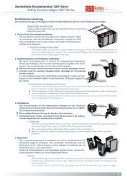
7. Mechanical mounting<br />
Mechanical mounting of the safet�� rela�� is to be performed professionall�� at a suitable mounting<br />
location.<br />
The provided assembl�� instruction are recommendations onl��. The actual arrangement of the<br />
individual components depends on the design of the gate in question and the conditions at the<br />
installation site.<br />
The switching unit must not be mounted in the immediate vicinit�� of strong sources of heat.<br />
The switching unit ma�� be mounted in an�� orientation. To prevent moisture penetration, it should,<br />
however, be installed so that the cable conduits point downward.<br />
The procedure for constructing the <strong>ISK</strong> s��stem can be found in the separate assembl�� instructions.