SK 37 / SK 38 - ASO Safety
SK 37 / SK 38 - ASO Safety
SK 37 / SK 38 - ASO Safety

Create successful ePaper yourself
Turn your PDF publications into a flip-book with our unique Google optimized e-Paper software.
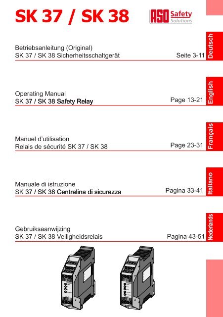
<strong>SK</strong> <strong>37</strong> / <strong>SK</strong> <strong>38</strong><br />
Betriebsanleitung (Original)<br />
<strong>SK</strong> <strong>37</strong> / <strong>SK</strong> <strong>38</strong> Sicherheitsschaltgerät Seite 3-11 Deutsch<br />
Operating Manual<br />
<strong>SK</strong> <strong>37</strong> / <strong>SK</strong> <strong>38</strong> Sa�et�� Sa�et�� Sa�et�� Rela�� Rela�� Rela�� Rela��<br />
Manuel d’utilisation<br />
Relais de sécurité <strong>SK</strong> <strong>37</strong> / <strong>SK</strong> <strong>38</strong><br />
Manuale di istruzione<br />
<strong>SK</strong> <strong>37</strong> / <strong>SK</strong> <strong>38</strong> �entralina �entralina �entralina di sicurezza<br />
B1 B2 A1 A2<br />
Z1 Z2 T1 T2<br />
Power<br />
CH 1<br />
CH 2<br />
Aux Relay<br />
<strong>SK</strong> <strong>37</strong><br />
X1 X2 Y1 Y2<br />
13 14 23 24<br />
S e t t i n g s<br />
1 2 3 4 5 6<br />
B1 B2 A1 A2<br />
Z1 Z2 T1 T2<br />
Power<br />
CH 1<br />
CH 2<br />
Aux Rel 1<br />
Aux Rel 2<br />
<strong>SK</strong> <strong>38</strong><br />
X1 X2 Y1 Y2<br />
13 14 31 32<br />
S e t t i n g s<br />
1 2 3 4 5 6<br />
Page 13-21<br />
Page 23-31<br />
Pagina 33-41<br />
Gebruiksaanwijzing<br />
<strong>SK</strong> <strong>37</strong> / <strong>SK</strong> <strong>38</strong> Veiligheidsrelais Pagina 43-51<br />
Nederlands<br />
English<br />
Français<br />
Italiano
2<br />
Übergabedokumentation / Documentation / Documentation<br />
de datation / Documentazione di consegna / Documentatie<br />
Anlagenbeschreibung / Description / Description du système / Descrizione impianto /<br />
Beschrijving van de installatie<br />
Anlagenart / T��pe o� plant / Sorte du s��stème / Tipo d’impianto / T��pe installatie<br />
Hersteller / Manu�acturer / Fabricant / Produttore / Fabrikant<br />
Seriennummer / Serial number / Numéro de série / Numero di serie / Seriennummer<br />
Datum der Inbetriebnahme / �ommissioning date / Date de mise en marche / Data della messa in<br />
�unzione / Datum van de ingebruikname<br />
Au�stellort / Site o� installation / Lieu de montage / Luogo d’installazione / Opstellingsplaats<br />
Verwendete Steuerung / �ontrol unit / �ommande utilisée / �entralina di comando adottata /<br />
Gebruikte besturing<br />
Zusatzkomponenten / Additional components / �omposants supplémentaires / �omponenti<br />
ausiliari / Bijkomende componenten<br />
Funktionsprüfung / Functional test / Contrôle de fonction / Controllo funzionale / Functiecontrole<br />
Sicherheitssensoren reagieren au� Betätigung / Sa�et�� sensor response to actuation /<br />
Le senseur de sécurité réagit à l’actionnement / Il sensore di sicurezza reagisce all’azionamento /<br />
Veiligheidssensor reageert op activering<br />
Sicherheitssensoren reagieren au� Zuleitungsunterbrechung / Sa�et�� sensor response to<br />
suppl�� line interruption / Le senseur de sécurité réagit à l’interruption de l’alimentation /<br />
Il sensore di sicurezza reagisce all’interruzione di collegamento Veiligheidssensor reageert<br />
op onderbreking van de toevoerleiding<br />
Name der aus�ührenden Firma / Owner / Nom de la société exécutrice / Nome della ditta<br />
esecutrice / Naam van de uitvoerende firma<br />
Name des Installateurs / Installer / Nom de l’installateur / Nome dell’installatore / Naam van de<br />
installateur<br />
Datum / Date / Date / Data / Datum Unterschri�t / Signature / Signature / Firma /<br />
Handtekening<br />
ok<br />
ok
<strong>SK</strong> <strong>37</strong> / <strong>SK</strong> <strong>38</strong> Sicherheitsschaltgerät<br />
1. Inhaltsverzeichnis<br />
1. Inhaltsverzeichnis . . . . . . . . . . . . . . . . . . 3<br />
2. Allgemeine Sicherheitsbestimmungen und<br />
Schutzmaßnahmen . . . . . . . . . . . . . . . . . 3<br />
3. Allgemeines . . . . . . . . . . . . . . . . . . . . . 4<br />
4. Bestimmungsgemäße Verwendung . . . . . . . . . 4<br />
5. Geräteübersicht . . . . . . . . . . . . . . . . . . . 5<br />
5.1 Signalanzeigen . . . . . . . . . . . . . . . . . . . . . . 5<br />
5.2 Anschlussklemmen . . . . . . . . . . . . . . . . . . . . 5<br />
5.3 Aus�ührungen . . . . . . . . . . . . . . . . . . . . . . . 5<br />
5.4 Betriebsarten . . . . . . . . . . . . . . . . . . . . . . . 6<br />
5.5 DIP-Schalter zum Einstellen der Betriebsart . . . . . . . 6<br />
6. Mechanische Be�estigung. . . . . . . . . . . . . . 7<br />
7. Elektrische Inbetriebnahme . . . . . . . . . . . . . 7<br />
7.1 Voraussetzungen . . . . . . . . . . . . . . . . . . . . . 7<br />
7.2 Elektrischer Anschluss . . . . . . . . . . . . . . . . . . 8<br />
7.3 Anschluss von mehreren Signalgebern . . . . . . . . . . 8<br />
7.4 Besonderheiten der Sicherheitshalbleiterausgänge. . . . 8<br />
7.5 Funktionsprü�ung . . . . . . . . . . . . . . . . . . . . . 9<br />
8. Fehlerdiagnose . . . . . . . . . . . . . . . . . . . 9<br />
9. Anwendungsbeispiele . . . . . . . . . . . . . . . . 10<br />
10. Außerbetriebnahme und Entsorgung . . . . . . . . 10<br />
11. Technische Daten . . . . . . . . . . . . . . . . . . 10<br />
12. EG Kon�ormitätserklärung. . . . . . . . . . . . . . 11<br />
Technische und betriebsrelevante Änderungen zu den in dieser Dokumentation<br />
aufgeführten Produkten und Geräten sind jederzeit auch ohne<br />
Vorankündigung vorbehalten.<br />
2. Allgemeine Sicherheitsbestimmungen und<br />
Schutzmaßnahmen<br />
• Hersteller und Benutzer der Anlage / Maschine, an der die Schutzeinrichtung verwendet wird, sind<br />
da�ür verantwortlich, alle geltenden Sicherheitsvorschri�ten und -regeln in eigener Verantwortung<br />
abzustimmen und einzuhalten.<br />
• Die Schutzeinrichtung garantiert in Verbindung mit der übergeordneten Steuerung eine �unktionale<br />
Sicherheit, nicht aber die Sicherheit der gesamten Anlage / Maschine. Vor dem Einsatz des<br />
Gerätes ist deshalb eine Sicherheitsbetrachtung der gesamten Anlage / Maschine notwendig.<br />
• Die Bedienungsanleitung muss ständig am Einsatzort der Schutzeinrichtung ver�ügbar sein.<br />
Sie ist von jeder Person, die mit der Bedienung, Wartung oder Instandhaltung der Schutzeinrichtung<br />
beau�tragt wird, gründlich zu lesen und anzuwenden.<br />
Deutsch<br />
3
Deutsch<br />
4<br />
<strong>SK</strong> <strong>37</strong> / <strong>SK</strong> <strong>38</strong> Sicherheitsschaltgerät<br />
• Die Installation und Inbetriebnahme der Schutzeinrichtung dar� nur durch Fachpersonal er�olgen,<br />
die mit dieser Betriebsanleitung und den geltenden Vorschri�ten über Arbeitssicherheit und<br />
Un�allverhütung vertraut sind. Die Hinweise in dieser Anleitung sind unbedingt zu beachten und<br />
einzuhalten.<br />
• Elektrische Arbeiten dür�en nur von Elektro�achkrä�ten durchge�ührt werden.<br />
• Sicherheitsvorschri�ten der Elektrotechnik und der Beru�sgenossenscha�t sind zu beachten.<br />
• Bei Arbeiten am Schaltgerät ist dieses spannungs�rei zu schalten und au� Spannungs�reiheit zu<br />
prü�en und gegen Wiedereinschalten zu sichern.<br />
• Das Schaltgerät enthält keine vom Anwender zu wartende Bauteile. Durch eigenmächtige<br />
Umbauten bzw. Reparaturen am Schaltgerät erlischt jegliche Gewährleistung und Ha�tung des<br />
Herstellers.<br />
• Hil�sausgänge dür�en keine sicherheitsgerichteten Funktionen aus�ühren. Sie sind nicht ein�ehlersicher<br />
und werden auch nicht durch Testung überprü�t.<br />
Für die normenkonforme Auslegung des Sicherheitssystems muss die Anlage<br />
von Sachkundigen in geeigneten Zeitabständen auf korrekte Funktion geprüft<br />
werden. Die Prüfung muss in jederzeit nachvollziehbarer Weise dokumentiert<br />
werden.<br />
3. Allgemeines<br />
Die Schaltgeräte <strong>SK</strong> <strong>37</strong> und <strong>SK</strong> <strong>38</strong> dienen zur Auswertung von Sicherheitskontaktmatten, sowie<br />
zur Absicherung von Quetsch- und Scherstellen durch Sicherheitskontaktleisten und Sicherheitsbumpern.<br />
Die Schaltgeräte sind nach EN ISO 1<strong>38</strong>49-1 „Sicherheitsbezogene Teile von Steuerungen“ �ür Kat. 3<br />
Per�ormance Level d ausgelegt und baumustergeprü�t. Für die Einhaltung der Kat. 3 sind die Schaltgeräte<br />
redundant und diversitär mit zwei unabhängigen Schaltelementen au�gebaut, von denen der<br />
Halbleiterschalter �ortlau�end au� seine Schalt�ähigkeit hin getestet wird.<br />
Die Ruhestromüberwachung der Signalgeber wird durch integrierte Abschlusswiderstände in den<br />
Signalgebern ermöglicht. Fließt der Soll-Ruhestrom, so ist der Ausgang durchgesteuert. Wird der<br />
Signalgeber betätigt oder der Signalgeberstromkreis unterbrochen, ö��nen die Schaltkontakte.<br />
Der Überwachungszustand der Signalgeber und der Hil�sausgänge, sowie die angelegte Betriebsspannung<br />
werden durch LED‘s angezeigt.<br />
4. Bestimmungsgemäße Verwendung<br />
Die bestimmungsgemäße Verwendung des Schaltgerätes, ist der Einsatz als Schutzeinrichtung in<br />
Verbindung mit Sicherheitskontaktmatten, Sicherheitsbumpern und Sicherheitskontaktleisten mit<br />
8,2 kΩ Widerstand zur Ruhestromüberwachung.<br />
Ein anderer oder darüber hinausgehender Einsatz ist nicht bestimmungsgemäß. Für Schäden, die aus<br />
nicht bestimmungsgemäßen Verwendungen entstehen, übernimmt der Hersteller keine Ha�tung.<br />
Der Einsatz bei Sonderanwendungen bedar� einer Freigabe vom Hersteller.
5. Geräteübersicht<br />
5.1 Signalanzeige<br />
LED Power grün / rot<br />
Versorgungsspannung 24 V liegt an (grün)<br />
Fehler bei interner Selbsttestung (rot)<br />
LED CH 1 gelb / rot<br />
Signalgeber betätigt (gelb) oder<br />
Signalgeberstromkreis unterbrochen (rot)<br />
LED CH 2 gelb / rot<br />
Signalgeber betätigt (gelb) oder<br />
Signalgeberstromkreis unterbrochen (rot)<br />
LED AUX. 1 orange<br />
Meldeausgang geschaltet<br />
LED AUX. 2 orange<br />
(nur <strong>SK</strong> <strong>38</strong>)<br />
Meldeausgang geschaltet<br />
5.2 Anschlussklemmen<br />
Y1 Y2 -- --<br />
X1 X2 31 32<br />
Power<br />
CH 1<br />
CH 2<br />
Aux Relay<br />
<strong>SK</strong> <strong>37</strong><br />
0V +24V 13 14<br />
S11 S12 Z1 Z2<br />
+24V 0V Versorgungsspannung 24 V D�, ±10%<br />
X1 X2 Anschluss Signalgeber 1<br />
Y1 Y2 Anschluss Signalgeber 2<br />
13 14 Sicherheitsschaltkontakt 1<br />
Y1 Y2 41 42<br />
X1 X2 31 32<br />
Power<br />
CH 1<br />
CH 2<br />
Aux Rel 1<br />
Aux Rel 2<br />
<strong>SK</strong> <strong>38</strong><br />
0V +24V 24 14<br />
S11 S12 Z1 Z2<br />
(13 = Eingang +24 V D�, +10% / -50%, bei <strong>SK</strong> <strong>38</strong> intern verbunden)<br />
24 Sicherheitsschaltkontakt 2 (nur bei <strong>SK</strong> <strong>38</strong>)<br />
31 32 Schaltkontakt Meldeausgang 1<br />
41 42 Schaltkontakt Meldeausgang 2 (nur bei <strong>SK</strong> <strong>38</strong>)<br />
Z1 Z2 Anschluss manuelle Rücksetzung/Wiederanlau� (Taster NO; optional)<br />
S11 S12 Kodiereingänge Modus<br />
5.3 Ausführungen<br />
Ausführung <strong>SK</strong> <strong>37</strong>-72 <strong>SK</strong> <strong>38</strong>-72<br />
sicherheitsgerichtete<br />
Eingänge<br />
sicherheitsgerichtete<br />
Ausgänge<br />
2x 2x<br />
1x 2x<br />
(2. Kontakt intern<br />
au� +24V gebrückt)<br />
Meldeausgänge 1x 2x<br />
Deutsch<br />
5
Deutsch<br />
6<br />
<strong>SK</strong> <strong>37</strong> / <strong>SK</strong> <strong>38</strong> Sicherheitsschaltgerät<br />
5.4 Betriebsarten<br />
Automatischer Reset (S11 S12 gebrückt)<br />
Nach Beseitigung einer Störung eines Signalgeberstromkreises oder nach Spannungsaus�all gibt<br />
das Schaltgerät den Ausgang automatisch wieder �rei.<br />
Während der Störung leuchten die korrespondierenden LED‘s CH1 bzw. CH2 dauerha�t.<br />
Fehlerselbsthaltung - manueller Reset (S11 S12 unbeschaltet)<br />
Nach Beseitigung einer Störung eines Signalgeberstromkreises oder nach Spannungsaus�all gibt das<br />
Schaltgerät den oder die Ausgänge erst wieder �rei, wenn die Kontakte Z1 und Z2 mit einem Taster<br />
geschlossen werden. Ein automatisches Wiederanlau�en ist so ausgeschlossen. Ein dauerha�tes<br />
Überbrücken der Kontakte Z1 Z2 �ührt nicht zu einer automatischen Rücksetzung.<br />
Die korrespondierenden LED CH1 bzw. CH2 leuchten während der Störung dauerha�t und blinken<br />
im Anschluss so lange, bis der Fehler durch Drücken des Tasters zurückgesetzt wurde.<br />
5.5 DIP-Schalter zum Einstellen der Betriebsart<br />
An der rechten Gehäuseseite befinden sich 6 DIP-Schalter, von denen beim <strong>SK</strong> <strong>37</strong> die ersten 4 und<br />
beim <strong>SK</strong> <strong>38</strong> alle 6 belegt sind. Die Werkseinstellungen sind im Text unterstrichen.<br />
S1 Meldeausgang 1 blinkt bei RLU („On“) / blinkt nicht („O��“)<br />
S2 Meldeausgang 1 ist im Ruhezustand aktiv („On“) / inaktiv („O��“)<br />
S3 Modus Meldeausgang 1: RL („On“) / RLU („O��“)<br />
S4 <strong>SK</strong> <strong>37</strong>: Meldeausgang reagiert au� �H1 und �H2 („On) / au� �H1 („O��)<br />
<strong>SK</strong> <strong>38</strong>: Meldeausgang 2 blinkt bei RLU („On“) / blinkt nicht („O��“)<br />
S5 Meldeausgang 2 ist im Ruhezustand aktiv („On“) / inaktiv („O��“)<br />
S6 Modus Hil�sausgang 2: RL („On“) / RLU („O��“)<br />
Meldeausgang unverzögert (RLU, S3 = „off“ bzw. S6 = „off“)<br />
In dieser Betriebsart wird der entsprechende Meldeausgang unverzögert aktiviert, wenn ein beliebiger<br />
Fehler am entsprechenden Kanal signalisiert wird. Der Meldeausgang kann mit S2 bzw. S5 zwischen<br />
Ö��ner und Schließer umgeschaltet werden („On“ = Ö��ner), wobei der Ausgang im stromlosen Zustand<br />
des Schaltgerätes immer inaktiv ist.<br />
Meldeausgang unverzögert blinkend (RLU, S1 = „on“, S3 = „off“ bzw. S4 = „on“, S6 = „off“)<br />
Mit S1 kann ein Blinken des Meldeausgangs s��nchron zu den LED‘s aktiviert werden (werksmäßige<br />
Einstellung von S1 bzw. S4 = „o��“).<br />
Sicherheitsausgang (s��mbolisch)<br />
Meldeausgang (s��mbolisch)
Meldeausgang verzögert RL (S3 = „on“, S1 = „off“ bzw. S6 = „on“, S4 = „off“)<br />
In dieser Betriebsart wird der entsprechende Meldeausgang um 0,5 Sekunde verzögert aktiviert und<br />
bleibt dann �ür max. 3 Sekunden aktiv, wenn ein Fehler signalisiert wird. Der Meldeausgang kann<br />
mit S2 zwischen Ö��ner und Schließer umgeschaltet werden, wobei der Ausgang im stromlosen<br />
Zustand immer inaktiv ist.<br />
S1 bzw. S4 (nur bei <strong>SK</strong> <strong>38</strong>) muss sich in Schalterstellung „Off“ befinden (werksmäßige Einstellung),<br />
sonst bleibt der Meldeausgang dauerha�t inaktiv.<br />
0,5 s 3 s<br />
6. Mechanische Befestigung<br />
Sicherheitsausgang (s��mbolisch)<br />
Meldeausgang (s��mbolisch)<br />
Das Schaltgerät muss fachgerecht befestigt werden:<br />
- In einem staub- und feuchtigkeitsgeschütztem Schaltschrank oder Gehäuse.<br />
- Mit einer Schutzart von mindestens IP54.<br />
- Auf einer 35 mm DIN-Tragschiene nach EN 50 022.<br />
Das Schaltgerät darf nicht in unmittelbarer Nähe von starken Wärmequellen montiert werden.<br />
Die Einbaulage des Schaltgerätes ist beliebig.<br />
7. Elektrische Inbetriebnahme<br />
Der Anschluss an die falschen Klemmen kann das Schaltgerät zerstören.<br />
7.1 Voraussetzungen<br />
• Das Schaltgerät ermöglicht den Betrieb an einer Versorgungsspannung von 24 V D� ±10%.<br />
• Alle angelegten Spannungen müssen den An�orderungen �ür Schutzkleinspannung (SELV)<br />
entsprechen. Die Ausgänge sind von der Versorgungsspannung nicht galvanisch<br />
getrennt.<br />
• Die Meldekontakte dienen lediglich als Hil�skontakte (Signalisierung, Anzeige etc.) und dür�en<br />
keine Sicherheits�unktionen aus�ühren.<br />
• Leitungen die im Freien oder außerhalb vom Schaltschrank verlegt werden, müssen entsprechend<br />
geschützt werden.<br />
Deutsch<br />
7
Deutsch<br />
8<br />
<strong>SK</strong> <strong>37</strong> / <strong>SK</strong> <strong>38</strong> Sicherheitsschaltgerät<br />
7.2 Elektrischer Anschluss<br />
• Versorgungsspannung 24 V D� an die Klemmen +24 V 0 V anschließen.<br />
• Signalgeber an die Klemmen X1 X2 bzw. Y1 Y2 anschließen.<br />
• Den zu überwachenden Steuerstromkreis an die Klemmen 13 (an +24 V) 14 bzw. 24 (nur <strong>SK</strong> <strong>38</strong>)<br />
anschließen. Die Kabel sind so zu verlegen, dass eine Überbrückung der Sicherheitskontakte z. B.<br />
durch einen Kurzschluss zwischen den beiden Anschlussdrähten ausgeschlossen werden kann.<br />
• Für den automatischen Reset / Wiederanlau�, sind die Klemmen S11 S12 zu brücken (werkseitige<br />
Einstellung: manuelle Rücksetzung, S11 S12 ungebrückt) und der Rücksetztaster an die Klemmen<br />
Z1 Z2 anzuschließen.<br />
Nach er�olgreicher Inbetriebnahme ist der Sicherheits-Ausgang 13 14 bzw. 24 angesteuert<br />
(„geschlossen“). Eine Betätigung des Signalgebers bewirkt ein Ö��nen der Ausgangsschaltelemente<br />
und eine Reaktion des Meldeausganges entsprechend der DIP-Schalter-Konfiguration.<br />
Auch während die Sicherheitsausgänge angesteuert sind, er�olgt eine �ortlau�ende Testung der<br />
Schalt�ähigkeit. Hierzu wird der Halbleiter-Ausgangsschalter mehr�ach pro Sekunde �ür weniger als<br />
1ms ausgeschaltet und das Verhalten am Ausgang beobachtet. Wenn die Spannung nicht au� 0 V<br />
zurückgeht, schaltet das Gerät dauerha�t ab und lässt sich nur durch Ab- und Wiedereinschalten der<br />
Spannungsversorgung zurücksetzen. Die Power-LED leucht in diesem Fall rot.<br />
Diese dauerha�te Abschaltung tritt auch dann au�, wenn die Spannung durch die Art der Anschaltung<br />
nicht zusammenbrechen kann (z. B. durch kapazitive Elemente).<br />
7.3 Anschluss von mehreren Signalgebern<br />
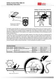
<strong>ASO</strong>-Signalgeber dürfen nicht parallel geschaltet werden.<br />
An dem Signalgebereingängen X1 X2 bzw. Y1 Y2 können ein oder mehrere Signalgeber (z. B.<br />
Sicherheitskontaktleisten) angeschlossen werden. Hier�ür können die einzelnen Signalgeber in<br />
Serie geschaltet werden.<br />
Ein nicht benutzter Eingang kann mit einem 8,2 kΩ-Widerstand überbrückt werden.<br />
Es können maximal 5 Signalgeber mit einer Gesamtkabellänge von max. 25 m in Serie geschaltet<br />
werden.<br />
Vor dem Anschließen der in Serie geschalteten Signalgeber ist es emp�ehlenswert, den Widerstands-<br />
wert der Verschaltung auszumessen. Bei unbetätigter <strong>SK</strong>L muss der Widerstand 8,2 kΩ ± 100 Ω<br />
betragen. Ist die <strong>SK</strong>L betätigt, dar� der Widerstand 500 Ω nicht überschreiten.<br />
Signalgeber 1<br />
Signalgeber 2<br />
Signalgeber „n“<br />
X1 2<br />
X2<br />
2<br />
2<br />
Bild 1: Verschaltung mehrerer Signalgeber, hier am Beispiel Sicherheitskontaktleiste<br />
7.4 Besonderheiten der Sicherheitshalbleiterausgänge (OSSD)<br />
Die elektronischen Sicherheitshalbleiterausgänge des Schaltgerätes werden im lau�enden Betrieb<br />
ständig getestet. Dazu wird der Ausgang z��klisch alle 0,8 Sekunden �ür eine Zeit von etwa 1,2 ms<br />
abgeschaltet und das Abschaltverhalten überprü�t. Diese Unterbrechungen dür�en von der nach-<br />
geordneten Steuerung nicht als An�orderung der Sicherheit gewertet werden.<br />
Ebenso muss ein Sicherheitshalbleiterausgang mindestens 5ms lang aktiv sein, bevor die Steuerung<br />
dies als Freigabe werten dar�. In dieser Zeit wird der Ausgang durch die Elektronik des Schaltgerätes<br />
au� Kurzschlüsse getestet.<br />
2
7.5 Funktionsprüfung<br />
Nach entsprechendem Anschluss aller elektrischen Verbindungen und Einschalten der Versorgungsspannung<br />
muss die Anlage / Maschine au� korrekte Funktion überprü�t werden:<br />
• Betätigen Sie die Signalgeber der Reihe nach.<br />
• Kontrollieren Sie die entsprechenden Reaktionen des Schaltgerätes.<br />
Das Sicherheitss��stem muss in geeigneten Zeitabständen von Sachkundigen geprü�t werden.<br />
Die Prü�ung muss in jederzeit nachvollziehbarer Weise dokumentiert werden.<br />
Die An�orderungen des Anlagen- / Maschinenherstellers sind zu berücksichtigen und einzuhalten.<br />
8. Fehlerdiagnose<br />
Bei korrekter Verdrahtung und Anlegen der Versorgungsspannung dar� nur die grüne LED leuchten.<br />
Bei Aufleuchten der gelben oder roten LED‘s ist ein Fehler im S��stem vorhanden, der sich mit Hil�e<br />
der LED‘s eingrenzen lässt. Die orangen LED‘s �ür die Meldeausgänge leuchten in Abhängigkeit<br />
der Einstellungen an den DIP-Schaltern.<br />
*<br />
keine LED<br />
leuchtet<br />
LED Fehler Fehlerbeseitigung<br />
gelbe LED<br />
leuchtet<br />
(CH1 bzw. CH2)<br />
rote LED<br />
leuchtet<br />
(CH1 bzw. CH1)<br />
rote LED<br />
leuchtet<br />
(Power)<br />
Versorgungsspannung fehlt, zu gering<br />
oder falsch angeschlossen<br />
Signalgeber fehlerhaft angeschlossen,<br />
betätigt oder defekt<br />
Signalgeber nicht angeschlossen, fehlerhaft<br />
angeschlossen oder defekt<br />
Am Sicherheitsausgang liegt eine fremdgespeiste<br />
Spannung an oder es wurde<br />
ein interner Fehler erkannt.<br />
Anschlüsse und Versorgungsspannung überprüfen:<br />
- 24 V DC an Klemmen +24 V 0 V<br />
- Polarität richtig? +24 V an Klemme +24 V<br />
Toleranzbereich: ±10%<br />
- Anschlüsse der entsprechenden Signalgeber<br />
überprüfen (abgequetschte Zuleitungen, brüchige<br />
Zuleitungen etc.)<br />
- Signalgeber überprüfen*<br />
- Anschlüsse der entsprechenden Signalgeber<br />
überprüfen (abgequetschte Zuleitungen, brüchige<br />
Zuleitungen etc.)<br />
- Signalgeber überprüfen*<br />
<strong>SK</strong> <strong>37</strong>: Prüfen, ob +24 V an Klemme 13 angeschlossen<br />
ist; Ausgangsverschaltung überprüfen: Es<br />
dürfen nur Stromverbraucher (z. B. Schütze) an 0 V<br />
angeschaltet werden. Testweise Schaltgerät ohne<br />
Anschluss am Ausgang (14 bzw. 24) betreiben.<br />
Wenn sich der Fehler nicht beheben lässt, Gerät zur<br />
Überprüfung einschicken.<br />
Liegt der Fehler nicht in der Verdrahtung, kann die Funktion der Elektronik durch Belegung des<br />
Signalgeber-Eingangs am Schaltgerät (Klemmen X1 X2 bzw. Y1 Y2) mit einem 8,2 kΩ Widerstand<br />
überprü�t werden. Arbeitet danach die Elektronik einwand�rei, muss der Signalgeber mit einem<br />
Widerstandsmessgerät überprü�t werden. Hier�ür muss die Verbindung des Signalgebers zum<br />
Schaltgerät au�getrennt und mit einem Widerstandsmessgerät verbunden werden. Bei unbetätigtem<br />
Signalgeber muss der Widerstand 8,2 kΩ ±100 Ω betragen. Ist der Signalgeber betätigt, dar� der<br />
Widerstand 500 Ω �nicht überschreiten.<br />
Deutsch<br />
9
Deutsch<br />
10<br />
<strong>SK</strong> <strong>37</strong> / <strong>SK</strong> <strong>38</strong> Sicherheitsschaltgerät<br />
9. Anwendungsbeispiele<br />
Schaltbilddarstellung in spannungslosem Zustand.<br />
Sensor nicht betätigt.<br />
Anwendungsbeispiel 1<br />
Sicherheitsgerichtete Überwachung von zwei Signal-<br />
geberkreisen mit Start�reigabe über Start-Taster mit<br />
einem Kanal eines <strong>SK</strong> <strong>38</strong>. Zur Funktionskontrolle des<br />
zwangsge�ührten Lastschützes K1 werden dessen<br />
��nerkontakte in den Start-Kreis (Z1 Z2) verschaltet.<br />
Anwendungsbeispiel 2<br />
Sicherheitsgerichtete Überwachung von zwei Signal-<br />
geberkreisen zum Stillsetzen eines Antriebes mit<br />
automatischem Wiederanlau� mit einem <strong>SK</strong> <strong>37</strong>.<br />
Der Meldeausgang ist mit der SPS-Steuerung der<br />
Anlage verschaltet (z.B. zur Visualisierung).<br />
11. Technische Daten<br />
Versorgungsspannung<br />
Niederspannung: U 24 V D� D� ±10 % (SELV)<br />
E<br />
Leistungsaufnahme<br />
P = 1 W 24 V D�<br />
E_max<br />
Zulassungen<br />
EN ISO 1<strong>38</strong>49-1:2008 Kategorie 3 PL d<br />
(MTTFd 355 Jahre, D� 90%)<br />
(angenommene 52.560 Z��klen)<br />
Abschlusswiderstand Signalgeber<br />
Nominalwert R = 8,2 kΩ<br />
nom<br />
oberer Schaltwert R > 12,5 kΩ<br />
AO<br />
unterer Schaltwert R < 4,5 kΩ<br />
AU<br />
Sicherheitsausgänge<br />
max. Schaltspannung 10 .. 26,4 V D�<br />
max. Schaltstrom 2 A D�<br />
Elektr. Lebensdauer 10 5 Betätigungen<br />
Zertifikat Nr.: 44 780 10 5555564<br />
Prüfbericht Nr.: 10 205 555564-002<br />
+24VDC<br />
0VDC<br />
+24VDC<br />
0VDC<br />
A1<br />
8,2 ΚΩ<br />
X1 X2<br />
1/2 <strong>SK</strong> <strong>38</strong>-72<br />
A2 31<br />
A1<br />
<strong>SK</strong> <strong>37</strong>-72<br />
8,2 ΚΩ<br />
32<br />
X1 X2 Y1 Y2<br />
A2 31<br />
32<br />
Start<br />
S11 S12 Z1 Z2<br />
K1 A1<br />
Schaltzeiten Sicherheitsausgang<br />
Reaktionszeit < 2 ms<br />
Freischaltzeit 0,3 s ±0,1 s<br />
Schaltzeiten Meldeausgang RL-Funktion<br />
Reaktionszeit 0,5 s ±0,2 s<br />
Freischaltzeit 3 s ±1 s<br />
max. Schaltspannung 50 V A�/D�<br />
max. Schaltstrom 2 A A�/D�<br />
Bei der RLU-Funktion schaltet der Melde-<br />
ausgang s��nchron zu der Betätigung des<br />
Signalgebers.<br />
Gehäuse<br />
Pol��amid PA 6.6<br />
selbstverlöschend nach UL 94-V2<br />
Abmessungen (HxBxT) 99 x 22,5 x 114 mm<br />
Schutzart IP20<br />
8,2 ΚΩ<br />
E0.00<br />
PLC<br />
Gewicht 160 g<br />
13<br />
L1 L2 L3<br />
K1 1 3 5<br />
2 4 6<br />
Temperaturbereich -20 °� bis +55 °�<br />
K1<br />
14<br />
A2<br />
K1 A1<br />
Querschnitt Anschlussleitungen<br />
0,75-1,5 mm 2 ein-, oder �eindrähtige Leitung<br />
14<br />
A2<br />
M<br />
L1 L2 L3<br />
K1 1 3 5<br />
10. Außerbetriebnahme und Entsorgung<br />
Die von <strong>ASO</strong> hergestellten Produkte sind ausschließlich �ür den gewerblichen Gebrauch (B2B)<br />
vorgesehen. Nach Nutzungsbeendigung sind die Produkte gemäß allen örtlichen, regionalen und<br />
nationalen Vorschri�ten zu entsorgen. <strong>ASO</strong> nimmt die Produkte auch gern zurück und entsorgt diese<br />
ordnungsgemäß.<br />
2 4 6<br />
M
12. EG Konformitätserklärung<br />
Hiermit erklären wir, dass die nach�olgend bezeichneten Produkte der Baureihe:<br />
<strong>SK</strong> <strong>37</strong>-72 (Artikelnummer 203305, Format Seriennummer ����mmnnnnn)<br />
<strong>SK</strong> <strong>38</strong>-72 (Artikelnummer 203306, Format Seriennummer ����mmnnnnn)<br />
Sicherheitsschaltgerät zur Kombination mit Schaltleisten, Schaltmatten und<br />
Schaltpu��ern zur Vermeidung von Ge�ahren an Quetsch- und Scherstellen au�grund<br />
ihrer Konzipierung und Bauart sowie in der von uns in Verkehr gebrachten<br />
Aus�ührung, den einschlägigen grundlegenden Sicherheits- und Gesundheitsan�orderungen<br />
der nach�olgenden EG-Richtlinien entspricht:<br />
EG - Maschinenrichtlinie 2006/42/EG<br />
EN ISO 1<strong>38</strong>49-1:2008<br />
EN ISO 1<strong>38</strong>49-2:2008<br />
EN 61000-6-2:2005<br />
EN 61000-6-3:2007<br />
EG - Baumusterprüfung<br />
Notified Body 0044<br />
TÜV NORD �ERT GmbH<br />
Langemarckstraße 20<br />
D-45141 Essen<br />
EG Baumusterprü�bescheinigung Nr.: 44 205 10 555564<br />
Diese Kon�ormitätserklärung entbindet den Konstrukteur/Hersteller der Maschine<br />
nicht von seiner Pflicht, die Konformität der gesamten Maschine, an der dieses<br />
Produkt angebracht wird, entsprechend der EG-Richtlinie sicherzustellen.<br />
Hersteller und Dokumentenbevollmächtigter:<br />
<strong>ASO</strong>, Antriebs- und Steuerungstechnik GmbH,<br />
Am Grarock 8, D-33154 Salzkotten<br />
Salzkotten, den XX.XX.2010<br />
……………………<br />
Helmut Friedrich<br />
(Geschä�ts�ührer und Dokumentenbevollmächtigter)<br />
11
<strong>SK</strong> <strong>37</strong> / <strong>SK</strong> <strong>38</strong> <strong>Safety</strong> Relay<br />
1. Contents<br />
1. �ontents. . . . . . . . . . . . . . . . . . . . . . . 13<br />
2. General sa�et�� regulations and protective measures 13<br />
3. General . . . . . . . . . . . . . . . . . . . . . . . 14<br />
4. Proper use. . . . . . . . . . . . . . . . . . . . . . 14<br />
5. Device overview. . . . . . . . . . . . . . . . . . . 15<br />
5.1 Signal indicators. . . . . . . . . . . . . . . . . . . . . . 15<br />
5.2 �onnection terminals . . . . . . . . . . . . . . . . . . . 15<br />
5.3 Versions . . . . . . . . . . . . . . . . . . . . . . . . . . 15<br />
5.4 Operating modes . . . . . . . . . . . . . . . . . . . . . 16<br />
5.5 DIP switches �or setting the operating mode . . . . . . . 16<br />
6. Mechanical mounting . . . . . . . . . . . . . . . . 17<br />
7. Electrical commissioning . . . . . . . . . . . . . . 17<br />
7.1 Prerequisites . . . . . . . . . . . . . . . . . . . . . . . 17<br />
7.2 Electrical connection . . . . . . . . . . . . . . . . . . . 18<br />
7.3 �onnection o� multiple sensors . . . . . . . . . . . . . . 18<br />
7.4 Special �eatures o� the sa�et��-related semiconductor<br />
outputs . . . . . . . . . . . . . . . . . . . . . . . . . . 18<br />
7.5 Functional test. . . . . . . . . . . . . . . . . . . . . . . 19<br />
8. Error diagnosis . . . . . . . . . . . . . . . . . . . 19<br />
9. Examples o� use. . . . . . . . . . . . . . . . . . . 20<br />
10. Taking out o� service and disposal . . . . . . . . . 20<br />
11. Technical specifications . . . . . . . . . . . . . . . 20<br />
12. E� declaration o� con�ormit�� . . . . . . . . . . . . 21<br />
We reserve the right to make technical and operationally relevant changes<br />
to the products and devices described in this documentation at any time<br />
and without prior notice.<br />
2. General safety regulations and protective measures<br />
• The manu�acturer and users o� the plant / machine on which the protection is being used are<br />
responsible �or implementing and �ollowing all applicable sa�et�� regulations and rules.<br />
• When used in conjunction with the higher-order controller, the protection guarantees �unctional<br />
sa�et��, but not the sa�et�� o� the entire plant / machine. The sa�et�� o� the entire plant / machine<br />
must, there�ore, be assessed be�ore using the device.<br />
• The operating instructions must alwa��s be available at the place o� installation o� the protection.<br />
The�� must be read thoroughl�� and observed b�� all persons involved in the operation, maintenance<br />
and servicing o� the protection.<br />
English<br />
13
English<br />
14<br />
<strong>SK</strong> <strong>37</strong> / <strong>SK</strong> <strong>38</strong> <strong>Safety</strong> Relay<br />
• The protection must onl�� be installed and commissioned b�� pro�essionals �amiliar with these<br />
operating instructions and the applicable operational sa�et�� and accident prevention regulations.<br />
All o� the instructions provided in these operating instructions must be observed and �ollowed.<br />
• All electrical work must onl�� be per�ormed b�� skilled electricians.<br />
• All relevant electrical engineering and Emplo��er's Liabilit�� Insurance Association sa�et�� regulations<br />
must be observed.<br />
• During work on the switching unit, it is to be switched to zero potential and checked to ensure<br />
that it is at zero potential and protected against being restarted.<br />
• The switching unit does not contain an�� components that require servicing b�� the user. Unauthorised<br />
conversions and repairs made to the switching unit will void all guarantees and the<br />
manu�acturer’s liabilit��.<br />
• Auxiliar�� outputs must not per�orm an�� sa�et��-related �unctions. The�� are not one-�ault sa�e and<br />
do not undergo a test.<br />
3. General<br />
For the design of the safety system to conform to engineer standards, the plant<br />
must be professionally inspected at appropriate intervals for proper function. The<br />
inspection must be documented in such a way as to be comprehensible at all<br />
times.<br />
The <strong>SK</strong> <strong>37</strong> und <strong>SK</strong> <strong>38</strong> switching units are used �or evaluating sa�et�� contact mats and �or sa�eguarding<br />
locations where there is a risk o� crushing and cutting through the use o� sa�et�� contact edges<br />
and sa�et�� bumpers.<br />
The switching units are designed and t��pe-approved in accordance with EN ISO 1<strong>38</strong>49-1 "Sa�et��related<br />
parts o� control s��stems" �or �at. 3 Per�ormance Level d. For �at. 3 compliance, the switching<br />
units have a redundant and diverse design with two independent switching elements; o� these, the<br />
semiconductor switch's abilit�� to turn o�� is constantl�� tested.<br />
Monitoring o� the sensor standb�� current is made possible b�� integrated terminating resistors in the<br />
sensors. If the specified standby current is flowing, the output is switched. If the sensor is actuated<br />
or the sensor circuit is interrupted, the switching contacts open.<br />
The monitoring state o� the sensors and the auxiliar�� outputs, as well as the applied operating voltage<br />
are indicated b�� LEDs.<br />
4. Proper use<br />
The switching unit is intended to be used as protection in combination with sa�et�� contact mats, sa�et��<br />
bumpers and safety contact edges with 8.2 kΩ resistor for standby-current monitoring.<br />
An�� uses above and be��ond these uses constitute improper use. The manu�acturer assumes no<br />
liabilit�� �or damages arising �rom improper use.<br />
The device ma�� onl�� be used in special applications with the manu�acturer’s express consent.
5. Device overview<br />
5.1 Signal indicator<br />
LED Power green / red<br />
Suppl�� voltage 24 V applied (green)<br />
Error during internal sel�-test (red)<br />
LED CH 1 yellow/red<br />
Sensor activated (��ellow) or<br />
Sensor circuit interrupted (red)<br />
LED CH 2 yellow/red<br />
Sensor activated (��ellow) or<br />
Sensor circuit interrupted (red)<br />
LED AUX. 1 orange<br />
Auxiliar�� output switched<br />
LED AUX. 2 orange<br />
(<strong>SK</strong> <strong>38</strong> onl��)<br />
Auxiliar�� output switched<br />
5.2 Connection terminals<br />
+24 V 0V V Suppl�� voltage 24 V D�, ±10 %<br />
X1 X2 �onnection sensor 1<br />
Y1 Y2 �onnection sensor 2<br />
13 14 Rela�� switching contact 1<br />
Y1 Y2 -- --<br />
X1 X2 31 32<br />
Power<br />
CH 1<br />
CH 2<br />
Aux Relay<br />
<strong>SK</strong> <strong>37</strong><br />
0V +24V 13 14<br />
S11 S12 Z1 Z2<br />
Y1 Y2 41 42<br />
X1 X2 31 32<br />
Power<br />
CH 1<br />
CH 2<br />
Aux Rel 1<br />
Aux Rel 2<br />
<strong>SK</strong> <strong>38</strong><br />
0V +24V 24 14<br />
S11 S12 Z1 Z2<br />
(13 = input +24 V D�, +10 % / -50 %, with <strong>SK</strong> <strong>38</strong> connected internall��)<br />
24 Rela�� switching contact 2 (<strong>SK</strong> <strong>38</strong> onl��)<br />
31 32 Switching contact auxiliar�� output 1<br />
41 42 Switching contact auxiliar�� output 2 (<strong>SK</strong> <strong>38</strong> onl��)<br />
Z1 Z2 �onnection - manual reset/restart (button NO; optional)<br />
S11 S12 �oding inputs mode<br />
5.3 Versions<br />
Version <strong>SK</strong> <strong>37</strong>-72 <strong>SK</strong> <strong>38</strong>-72<br />
<strong>Safety</strong>-related inputs 2x 2x<br />
<strong>Safety</strong>-related outputs 1x 2x<br />
(2nd contact internally<br />
bridged to +24 V)<br />
Auxiliary outputs 1 2<br />
English<br />
15
English<br />
16<br />
<strong>SK</strong> <strong>37</strong> / <strong>SK</strong> <strong>38</strong> <strong>Safety</strong> Relay<br />
5.4 Operating modes<br />
Automatic reset (S11 S12 bridged)<br />
Following rectification of a fault in a sensor circuit or after a power failure, the switching unit automaticall��<br />
re-enables the output.<br />
During the �ault, the corresponding LEDs CH1 / CH2 illuminate constantl��.<br />
Error lock - manual reset (S11 S12 not connected)<br />
Following rectification of a fault in a sensor circuit or after a power failure, the switching unit does not<br />
release the output(s) until contacts Z1 and Z2 are closed with a button. An automatic restart is thereb��<br />
rendered impossible. Permanent bridging o� contacts Z1 Z2 does not result in an automatic reset.<br />
The corresponding LEDs CH1 or CH2 illuminate constantl�� during the �ault until the error has been<br />
reset b�� pressing the button.<br />
5.5 DIP switches for setting the operating mode<br />
Located on the right side of the housing are six DIP switches, of which the first four are used on the<br />
<strong>SK</strong> <strong>37</strong>; all six are used on the <strong>SK</strong> <strong>38</strong>. The �actor�� settings are underlined in the text.<br />
S1 Auxiliary output 1 flashes on RLU ("On") / does not flash ("Off")<br />
S2 Auxiliar�� output 1 is active in the idle state ("On") / inactive ("O��")<br />
S3 Mode auxiliar�� output 1: RL ("On") / RLU ("O��")<br />
S4 <strong>SK</strong> <strong>37</strong>: auxiliar�� output reacts to �H1 and �H2 ("On") / to �H1 ("O��")<br />
<strong>SK</strong> <strong>38</strong>: Auxiliary output 2 flashes on RLU ("On") / does not flash ("Off")<br />
S5 Auxiliar�� output 2 is active in the idle state ("On") / inactive ("O��")<br />
S6 Mode auxiliar�� output 2: RL ("On") / RLU ("O��")<br />
Auxiliary output undelayed (RLU, S3 = "off" or S6 = "off")<br />
In this operating mode, the corresponding auxiliar�� output is activated without dela�� i� an�� error is<br />
signalled on the respective channel. The auxiliar�� output can be toggled between normall�� closed<br />
contact and normall�� open contact with S2 or S5 ("On" = normall�� closed contact), whereb�� the output<br />
is alwa��s inactive while the switching unit is in a power-�ree state.<br />
Auxiliary output undelayed flashing (RLU, S1 = "on", S3 = "off" or S4 = "on", S6 = "off")<br />
With S1, flashing of the auxiliary output can be activated in synch with the LEDs (factory setting of<br />
S1 or S4 = "O��").<br />
Sa�et�� output (s��mbolic)<br />
Auxiliar�� output (s��mbolic)
Auxiliary output delayed RL (S3 = "on", S1 = "off" or S6 = "on", S4 = "off")<br />
In this operating mode, the respective auxiliar�� output is activated with a dela�� o� approx. 0.5 second<br />
and then remains active �or max. 3 seconds i� an error is signalled. The auxiliar�� output can be toggled<br />
between normall�� closed contact and normall�� open contact with S2, whereb�� the output is alwa��s<br />
inactive while in a power-�ree state.<br />
S1 or S4 (<strong>SK</strong> <strong>38</strong> onl��) must be in the "O��" switch position (�actor�� setting); otherwise, the auxiliar��<br />
output is permanentl�� inactive.<br />
0.5 s 3 s<br />
6. Mechanical mounting<br />
Sa�et�� output (s��mbolic)<br />
Auxiliar�� output (s��mbolic)<br />
The switching unit must be professionally mounted:<br />
- In a dust- and moisture-protected switching cabinet or housing.<br />
- With a protection class of at least IP54.<br />
- On a 35 mm DIN mounting rail acc. to EN 50 022.<br />
The switching unit must not be mounted in the immediate vicinity of strong sources of heat.<br />
The switching unit may be mounted in any orientation.<br />
7. Electrical commissioning<br />
7.1 Prerequisites<br />
Connecting to the wrong terminals can destroy the switching unit.<br />
• The The switching switching unit unit �acilitates �acilitates �acilitates operation operation with with a a suppl�� suppl�� suppl�� voltage voltage o� o� o� 24 24VD� 24VD� V D� ±10 %.<br />
• All applied voltages must compl�� with the requirements �or Sa�et�� Low Voltage (SELV). The<br />
outputs are not galvanicall�� isolated �rom the suppl�� voltage.<br />
• The auxiliar�� terminals serve onl�� as auxiliar�� terminals (signalling, displa��, etc.) and must not<br />
per�orm an�� sa�et�� �unctions.<br />
• �ables installed outdoors or outside o� the switching cabinet must be protected appropriatel��.<br />
English<br />
17
English<br />
18<br />
<strong>SK</strong> <strong>37</strong> / <strong>SK</strong> <strong>38</strong> <strong>Safety</strong> Relay<br />
7.2 Electrical connection<br />
• �onnect 24 V D� suppl�� voltage to terminals +24 V 0 V.<br />
• �onnect sensor to terminals X1 X2 or Y1 Y2.<br />
• �onnect the control circuit to be monitored to terminals 13 (to +24 V) 14 or 24 (<strong>SK</strong> <strong>38</strong> onl��). The<br />
cables are to be laid so that it is impossible to bridge the sa�et�� contacts, e.g. b�� a short circuit<br />
between the two connection wires.<br />
• For automatic reset / restart, terminals S11 S12 are to be bridged (�actor�� setting: manual reset,<br />
S11 S12 unbridged) and reset push-button is to be connected to terminals Z1 Z2.<br />
Upon success�ul commissioning, sa�et�� output 13 14 or 24 is activated ("closed"). Actuation o� the<br />
sensor causes the output switching elements to open and triggers a reaction b�� the auxiliar�� output<br />
according to the DIP switch configuration.<br />
The output's abilit�� to turn o�� is also constantl�� tested while the sa�et�� outputs are activated. For<br />
this purpose, the semiconductor output switch is switched o�� several times per second �or less than<br />
1 ms and the response at the output observed. I� the voltage does not return to 0 V, the device is<br />
permanentl�� deactivated and can onl�� be reset b�� switching o�� and on the voltage suppl��. The power<br />
LED illuminates red in this case.<br />
This permanent deactivation also occurs i�, depending on the t��pe o� activation, the voltage cannot<br />
break down (e.g. b�� means o� capacitive elements).<br />
7.3 Connection of multiple sensors<br />
<strong>ASO</strong> sensors must not be connected in parallel.<br />
One or more sensors (e.g. sa�et�� contact edges) can be connected to sensor inputs X1 X2 or Y1 Y2.<br />
For this purpose, the individual sensors can be connected in series.<br />
An unused input can be bridged with an 8.2 k kΩ resistor.<br />
Up to five sensors may be connected in series, whereby the total cable length must not exceed<br />
25 m.<br />
Be�ore connecting the sensors that are connected in series, the resistance value o� the arrangement<br />
be measured. It must not exceed 8.3k kΩ .<br />
Sensor 1<br />
Sensor 2<br />
X1 2<br />
X2<br />
2<br />
2<br />
Fig. 1: Wiring of multiple sensors; in this example: safety contact edge<br />
Sensor „n“<br />
7.4 Special features of the safety-related semiconductor outputs (OSSD)<br />
The electronic sa�et��-related semiconductor outputs o� the switching unit are constantl�� tested<br />
during running operation. For this purpose, the output is c��clicall�� switched o�� ever�� 0.8 seconds<br />
�or a period o� approx. 1.2 ms and the shut-down behaviour tested. These interruptions must not be<br />
evaluated b�� the downstream controller as sa�et�� requests.<br />
Likewise, a sa�et��-related semiconductor output must be active �or at least 5 ms be�ore it ma�� be<br />
evaluated b�� the controller as a release. During this time, the output is tested b�� the electronics o�<br />
the switching unit �or short circuits.<br />
2
7.5 Functional test<br />
The plant / machine must be tested �or proper �unction a�ter all o� the electrical connections have<br />
been established and the suppl�� voltage has been turned on.<br />
• Actuate the sensors in sequence.<br />
• �heck the switching units �or proper reaction.<br />
The sa�et�� s��stem must be pro�essionall�� inspected at appropriate intervals.<br />
The inspection must be documented in such a wa�� as to be comprehensible at all times.<br />
The requirements o� the plant/machine manu�acturer are to be taken into account and �ollowed.<br />
8. Error diagnosis<br />
Onl�� the green LED ma�� illuminate i� the suppl�� voltage has been correctl�� connected. I� the yellow<br />
or red LEDs illuminates, there is an error in the s��stem which can be pinpointed with the aid o� the<br />
LEDs. The orange LEDs �or the auxiliar�� outputs illuminate according to the DIP-switch settings.<br />
*<br />
No LED<br />
illuminates<br />
LED Error Error correction<br />
Yellow LED is<br />
illuminated<br />
(CH1 or CH2)<br />
Red LED<br />
is illuminated<br />
(CH1 or CH1)<br />
Red LED<br />
is illuminated<br />
(Power)<br />
The supply voltage is missing, too low or<br />
has been connected incorrectly<br />
Sensor incorrectly connected, actuated<br />
or defective<br />
Sensor(s) not connected, connected<br />
incorrectly or faulty<br />
An externally supplied voltage is applied<br />
at the safety output or an internal error<br />
was detected.<br />
Check connections and supply voltage:<br />
- 24 V DC at terminals +24 V 0 V<br />
- Correct polarity? +24 V at terminal +24 V<br />
Tolerance range: ±10 %<br />
- Check the connections of the corresponding<br />
sensors (squeezed or brittle supply lines, etc.)<br />
- Check sensors*<br />
- Check the connections of the corresponding<br />
sensors (squeezed or brittle supply lines, etc.)<br />
- Check sensors*<br />
<strong>SK</strong> <strong>37</strong>: Check whether +24 V is connected to<br />
terminal 13; check output wiring: only electric loads<br />
(e.g. contactors) maybe connected to 0 V. As a test,<br />
operate switching unit without connection to output<br />
(14 or 24). If the error cannot be corrected, send<br />
the device in for inspection.<br />
I� the error is not in the wiring, the �unction o� the electronics can be tested b�� connecting an 8.2 kΩ<br />
resistor to the sensor input on the switching unit (terminals X1 X2 or Y1 Y2). I� the electronics<br />
work per�ectl�� a�ter per�orming the test, the sensor must be checked using an ohmmeter. To do<br />
this, the connection o� the sensor to the switching unit must be disconnected and connected to<br />
an ohmmeter. The resistance must be 8.2 kΩ ±100 Ω when the sensor is inactive and must not<br />
exceed 500 Ω when the sensor is active.<br />
English<br />
19
English<br />
20<br />
<strong>SK</strong> <strong>37</strong> / <strong>SK</strong> <strong>38</strong> <strong>Safety</strong> Relay<br />
9. Examples of use<br />
�ircuit diagram in zero-potential state.<br />
Sensor not actuated.<br />
Example of use 1<br />
Sa�et�� related monitoring o� two sensor circuits with<br />
start release via start button with one channel o� an<br />
<strong>SK</strong> <strong>38</strong>. For �unctional test o� the �orcibl�� actuated contactor<br />
K1, its normall�� closed contacts are connected to<br />
the start circuit (Z1 Z2).<br />
Example of use 2<br />
Sa�et��-related monitoring o� two sensor circuits �or<br />
bringing a drive with automatic restart to a standstill<br />
with an <strong>SK</strong> <strong>37</strong>.<br />
The auxiliar�� output is connected to the PL� controller<br />
o� the plant (e.g. �or visualisation).<br />
11. Technical specifications<br />
Supply voltage<br />
Low voltage UE 24 V D� D� ±10 % (SELV)<br />
Power consumption<br />
P E_max = 1 W 24 V D�<br />
Certifications<br />
EN ISO 1<strong>38</strong>49-1:2008 categor�� 3 PL d<br />
(MTTFd 355 ��ears, D� 90 %)<br />
(assumed 52,560 c��cles)<br />
Terminating resistor - sensor<br />
nominal value R = 8,2 kΩ<br />
nom<br />
upper switching point R > 12,5 kΩ<br />
AO<br />
lower switching point R < 4,5 kΩ<br />
AU<br />
<strong>Safety</strong> outputs<br />
Max. switching voltage 10 .. 26,4 V D�<br />
Max. switching current 2 A D�<br />
Electrical li�e-time 10 5 actuations<br />
Certificate no.: 44 780 10 5555564<br />
Test report no.: 10 205 555564-002<br />
+24VDC<br />
0VDC<br />
+24VDC<br />
0VDC<br />
A1<br />
8,2 ΚΩ<br />
X1 X2<br />
1/2 <strong>SK</strong> <strong>38</strong>-72<br />
A2 31<br />
A1<br />
<strong>SK</strong> <strong>37</strong>-72<br />
8,2 ΚΩ<br />
32<br />
X1 X2 Y1 Y2<br />
A2 31<br />
32<br />
Start<br />
S11 S12 Z1 Z2<br />
K1 A1<br />
Switching times - safety output<br />
Response time < 2 ms<br />
Turn-o�� time 0,3 s ±0,1 s<br />
Switching times - auxiliary output<br />
RL function<br />
Response time 0,5 s ±0,2 s<br />
Turn-o�� time 3 s ±1 s<br />
Max. switching voltage 50 V A�/D�<br />
Max. switching current 2 A A�/D�<br />
With the RLU �unction, the auxiliar�� rela��<br />
switches in s��nch with sensor actuation.<br />
Housing<br />
pol��amide PA 6.6<br />
sel�-extinguishing acc. to UL 94-V2<br />
Dimensions (HxWxD) 99 x 22,5 x 114 mm<br />
Protection class IP20<br />
8,2 ΚΩ<br />
E0.00<br />
PLC<br />
Weight 160 g<br />
13<br />
L1 L2 L3<br />
K1 1 3 5<br />
2 4 6<br />
Temperature range -20 °� to +55 °�<br />
K1<br />
14<br />
A2<br />
K1 A1<br />
Connection cable cross-section<br />
0,75-1,5 mm 2 single- or fine-stranded cable<br />
14<br />
A2<br />
M<br />
L1 L2 L3<br />
K1 1 3 5<br />
10. Taking out of service and disposal<br />
The products manu�actured b�� <strong>ASO</strong> are intended solel�� �or commercial use (B2B). At the end o� use,<br />
the products are to be disposed o� according to all local, regional and national regulations. Products<br />
can also be returned to <strong>ASO</strong>, which will then dispose o� them properl��.<br />
2 4 6<br />
M
12. EC declaration of conformity<br />
We hereb�� declare that the �ollowing products o� t��pe series:<br />
<strong>SK</strong> <strong>37</strong>-72 (part no. 203305, serial number �ormat ����mmnnnnn)<br />
<strong>SK</strong> <strong>38</strong>-72 (part no. 203306, serial number �ormat ����mmnnnnn)<br />
Sa�et�� rela�� to be used in combination with sa�et�� edges, sa�et�� contact mats<br />
and sa�et�� bumpers �or preventing dangers at locations where there is a risk o�<br />
crushing and cutting satisfies the relevant essential health and safety requirements<br />
o� the E� directives and standards listed below on account o� its design<br />
and construction, as does the version brought to market b�� us:<br />
EC - machinery directive 2006/42/EC<br />
EN ISO 1<strong>38</strong>49-1:2008<br />
EN ISO 1<strong>38</strong>49-2:2008<br />
EN 61000-6-2:2005<br />
EN 61000-6-3:2007<br />
EC - type approval<br />
Notified Body 0044<br />
TÜV NORD �ERT GmbH<br />
Langemarckstraße 20<br />
D-45141 Essen<br />
E� t��pe approval no.: 44 205 10 555564<br />
This declaration o� con�ormit�� does not relieve the designer/manu�acturer o� the<br />
machine �rom his obligation to ensure that the con�ormit�� o� the entire machine<br />
to which this product is attached satisfies the corresponding EC directive.<br />
Manufacturer and Authorised Signatory:<br />
<strong>ASO</strong>, Antriebs- und Steuerungstechnik GmbH,<br />
Am Grarock 8, D-33154 Salzkotten / German��<br />
Salzkotten, XX.XX.2010<br />
……………………<br />
Helmut Friedrich<br />
(General Manager and Authorised Signator��)<br />
English<br />
21
Relais de sécurité <strong>SK</strong> <strong>37</strong> / <strong>SK</strong> <strong>38</strong><br />
1. Table des matières<br />
1. Table des matières . . . . . . . . . . . . . . . . . 23<br />
2. Prescriptions générales de sécurité et mesures<br />
de protection . . . . . . . . . . . . . . . . . . . . 23<br />
3. Généralités . . . . . . . . . . . . . . . . . . . . . 24<br />
4. Utilisation con�orme . . . . . . . . . . . . . . . . . 24<br />
5. Vue d'ensemble de l'appareil . . . . . . . . . . . . 25<br />
5.1 Indicateurs. . . . . . . . . . . . . . . . . . . . . . . . . 25<br />
5.2 Bornes de connexion . . . . . . . . . . . . . . . . . . . 25<br />
5.3 Modèles . . . . . . . . . . . . . . . . . . . . . . . . . . 25<br />
5.4 Modes de service . . . . . . . . . . . . . . . . . . . . . 26<br />
5.5 �ommutateurs DIP de réglage du mode de service . . . 26<br />
6. Fixation mécanique . . . . . . . . . . . . . . . . . 27<br />
7. Mise en service électrique. . . . . . . . . . . . . . 27<br />
7.1 �onditions . . . . . . . . . . . . . . . . . . . . . . . . . 27<br />
7.2 Raccordement électrique . . . . . . . . . . . . . . . . . 28<br />
7.3 Raccordement de plusieurs émetteurs de signaux . . . . 28<br />
7.4 Particularités des sorties semi-conductrices de sécurité 28<br />
7.5 �ontrôle du �onctionnement . . . . . . . . . . . . . . . . 29<br />
8. Diagnostic d'erreurs . . . . . . . . . . . . . . . . . 29<br />
9. Exemples d'utilisation . . . . . . . . . . . . . . . . 30<br />
10. Mise hors-service et élimination. . . . . . . . . . . 30<br />
11. Données techniques . . . . . . . . . . . . . . . . 30<br />
12. Déclaration de con�ormité �E . . . . . . . . . . . . 31<br />
Des modifications techniques et importantes pour le fonctionnement des<br />
produits et appareils décrits dans cette documentation sont possibles à<br />
tout moment et sans préavis.<br />
2. Prescriptions générales de sécurité et mesures de protection<br />
• Le �abricant et l'utilisateur du s��stème / de la machine sur lequel est placé le dispositi� de protection,<br />
ont la responsabilité d'appliquer et de suivre toutes les directives et règles de sécurité<br />
en vigueur.<br />
• Le dispositi� de protection associé à une commande appropriée garantit la sécurité �onctionnelle,<br />
mais pas celle de l'ensemble du s��stème / de la machine. Avant l'emploi de l'appareil,<br />
une évaluation de la sécurité de l'ensemble du s��stème / de la machine est donc indispensable<br />
con�ormément à la norme de produit.<br />
• Le mode d'emploi doit toujours être disponible sur le lieu d'utilisation du dispositi� de protection.<br />
Il doit être minutieusement lu et appliqué par toute personne chargée de l'emploi, de l'entretien<br />
et de la maintenance du dispositi� de protection.<br />
Français<br />
23
Français<br />
24<br />
Relais de sécurité <strong>SK</strong> <strong>37</strong> / <strong>SK</strong> <strong>38</strong><br />
• Seul le personnel spécialisé connaissant ce mode d'emploi et les prescriptions en vigueur en<br />
matière de sécurité de travail et de prévention des accidents a le droit d'e��ectuer l'installation et la<br />
mise en service du dispositi� de protection. Les indications de ce manuel doivent impérativement<br />
être suivies et respectées.<br />
• Les travaux électriques doivent être e��ectués uniquement par des électriciens pro�essionnels.<br />
• Les prescriptions de sécurité du secteur de l'électrotechnique et des associations pro�essionnelles<br />
doivent être respectées.<br />
• Lors de travaux sur le relais de sécurité, il faut couper la tension, vérifier l'absence de tension et<br />
le protéger contre tout réenclenchement.<br />
• Le relais de sécurité ne contient pas d'éléments nécessitant un entretien par l'utilisateur. Des<br />
trans�ormations ou réparations du relais de sécurité par soi-même entraînent la perte de toute<br />
garantie et de toute responsabilité du �abricant.<br />
• Les sorties auxiliaires ne doivent exécuter aucune �onction de sécurité. Elles ne sont ni à sécurité<br />
intégrée ni contrôlées par un test.<br />
3. Généralités<br />
Pour la conformité aux normes du système de sécurité, le bon fonctionnement<br />
de l'installation doit être examiné par des spécialistes à intervalles adaptés.<br />
L'examen doit être documenté de façon toujours compréhensible.<br />
Les relais de sécurité <strong>SK</strong> <strong>37</strong> et <strong>SK</strong> <strong>38</strong> servent à l'évaluation de tapis de sécurité et à la protection<br />
contre les risques d'écrasement et de cisaillement à l'aide de barres palpeuses et de bumpers de<br />
sécurité.<br />
Les relais de sécurité sont conçus con�ormément à la norme EN ISO 1<strong>38</strong>49-1 « Parties des s��stèmes<br />
de commande relatives à la sécurité » pour la cat. 3, niveau de per�ormance d, un examen �E du t��pe<br />
a été e��ectué. Pour respecter la catégorie 3, les relais de sécurité sont redondants et diversitaires<br />
avec deux éléments de commutation indépendants depuis lesquels la capacité de commutation du<br />
commutateur semi-conducteur est testée en continu.<br />
Des résistances terminales intégrées dans les émetteurs de signaux permettent le contrôle du courant<br />
de repos des émetteurs de signaux. Lorsque le courant de repos théorique circule, la sortie est<br />
activée. Si l'émetteur de signaux est actionné ou si le circuit de signal est interrompu, les contacts<br />
de commutation s'ouvrent.<br />
L'état de contrôle des émetteurs de signaux et des sorties auxiliaires, ainsi que la tension de service<br />
sont indiqués par des LED.<br />
4. Utilisation conforme<br />
L'utilisation con�orme du relais de sécurité consiste à l'emplo��er comme dispositi� de protection en<br />
association avec des tapis de sécurité, des bumpers de sécurité et des barres palpeuses avec une<br />
résistance de 8,2 kΩ pour le contrôle du courant de repos.<br />
Un autre emploi n'est pas con�orme. Le �abricant décline toute responsabilité en cas de dommages<br />
provenant d'une utilisation non con�orme.<br />
Un emploi dans des applications spéciales requiert une validation de la part du �abricant.
5. Vue d'ensemble de l'appareil<br />
5.1 Indicateurs<br />
LED Power verte / rouge<br />
tension d'alimentation de 24 V appliquée (verte)<br />
erreur lors de l'auto-test interne (rouge)<br />
LED CH 1 jaune / rouge<br />
émetteur de signaux actionné (jaune) ou<br />
circuit de signal interrompu (rouge)<br />
LED CH 2 jaune / rouge<br />
émetteur de signaux actionné (jaune) ou<br />
circuit de signal interrompu (rouge)<br />
LED AUX. 1 orange<br />
sortie auxiliaire commutée<br />
LED AUX. 2 orange<br />
(seulement <strong>SK</strong> <strong>38</strong>)<br />
sortie auxiliairecommutée<br />
5.2 Bornes de connexion<br />
+24 V 0V alimentation 24 V ��, ±10 %<br />
X1 X2 raccordement de l'émetteur de signaux 1<br />
Y1 Y2 raccordement de l'émetteur de signaux 2<br />
13 14 contact de commutation de sécurité 1<br />
Y1 Y2 -- --<br />
X1 X2 31 32<br />
Power<br />
CH 1<br />
CH 2<br />
Aux Relay<br />
<strong>SK</strong> <strong>37</strong><br />
0V +24V 13 14<br />
S11 S12 Z1 Z2<br />
Y1 Y2 41 42<br />
X1 X2 31 32<br />
Power<br />
CH 1<br />
CH 2<br />
Aux Rel 1<br />
Aux Rel 2<br />
<strong>SK</strong> <strong>38</strong><br />
0V +24V 24 14<br />
S11 S12 Z1 Z2<br />
(13 = entrée +24 V ��, +10 % / -50 %, reliés en interne dans le cas du <strong>SK</strong> <strong>38</strong>)<br />
24 contact de commutation de sécurité 2 (seulement pour le <strong>SK</strong> <strong>38</strong>)<br />
31 32 contact de commutation de la sortie auxiliaire 1<br />
41 42 contact de commutation de la sortie auxiliaire 2 (seulement pour le <strong>SK</strong> <strong>38</strong>)<br />
Z1 Z2 raccordement de la réinitialisation/du redémarrage manuel (touche NO ; en option)<br />
S11 S12 entrées de codage du mode<br />
5.3 Modèles<br />
Modèle <strong>SK</strong> <strong>37</strong>-72 <strong>SK</strong> <strong>38</strong>-72<br />
entrées sécuritaires 2x 2x<br />
sorties sécuritaires 1x 2x<br />
(2ème contact ponté<br />
en interne sur +24 V)<br />
sorties de<br />
signalisation<br />
1 2<br />
Français<br />
25
Français<br />
26<br />
Relais de sécurité <strong>SK</strong> <strong>37</strong> / <strong>SK</strong> <strong>38</strong><br />
5.4 Modes de service<br />
RAZ automatique (S11 S12 pontés)<br />
Après élimination d'un incident d'un circuit de signal ou après une panne de courant, le relais de<br />
sécurité libère automatiquement la sortie.<br />
Pendant l'incident, les LED correspondantes CH1 ou CH2 brillent en permanence.<br />
Verrouillage d'erreur - RAZ manuelle (S11 S12 non raccordés)<br />
Après élimination d'un incident d'un circuit de signal ou après une panne de courant, le relais de<br />
sécurité ne libère la ou les sorties qu'une �ois les contacts Z1 et Z2 �ermés par actionnement d'une<br />
touche. Tout redémarrage automatique est ainsi exclu. Un pontage permanent des contacts Z1 Z2<br />
ne provoque pas de réinitialisation automatique.<br />
Pendant l'incident, les LED correspondantes CH1 ou resp. CH2 brillent en permanence. Ensuite,<br />
elles clignotent jusqu'à ce que l'erreur soit réinitialisée par un appui sur la touche.<br />
5.5 Commutateurs DIP de réglage du mode de service<br />
6 commutateurs DIP se trouvent sur le côté droit du boîtier. Dans le cas du <strong>SK</strong> <strong>37</strong>, seuls 4 de ces<br />
commutateurs sont a��ectés, dans le cas du <strong>SK</strong> <strong>38</strong> ils le sont tous les 6. Les réglages d'usine sont<br />
soulignés dans le texte.<br />
S1 la sortie auxiliaire 1 clignote en cas de RLU (« On ») / ne clignote pas (« O�� »)<br />
S2 la sortie auxiliaire 1 est active à l'état de repos (« On ») / inactive (« O�� »)<br />
S3 mode de la sortie auxiliaire 1 : RL (« On ») / RLU (« O�� »)<br />
S4 <strong>SK</strong> <strong>37</strong> : la sortie auxiliaire réagit à �H1 et �H2 (« On ») / à �H1 (« O�� »)<br />
<strong>SK</strong> <strong>38</strong> : la sortie auxiliaire 2 clignote en cas de RLU (« On ») / ne clignote pas (« O�� »)<br />
S5 la sortie auxiliaire 2 est active à l'état de repos (« On ») / inactive (« O�� »)<br />
S3 mode de la sortie auxiliaire 2 : RL (« On ») / RLU (« O�� »)<br />
sortie auxiliaire immédiate (RLU, S1 = « Off » ou S6 = « Off »)<br />
Dans ce mode de service, la sortie auxiliaire concernée est activée immédiatement quand une erreur<br />
est signalée sur le canal correspondant. S2 ou resp. S5 permet de commuter la sortie auxiliaire entre<br />
le contact à ouverture et à �ermeture (« On » = contact à ouverture), sachant que la sortie est toujours<br />
inactive dans l'état sans courant du relais de sécurité.<br />
sortie auxiliaire immédiate clignotante (RLU, S1 = « On », S3 = « Off » ou S4 = « On »,<br />
S6 = « Off »)<br />
S1 permet d'activer le clignotement s��nchrone de la sortie auxiliaire par rapport à celui des LED<br />
(réglage d'usine de S1ou S4 = « O�� »).<br />
Sortie de sécurité (s��mbole)<br />
Sortie auxiliaire (s��mbole)
Sortie auxiliaire retardée RL (S3 = « On », S1 = « Off » ou S6 = « On », S4 = « Off »)<br />
Dans ce mode de service, la sortie auxiliaire concernée est activée retardée de 0,5 seconde et reste<br />
active pendant 3 secondes max. quand une erreur est signalée. S2 permet de commuter la sortie<br />
auxiliaire entre le contact à ouverture et à �ermeture, sachant que la sortie est toujours inactive dans<br />
l'état sans courant.<br />
S1 ou S4 (dans le cas du <strong>SK</strong> <strong>38</strong> uniquement) doit se trouver en position « O�� » (réglage d'usine),<br />
sans quoi la sortie auxiliaire reste inactive en permanence.<br />
0,5 s 3 s<br />
6. Fixation mécanique<br />
Sortie de sécurité (s��mbole)<br />
Sortie auxiliaire (s��mbole)<br />
Le relais de sécurité doit être fixé correctement :<br />
- dans une armoire électrique ou un boîtier protégé contre la poussière et l'humidité<br />
- d'indice de protection minimal IP54<br />
- sur un rail DIN de 35 mm conforme à EN 50 022.<br />
Ne pas installer le relais de sécurité à proximité immédiate de fortes sources de chaleur.<br />
La position de montage du relais de sécurité peut être quelconque.<br />
7. Mise en service électrique<br />
7.1 Conditions<br />
Le raccordement aux mauvaises bornes peut détruire le relais de sécurité.<br />
• Le Le relais relais de de sécurité sécurité peut peut être être utilisé utilisé sous sous une une tension tension d'alimentation d'alimentation de 24V�� 24V�� 24 V �� ±10 %.<br />
• Toutes les tensions appliquées doivent répondre aux exigences de la très basse tension de sécurité<br />
(TBTS). Les sorties ne sont pas isolées galvaniquement de la tension d'alimentation.<br />
• Les contacts auxiliaire servent uniquement de contact auxiliaire (signalisation, indication etc.) et<br />
ne doivent exécuter aucune �onction de sécurité.<br />
• Les câbles posés en extérieur ou en dehors de l'armoire électrique doivent être protégés de<br />
�açon appropriée.<br />
Français<br />
27
Français<br />
28<br />
Relais de sécurité <strong>SK</strong> <strong>37</strong> / <strong>SK</strong> <strong>38</strong><br />
7.2 Raccordement électrique<br />
• Raccorder la tension d'alimentation de 24 V �� aux bornes +24 V 0 V.<br />
• Raccorder l'émetteur de signaux aux bornes X1 X2 ou Y1 Y2.<br />
• Raccorder le circuit de contrôle aux bornes 13 (sur +24 V) 14 ou 24 (dans le cas du <strong>SK</strong> <strong>38</strong><br />
uniquement). Les câbles doivent être posés de �açon à ce que tout pontage des contacts de<br />
sécurité (p. ex. court-circuit) entre les deux fils de raccordement puisse être exclu.<br />
• Pour la RAZ / le redémarrage automatique, les bornes S11 S12 doivent être pontées (réglage<br />
d'usine : réinitialisation manuelle, S11 S12 non pontées) et la touche de RAZ doit être raccordée<br />
aux bornes Z1 Z2.<br />
Une �ois la mise en service réussie, la sortie de sécurité 13 14 ou 24 est activée (« �ermée »). Un<br />
actionnement de l'émetteur de signaux provoque l'ouverture des éléments de commutation de sortie<br />
et une réaction de la sortie auxiliaire selon la configuration des commutateurs DIP.<br />
Même quand les sorties de sécurité sont activées, la capacité de commutation est testée en continu.<br />
Pour cela, le commutateur de sortie semi-conducteur est désactivé plusieurs �ois par seconde pendant<br />
moins d'1 ms et le comportement de la sortie est observé. Si la tension ne retombe pas à 0 V,<br />
l'appareil se coupe de �açon durable et ne peut être réinitialisé que par arrêt et réenclenchement de<br />
l'alimentation électrique. Dans ce cas, la LED Power brille en rouge.<br />
�ette désactivation durable survient également si, de par le t��pe de connexion, la tension ne peut<br />
pas s'annuler (p. ex. éléments capaciti�s).<br />
7.3 Raccordement de plusieurs émetteurs de signaux<br />
Les émetteurs de signaux <strong>ASO</strong> ne doivent jamais être montés en parallèle.<br />
Il est possible de raccorder un ou plusieurs émetteurs de signaux (p. ex. barres palpeuses de<br />
sécurité) aux entrées d'émetteur de signaux X1 X2 ou Y1 Y2. Pour cela, les émetteurs de signaux<br />
individuels peuvent être montés en série.<br />
Une entrée non utilisée peut être pontée avec une résistance de 8,2 k kΩ.<br />
Il est possible de monter au plus 5 émetteurs de signaux en série sur une longueur totale de câble<br />
de 25 m maximum.<br />
Avant le raccordement des émetteurs de signaux en série, la valeur ohmique du câblage doit être<br />
mesurée. Elle ne doit pas dépasser 8,3 k kΩ.<br />
Émetteur de signaux<br />
1<br />
Émetteur de signaux<br />
2<br />
Émetteur de signaux<br />
„n“<br />
X1 2<br />
X2<br />
2<br />
2<br />
Figure 1 : Câblage de plusieurs émetteurs de signaux, exemple de la barre palpeuse<br />
7.4 Particularités des sorties semi-conductrices de sécurité (OSSD)<br />
En �onctionnement continu, les sorties semi-conductrices de sécurité du relais de sécurité sont<br />
testées en permanence. Pour cela, la sortie est coupée toutes les 0,8 secondes pendant environ<br />
1,2 ms et le comportement de coupure est observé. �es interruptions ne doivent pas être interprétées<br />
par la commande qui suit comme une demande de sécurité.<br />
De même, une sortie semi-conductrice de sécurité doit être active pendant au moins 5 ms avant que<br />
la commande ne puisse l'interpréter comme une validation. Pendant ce temps, l'absence de courtcircuit<br />
en sortie est testée par l'électronique du relais de sécurité.<br />
2
7.5 Contrôle du fonctionnement<br />
Après avoir e��ectué toutes les connexions électriques et branché la tension, le bon �onctionnement<br />
du s��stème / de la machine doit être contrôlé :<br />
• Actionnez les émetteurs de signaux les uns après les autres.<br />
• �ontrôlez les réactions du relais de sécurité.<br />
Le s��stème de sécurité doit être contrôlé par des spécialistes à intervalles adaptés.<br />
L'examen doit être documenté de �açon toujours compréhensible.<br />
Les exigences du �abricant du s��stème / de la machine doivent être prises en compte et respectées.<br />
8. Diagnostic d'erreurs<br />
Si le câblage est correct, lors de la mise sous tension, seule la LED verte doit briller. Si les LED<br />
jaunes ou rouges s'allument, il �� a une erreur dans le s��stème que les LED allumées permettent<br />
de localiser. Les LED oranges pour les sorties de signalisation brillent selon les réglages des commutateurs<br />
DIP.<br />
*<br />
Aucune LED<br />
ne brille<br />
LED Erreur Correction<br />
LED jaune brille<br />
(CH1 ou CH2)<br />
LED rouge<br />
brille<br />
(CH1 ou CH1)<br />
LED rouge<br />
brille<br />
(Power)<br />
Pas d'alimentation, trop peu, mal<br />
branchée<br />
Émetteur de signaux mal raccordé,<br />
actionné ou défectueux<br />
Émetteurs de signaux non raccordés,<br />
mal raccordés ou défectueux<br />
Une tension externe est présente en<br />
sortie de sécurité ou une erreur interne a<br />
été détectée.<br />
Contrôler les raccordements et l'alimentation :<br />
- 24 V CC aux bornes +24 V 0 V<br />
- Polarité correcte ? +24 V sur la borne +24 V<br />
Tolérance : ±10 %<br />
- Contrôler les raccords de l'émetteur de signaux<br />
concerné (câbles coincés, fragilisés, etc.)<br />
- Contrôler l'émetteur de signaux*<br />
- Contrôler les raccords de l'émetteur de signaux<br />
concerné (câbles coincés, fragilisés, etc.)<br />
- Contrôler l'émetteur de signaux*<br />
<strong>SK</strong> <strong>37</strong>: vérifier que la tension de +24 V est<br />
raccordée à la borne 13 ; contrôler le câblage de<br />
sortie : seuls des consommateurs de courant (p.<br />
ex. contacteurs) doivent être branchés à 0 V. À titre<br />
d'essai, faire fonctionner le relais de sécurité sans<br />
raccordement en sortie (14 ou 24). S'il n'est pas<br />
possible de corriger l'erreur, renvoyer l'appareil pour<br />
contrôle.<br />
Si l'erreur ne provient pas du câblage, il est possible de vérifier le fonctionnement de l'électronique<br />
en pontant l'entrée d'émetteur de signaux sur le relais de sécurité (bornes X1 X2 ou Y1 Y2) avec<br />
une résistance de 8,2 kΩ. Si alors, l'électronique �onctionne correctement, l'émetteur de signaux<br />
doit être vérifié à l'aide d'un ohmmètre. Pour cela, coupez la liaison de l'émetteur de signaux<br />
au relais de sécurité et reliez-la à un ohmmètre. Quand l'émetteur de signaux est au repos, la<br />
résistance doit être de 8,2 kΩ ±100 Ω. Si l'émetteur de signaux est actionné, la résistance ne doit<br />
pas excéder 500 Ω.<br />
Français<br />
29
Français<br />
30<br />
Relais de sécurité <strong>SK</strong> <strong>37</strong> / <strong>SK</strong> <strong>38</strong><br />
9. Exemples d'utilisation<br />
Schéma de principe dans l'état sans courant.<br />
�apteur non actionné.<br />
Exemple d'application 1<br />
�ontrôle de sécurité de deux circuits de signaux avec<br />
validation de démarrage par touche de démarrage à<br />
l'aide d'un canal d'un <strong>SK</strong> <strong>38</strong>. Pour le contrôle du �onctionnement<br />
du contacteur �orcé K1, ses contacts à ouverture<br />
sont câblés dans le circuit de démarrage (Z1 Z2).<br />
Exemple d'application 2<br />
�ontrôle de sécurité de deux circuits de signaux pour<br />
l'arrêt d'un moteur avec redémarrage automatique<br />
avec un <strong>SK</strong> <strong>37</strong>.<br />
La sortie auxiliaire est câblée avec la commande d'API<br />
du s��stème (p. ex. pour la visualisation).<br />
11. Données techniques<br />
Tension d'alimentation<br />
Basse tension U 24 V �� ±10 % (SELV)<br />
E<br />
Puissance absorbée<br />
P = 1 W 24 V ��<br />
E_max<br />
Homologations<br />
EN ISO 1<strong>38</strong>49-1:2008 catégorie 3 PL d<br />
(MTTFd 355 ans, �� 90 %)<br />
(52.560 c��cles supposés)<br />
Résistance terminale de l'émetteur de signaux<br />
R A = 8,2 kΩ valeur nominale<br />
R AO > 12,5 kΩ valeur supérieure de commutation<br />
R AU < 4,5 kΩ valeur in�érieure de commutation<br />
Sorties de sécurité<br />
Tension de comm. max. 10 .. 26,4 V ��<br />
�ourant de comm. max. 2 A ��<br />
Durée de vie électrique 10 5 actionnements<br />
+24VDC<br />
0VDC<br />
+24VDC<br />
0VDC<br />
A1<br />
8,2 ΚΩ<br />
X1 X2<br />
1/2 <strong>SK</strong> <strong>38</strong>-72<br />
A2 31<br />
A1<br />
<strong>SK</strong> <strong>37</strong>-72<br />
8,2 ΚΩ<br />
S11 S12 Z1 Z2<br />
Temps de commutation de la sortie<br />
de sécurité<br />
Temps de réaction < 2 ms<br />
Temps de déconnexion 0,3 s ±0,1 s<br />
Temps de commutation de la sortie<br />
auxiliaire, fonction RL<br />
Temps de réaction 0,5 s ±0,2 s<br />
Temps de déconnexion 3 s ±1 s<br />
Tension de comm. max. 50 V �A/��<br />
�ourant de comm. max. 2 A �A/��<br />
Dans le cas de la �onction RLU, la sortie<br />
auxiliaire commute de �açon s��nchrone avec<br />
l'actionnement de l'émetteur de signaux.<br />
Boîtier<br />
pol��amide PA 6.6<br />
autoextincteur con�ormément à UL 94-V2<br />
Dimensions (HxLxP) 99x22,5x114 mm<br />
Indice de protection IP20<br />
Poids 160 g<br />
32<br />
X1 X2 Y1 Y2<br />
A2 31<br />
32<br />
8,2 ΚΩ<br />
E0.00<br />
PLC<br />
L1 L2 L3<br />
K1 1 3 5<br />
2 4 6<br />
Températures -20 °� à +55 °�<br />
Section des câbles<br />
0,75-1,5 mm 2 câble monobrin ou à brins fins<br />
Start<br />
K1 A1<br />
13<br />
K1<br />
14<br />
A2<br />
14<br />
K1 A1<br />
A2<br />
M<br />
L1 L2 L3<br />
K1 1 3 5<br />
10. Mise hors-service et élimination<br />
Les produits fabriqués par <strong>ASO</strong> sont prévus exclusivement pour l'emploi industriel (B2B). Après la fin<br />
d'utilisation, les produits doivent être éliminés en respectant toutes les consignes locales, régionales et<br />
nationales en vigueur. <strong>ASO</strong> reprend volontiers ses produits et les élimine en bonne et due �orme.<br />
Certificat n°<br />
44 780 10 5555564<br />
Rapport de test n°<br />
10 205 555564-002<br />
2 4 6<br />
M
12. Déclaration de conformité CE<br />
Nous déclarons par la présente que les produits suivants des séries :<br />
<strong>SK</strong> <strong>37</strong>-72 (article n° 203305, �ormat de numéro de série ����mmnnnnn)<br />
<strong>SK</strong> <strong>38</strong>-72 (article n° 203306, �ormat de numéro de série ����mmnnnnn)<br />
relais de sécurité pour la combinaison de barres palpeuses, tapis de sécurité et<br />
bumpers dans le but d'éviter les risques d'écrasement et de cisaillement, de par<br />
leur conception et leur construction, ainsi que dans les modèles mis en circulation<br />
par nos soins, répondent aux exigences de base pour la sécurité et la santé<br />
des directives �E suivantes :<br />
Directive CE sur les machines 2006/42/CE<br />
EN ISO 1<strong>38</strong>49-1:2008<br />
EN ISO 1<strong>38</strong>49-2:2008<br />
EN 61000-6-2:2005<br />
EN 61000-6-3:2007<br />
Examen CE du modèle type<br />
Notified Body 0044<br />
TÜV NORD �ERT GmbH<br />
Langemarckstrasse 20<br />
D-45141 Essen<br />
Certificat d'examen CE de modèle type n° 44 205 10 555564<br />
�ette déclaration de con�ormité ne délie pas le constructeur/�abricant de la machine<br />
de son obligation d'assurer la con�ormité de l'ensemble de la machine à<br />
laquelle ce produit est apposé selon la directive �E.<br />
Fabricant et responsable documentation :<br />
<strong>ASO</strong>, Antriebs- und Steuerungstechnik GmbH,<br />
Am Grarock 8, D-33154 Salzkotten<br />
Salzkotten, le XX/XX/2010<br />
……………………<br />
Helmut Friedrich<br />
(Directeur et responsable documentation)<br />
Français<br />
31
<strong>SK</strong> <strong>37</strong> / <strong>SK</strong> <strong>38</strong> Relè di sicurezza<br />
1. Indice<br />
1. Indice . . . . . . . . . . . . . . . . . . . . . . . . 33<br />
2. Disposizioni generali di sicurezza e misure<br />
di protezione . . . . . . . . . . . . . . . . . . . . 33<br />
3. Generalità . . . . . . . . . . . . . . . . . . . . . . 34<br />
4. Uso con�orme . . . . . . . . . . . . . . . . . . . . 34<br />
5. Panoramica . . . . . . . . . . . . . . . . . . . . . 35<br />
5.1 LED di segnalazione . . . . . . . . . . . . . . . . . . . 35<br />
5.2 Morsetti di collegamento . . . . . . . . . . . . . . . . . 35<br />
5.3 Modelli. . . . . . . . . . . . . . . . . . . . . . . . . . . 35<br />
5.4 Modi operativi . . . . . . . . . . . . . . . . . . . . . . . 36<br />
5.5 DIP SWIT�H per l'impostazione del modo operativo . . . 36<br />
6. Fissaggio meccanico . . . . . . . . . . . . . . . . <strong>37</strong><br />
7. Avviamento elettrico. . . . . . . . . . . . . . . . . <strong>37</strong><br />
7.1 �ondizioni preliminari . . . . . . . . . . . . . . . . . . . <strong>37</strong><br />
7.2 �ollegamento elettrico . . . . . . . . . . . . . . . . . . <strong>38</strong><br />
7.3 �ollegamento di più sensori. . . . . . . . . . . . . . . . <strong>38</strong><br />
7.4 Particolarità delle uscite di sicurezza a semiconduttore. . <strong>38</strong><br />
7.5 �ontrollo del �unzionamento . . . . . . . . . . . . . . . 39<br />
8. Diagnosi anomalie. . . . . . . . . . . . . . . . . . 39<br />
9. Esempi di applicazione . . . . . . . . . . . . . . . 40<br />
10. Messa �uori servizio e smaltimento . . . . . . . . . 40<br />
11. Dati tecnici. . . . . . . . . . . . . . . . . . . . . . 40<br />
12. Dichiarazione di con�ormità �E . . . . . . . . . . . 41<br />
Con riserva di modifiche tecniche e di funzionamento senza preavviso dei<br />
prodotti ed apparecchi descritti nel presente documento.<br />
2. Disposizioni generali di sicurezza e misure di protezione<br />
• Il produttore e l'utilizzatore dell'impianto/macchina, sul quale viene utilizzato il dispositivo di protezione,<br />
sono tenuti a rispettare, sotto la propria responsabilità, tutte le norme e le disposizioni<br />
di sicurezza in vigore.<br />
• Il dispositivo di protezione in combinazione con il dispositivo di comando superiore garantisce la<br />
propria sicurezza �unzionale, ma non la sicurezza dell'intero impianto/macchina. Prima di utilizzare<br />
l'apparecchio è pertanto necessario verificare la sicurezza dell'intero impianto/macchina.<br />
• Le istruzioni per l'uso devono essere sempre a disposizione dell'operatore in prossimità del<br />
dispositivo di protezione e devono essere lette ed applicate attentamente sia dall'operatore, sia<br />
dal personale addetto alla manutenzione ed alla messa a punto del dispositivo.<br />
Italiano<br />
33
Italiano<br />
34<br />
<strong>SK</strong> <strong>37</strong> / <strong>SK</strong> <strong>38</strong> Relè di sicurezza<br />
• L'installazione e l'avviamento del dispositivo di protezione devono essere eseguiti esclusivamente<br />
da personale specializzato ed autorizzato e che è a conoscenza delle presenti istruzioni per l'uso<br />
e delle prescrizioni vigenti sulla sicurezza sul lavoro e sull'antin�ortunistica. Attenersi e rispettare<br />
le avvertenze del presente manuale.<br />
• Solo elettricisti specializzati possono eseguire i lavori elettrici.<br />
• Rispettare le disposizioni di sicurezza dell'elettrotecnica e delle associazioni di categoria.<br />
• Prima di sottoporlo ad interventi, il relè di sicurezza deve essere scollegato dalla tensione e si<br />
deve poi verificare l'effettiva assenza della tensione ed adottare provvedimenti per impedire che<br />
venga ricollegata.<br />
• Il relè di sicurezza non contiene parti che richiedono manutenzione da parte dell'utilizzatore. La<br />
garanzia e la responsabilità del produttore decadono se si eseguono riparazioni o modifiche al<br />
relè di sicurezza di propria iniziativa.<br />
• Le uscite ausiliarie non devono esercitare alcuna �unzione orientata alla sicurezza. Non sono<br />
sicure all'errore e non vengono controllate da test.<br />
3. Generalità<br />
Per il dimensionamento conforme alle norme del sistema di sicurezza, un tecnico<br />
deve controllare il funzionamento corretto dell'impianto ad intervalli adeguati.<br />
Il controllo deve essere documentato in modo comprensibile in qualsiasi<br />
momento.<br />
I relè di sicurezza <strong>SK</strong> <strong>37</strong> e <strong>SK</strong> <strong>38</strong> vengono utilizzati per analizzare tappeti sensibili di sicurezza e<br />
per proteggere da punti di schiacciamento e taglio mediante bordi sensibili di sicurezza e bumper<br />
sensibili di sicurezza.<br />
I relè di sicurezza sono omologati per la categoria di sicurezza 3 Per�ormance Level d secondo la<br />
norma EN ISO 1<strong>38</strong>49-1 "Parti di sistemi di comando legate alla sicurezza". Per la con�ormità alla<br />
Cat. 3 i relè di sicurezza hanno una struttura ridondante e diversificata con due elementi di comando<br />
indipendenti, di cui l'interruttore a semiconduttore viene sottoposto a test continuo per verificarne la<br />
capacità di commutazione.<br />
La sorveglianza della corrente di riposo dei sensori è possibile grazie a resistenze terminali integrate<br />
nei sensori. Se circola la corrente di riposo, l'uscita è in conduzione. Azionando il sensore o interrompendo<br />
il circuito di sensori, i contatti di commutazione si aprono.<br />
Lo stato di sorveglianza dei sensori e delle uscite ausiliarie, così come la presenza della tensione<br />
d'esercizio sono visualizzati tramite LED.<br />
4. Uso conforme<br />
L'uso con�orme del relè di sicurezza consiste nel suo impiego come dispositivo di protezione in<br />
combinazione con tappeti sensibili di sicurezza, bumper sensibili di sicurezza e bordi sensibili di<br />
sicurezza con resistenza di 8,2 kΩ per la sorveglianza della corrente di riposo.<br />
Qualsiasi altro uso diverso è considerato non con�orme. Il produttore declina qualsiasi responsabilità<br />
per i danni derivanti da un uso non con�orme.<br />
Per l'utilizzo in applicazioni speciali è necessaria l'approvazione del produttore.
5. Panoramica<br />
5.1 LED di segnalazione<br />
LED Power verde/rosso<br />
Tensione di alimentazione 24 V applicata (verde)<br />
Errore nell'autotest interno (rosso)<br />
LED CH 1 giallo / rosso<br />
Sensore azionato (giallo) o<br />
�ircuito di sensori interrotto (rosso)<br />
LED CH 2 giallo / rosso<br />
Sensore azionato (giallo) o<br />
�ircuito di sensori interrotto (rosso)<br />
LED AUX. 1 arancione<br />
Uscita di segnalazione attiva<br />
LED AUX. 2 arancione<br />
(solo <strong>SK</strong> <strong>38</strong>)<br />
Uscita di segnalazione attiva<br />
5.2 Morsetti di collegamento<br />
Y1 Y2 -- --<br />
X1 X2 31 32<br />
Power<br />
CH 1<br />
CH 2<br />
Aux Relay<br />
<strong>SK</strong> <strong>37</strong><br />
0V +24V 13 14<br />
S11 S12 Z1 Z2<br />
+24 V 0V V Tensione di alimentazione 24 V D�, ±10 %<br />
X1 X2 �ollegamento del sensore 1<br />
Y1 Y2 �ollegamento del sensore 2<br />
13 14 �ontatto di commutazione di sicurezza 1<br />
Y1 Y2 41 42<br />
X1 X2 31 32<br />
Power<br />
CH 1<br />
CH 2<br />
Aux Rel 1<br />
Aux Rel 2<br />
<strong>SK</strong> <strong>38</strong><br />
0V +24V 24 14<br />
S11 S12 Z1 Z2<br />
(13 = ingresso +24 V D�, +10 % / -50 %, per <strong>SK</strong> <strong>38</strong> collegato internamente)<br />
24 �ontatto di commutazione di sicurezza 2 (solo per <strong>SK</strong> <strong>38</strong>)<br />
31 32 �ontatto di commutazione uscita di segnalazione 1<br />
41 42 �ontatto di commutazione uscita di segnalazione 2 (solo per <strong>SK</strong> <strong>38</strong>)<br />
Z1 Z2 �ollegamento reset/riavviamento manuale (pulsante NO; opzionale)<br />
S11 S12 Uscite di codifica modalità<br />
5.3 Modelli<br />
Modello <strong>SK</strong> <strong>37</strong>-72 <strong>SK</strong> <strong>38</strong>-72<br />
Ingressi orientati alla<br />
sicurezza<br />
Uscite orientate alla<br />
sicurezza<br />
2x 2x<br />
1x 2x<br />
(2° contatto collegato<br />
internamente a +24 V)<br />
Uscite di segnalazione 1 2<br />
Italiano<br />
35
Italiano<br />
36<br />
<strong>SK</strong> <strong>37</strong> / <strong>SK</strong> <strong>38</strong> Relè di sicurezza<br />
5.4 Modi operativi<br />
Reset automatico (S11 S12 collegato)<br />
Dopo aver eliminato un'anomalia di un circuito di sensori o in seguito ad un black-out elettrico, il relè<br />
di sicurezza riabilita automaticamente l'uscita.<br />
Durante un'anomalia il LED corrispondente CH1 o CH2 resta acceso.<br />
Autoritegno d'errore - reset manuale (S11 S12 non collegato)<br />
Dopo aver eliminato un'anomalia del circuito di sensori o in seguito ad un black-out elettrico, il relè<br />
di sicurezza riabilita la o le uscite solo chiudendo i contatti Z1 e Z2 con un pulsante. In questo modo<br />
si esclude il riavviamento automatico. L'esclusione permanente dei contatti Z1 Z2 non porta al reset<br />
automatico.<br />
Il LED corrispondente CH1 o CH2 è acceso durante l'anomalia e poi lampeggia fino al reset dell'errore<br />
premendo il pulsante.<br />
5.5 DIP SWITCH per l'impostazione del modo operativo<br />
Sul lato destro della custodia si trovano 6 DIP SWIT�H, di cui nell'<strong>SK</strong> <strong>37</strong> sono occupati i primi 4 e<br />
nell'<strong>SK</strong> <strong>38</strong> sono occupati tutti e 6. Le impostazioni predefinite sono sottolineate nel testo.<br />
S1 L'uscita di segnalazione 1 lampeggia con RLU ("On") / non lampeggia ("O��")<br />
S2 L'uscita di segnalazione 1 è attiva ("On") / inattiva ("O��") a riposo<br />
S3 Modalità uscita di segnalazione 1: RL ("On") / RLU ("O��")<br />
S4 <strong>SK</strong> <strong>37</strong>: l'uscita di segnalazione reagisce a �H1 e �H2 ("On") / a �H1 ("O��")<br />
<strong>SK</strong> <strong>38</strong>: L'uscita di segnalazione 2 lampeggia con RLU ("On") / non lampeggia ("O��")<br />
S5 L'uscita di segnalazione 2 è attiva ("On") / inattiva ("O��") a riposo<br />
S6 Modalità uscita ausiliaria 2: RL ("On") / RLU ("O��")<br />
Uscita di segnalazione non ritardata (RLU, S3 = "Off" o S6 = "Off")<br />
In questo modo operativo l'uscita di segnalazione corrispondente si attiva senza ritardo alla segnalazione<br />
di un errore qualsiasi sul canale corrispondente. L'uscita di segnalazione può essere commutata<br />
tra contatto chiuso a riposo ed aperto a riposo con S2 o S5 ("On" = contatto aperto a riposo), mentre<br />
l'uscita è sempre inattiva se il relè di sicurezza non è alimentato.<br />
Uscita di segnalazione non ritardata pulsante (RLU, S1 = "On", S3 = "Off" o S4 = "On", S6 =<br />
"Off")<br />
�on S1 si può attivare la pulsazione dell'uscita di segnalazione in sincronia con i LED (impostazione<br />
predefinita di S1 o S4 = "O��").<br />
Uscita di sicurezza (simbolica)<br />
Uscita di segnalazione (simbolica)
Uscita di segnalazione ritardata RL (S3 = "On", S1 = "Off o S6 = "On", S4 = "Off")<br />
In questo modo operativo l'uscita di segnalazione corrispondente si attiva con un ritardo di circa 0,5<br />
secondi e resta attiva per max. 3 secondi se viene segnalato un errore. L'uscita di segnalazione può<br />
essere commutata tra contatto chiuso a riposo ed aperto a riposo con S2, mentre l'uscita è sempre<br />
chiusa nello stato non alimentato.<br />
S1 o S4 (solo per <strong>SK</strong> <strong>38</strong>) deve trovarsi in posizione "Off" (impostazione predefinita), altrimenti l'uscita<br />
di segnalazione resta inattiva.<br />
0,5 s 3 s<br />
6. Fissaggio meccanico<br />
Uscita di sicurezza (simbolica)<br />
Uscita di segnalazione (simbolica)<br />
Il relè di sicurezza deve essere fissato correttamente:<br />
- In un quadro elettrico o alloggiamento protetto dalla polvere e dall'umidità.<br />
- Con un grado di protezione minimo IP54.<br />
- Su una guida DIN da 35 mm secondo EN 50 022.<br />
Il relè di sicurezza non deve essere montato in prossimità di fonti di calore intenso.<br />
Il relè di sicurezza può essere montato in qualsiasi posizione.<br />
7. Avviamento elettrico<br />
Il collegamento ai morsetti errati può danneggiare irreparabilmente il relè di<br />
sicurezza.<br />
7.1 Condizioni preliminari<br />
• Il Il relè relè di di sicurezza sicurezza può può essere essere collegato collegato ad ad una una tensione tensione di di 24 24VD� 24VD� V D� ±10 %.<br />
• Tutte le tensioni applicate devono soddis�are i requisiti per la bassa tensione di sicurezza (SELV).<br />
Le uscite non sono disaccoppiate galvanicamente dalla tensione di alimentazione.<br />
• I contatti di segnalazione servono unicamente da contatti ausiliari (segnalazione, indicazione,<br />
ecc.) e non devono eseguire �unzioni di sicurezza.<br />
• I cavi posati all'aperto o all'esterno del quadro elettrico devono essere adeguatamente protetti.<br />
Italiano<br />
<strong>37</strong>
Italiano<br />
<strong>38</strong><br />
<strong>SK</strong> <strong>37</strong> / <strong>SK</strong> <strong>38</strong> Relè di sicurezza<br />
7.2 Collegamento elettrico<br />
• �ollegare la tensione di alimentazione 24 V D� ai morsetti +24 V 0 V.<br />
• �ollegare il sensore ai morsetti X1 X2 o Y1 Y2.<br />
• �ollegare il circuito di comando da sorvegliare ai morsetti 13 (a +24 V) 14 o 24 (solo <strong>SK</strong> <strong>38</strong>). I<br />
cavi devono essere posati in modo da rendere impossibile l'esclusione dei contatti di sicurezza,<br />
ad esempio a causa di un cortocircuito tra i due conduttori.<br />
• Per il reset/riavviamento automatico è necessario collegare i morsetti S11 S12 con un ponticello<br />
(impostazione predefinita: reset manuale, S11 S12 non collegati) e collegare il pulsante di reset<br />
ai morsetti Z1 Z2.<br />
Dopo l'avviamento eseguito correttamente, l'uscita di sicurezza 13 14o 24 è attivata ("chiusa").<br />
L'azionamento del sensore causa l'apertura degli elementi di commutazione di uscita e la reazione<br />
dell'uscita di segnalazione in funzione della configurazione dell'interruttore DIP.<br />
Il test continuo della capacità di commutazione avviene anche mentre le uscite di sicurezza sono<br />
attivate. l'interruttore di uscita a semiconduttore viene disinserito più volte al secondo per meno di 1 ms<br />
e si osserva il comportamento sull'uscita. Se la tensione non ritorna a 0 V, l'apparecchio si spegne<br />
definitivamente e può essere resettato scollegando e ricollegando l'alimentazione. In questo caso il<br />
LED Power si illumina in rosso.<br />
Questo spegnimento definitivo si verifica anche se la tensione non può annullarsi a causa del tipo<br />
di collegamento (ad esempio presenza di elementi capacitivi).<br />
7.3 Collegamento di più sensori<br />
I sensori <strong>ASO</strong> non devono essere collegati in parallelo.<br />
Agli ingressi del sensore X1 X2 o Y1 Y2 si possono collegare uno o più sensori (ad esempio bordi<br />
sensibili di sicurezza. I singoli sensori possono essere collegati in serie.<br />
Un ingresso non utilizzato può essere cortocircuitato con una resistenza di 8,2 k kΩ.<br />
Si possono collegare in serie al massimo 5 sensori con una lunghezza totale del cavo di max.<br />
25 m.<br />
Prima di collegare i sensori in serie si deve misurare il valore della resistenza del circuito. Questo<br />
valore non deve essere maggiore di 8,3 k kΩ.<br />
Sensore 1<br />
Sensore 2<br />
Sensore „n“<br />
X1 2<br />
X2<br />
2<br />
2<br />
Figura 1: collegamento di più sensori, qui nell'esempio: bordo sensibile di sicurezza<br />
7.4 Particolarità delle uscite di sicurezza a semiconduttore (OSSD)<br />
�on sistema in �unzione, le uscite di sicurezza elettroniche a semiconduttore del relè di sicurezza<br />
vengono sottoposte a test continuo. A tal fine l'uscita viene disattivata ogni 0,8 secondi per circa<br />
1,2 ms e si controlla il comportamento di disattivazione. Queste interruzioni non devono essere<br />
interpretate dal dispositivo di comando subordinato come richiesta della sicurezza.<br />
Allo stesso modo, un'uscita di sicurezza a semiconduttore deve restare attiva per almeno 5 ms prima<br />
che il dispositivo di comando interpreti questo stato come un'abilitazione. Durante questo tempo<br />
l'elettronica del relè di sicurezza effettua un test per verificare l'assenza di cortocircuiti all'uscita.<br />
2
7.5 Controllo del funzionamento<br />
Dopo aver eseguito tutti i collegamenti elettrici e collegato la tensione di alimentazione, è necessario<br />
controllare che l'impianto/la macchina �unzioni correttamente.<br />
• Azionare i sensori in sequenza.<br />
• �ontrollare le rispettive reazioni del relè di sicurezza.<br />
Il sistema di sicurezza deve essere controllato da un tecnico ad intervalli adeguati.<br />
Il controllo deve essere documentato in modo comprensibile in qualsiasi momento.<br />
Tenere presenti e rispettare le istruzioni del costruttore dell'impianto/della macchina.<br />
8. Diagnosi anomalie<br />
Se il cablaggio è corretto e la tensione di alimentazione è applicata, deve accendersi solo il LED<br />
verde. Se si accende il LED giallo o rosso significa che nel sistema è presente un'anomalia che<br />
può essere individuata almeno approssimativamente mediante i LED. I LED arancioni per le uscite<br />
di segnalazione si accendono in �unzione delle impostazioni degli interruttori DIP.<br />
*<br />
Nessun LED<br />
si illumina<br />
LED Anomalia Eliminazione anomalie<br />
Il LED giallo si<br />
illumina<br />
(CH1 o CH2)<br />
Il LED rosso<br />
si illumina<br />
(CH1 o CH1)<br />
Il LED rosso<br />
si illumina<br />
(Power)<br />
Tensione di alimentazione assente o<br />
collegata in modo errato<br />
Sensore collegato o azionato in modo<br />
errato o danneggiato<br />
Sensore non collegato, collegato in<br />
modo errato o danneggiato<br />
Sull'uscita di sicurezza è applicata una<br />
tensione esterna o è stato riconosciuto<br />
un errore interno.<br />
Controllare i collegamenti e la tensione di alimentazione:<br />
- 24 V DC ai morsetti +24 V 0 V<br />
- Polarità corretta? +24 V ai morsetti +24 V<br />
Tolleranza: ±10 %<br />
- Controllare i collegamenti del rispettivo sensore<br />
(cavi schiacciati, fragili, ecc.)<br />
- Controllare il sensore*<br />
- Controllare i collegamenti del rispettivo sensore<br />
(cavi schiacciati, fragili, ecc.)<br />
- Controllare il sensore*<br />
<strong>SK</strong> <strong>37</strong>: Controllare che al morsetto 13 siano<br />
applicati +24 V; controllare il collegamento di uscita:<br />
devono essere collegati solo carichi (ad esempio<br />
contattori) a 0 V. A titolo di test, far funzionare il<br />
relè di sicurezza senza collegarlo all'uscita (14 o<br />
24). Se l'errore non può essere eliminato, spedire<br />
l'apparecchio per farlo controllare.<br />
Se l'errore non risiede nel cablaggio, il �unzionamento dell'elettronica può essere controllato<br />
collegando all'ingresso del sensore sul relè di sicurezza (morsetti X1 X2 o Y1 Y2) una resistenza<br />
di 8,2 kΩ. Se dopo questa verifica l'elettronica funziona correttamente, è necessario controllare<br />
i sensori mediante un ohmetro. A tal fine il collegamento del sensore al relè di sicurezza deve<br />
essere interrotto e collegato ad un ohmetro. �on sensore non azionato, il valore della resistenza<br />
deve essere di 8,2 kΩ ±100 Ω. �on sensore azionato, il valore di resistenza non deve essere<br />
maggiore di 500 Ω.<br />
Italiano<br />
39
Italiano<br />
40<br />
<strong>SK</strong> <strong>37</strong> / <strong>SK</strong> <strong>38</strong> Relè di sicurezza<br />
9. Esempi di applicazione<br />
Schema elettrico nello stato senza tensione.<br />
Sensore non azionato.<br />
Esempio di applicazione 1<br />
Sorveglianza orientata alla sicurezza di due circuiti<br />
del sensore con abilitazione dell'avviamento mediante<br />
pulsante Start con un canale di un <strong>SK</strong> <strong>38</strong>. Per il test di<br />
�unzionamento del contattore di carico a comando �orzato<br />
K1 si cablano i suoi contatti di apertura nel circuito di<br />
avviamento (Z1 Z2).<br />
Esempio di applicazione 2<br />
Sorveglianza orientata alla sicurezza di due circuiti del<br />
sensore per arrestare un azionamento con riavviamento<br />
automatico con un <strong>SK</strong> <strong>37</strong>.<br />
L'uscita di segnalazione è collegata al comando del<br />
PL� dell'impianto (ad esempio per la visualizzazione).<br />
11. Dati tecnici<br />
Tensione di alimentazione<br />
Bassa tensione UE 24 V D� D� ±10 % (SELV)<br />
Potenza assorbita<br />
P E_max = 1 W 24 V D�<br />
Omologazioni<br />
EN ISO 1<strong>38</strong>49-1:2008 �ategoria 3 PL d<br />
(MTTFd 355 anni, D� 90 %)<br />
(si suppongono 52.560 cicli)<br />
Resistenza terminale del sensore<br />
valore nominale R nom = 8,2 kΩ<br />
soglia superiore R AO > 12,5 kΩ<br />
soglia in�eriore R AU < 4,5 kΩ<br />
Uscite di sicurezza<br />
Tensione di commut. max. 10 .. 26,4 V D�<br />
�orrente di commut. max. 2 A D�<br />
Vita elettrica 10 5 azionamenti<br />
N. del certificato.:<br />
44 780 10 5555564<br />
+24VDC<br />
0VDC<br />
+24VDC<br />
0VDC<br />
A1<br />
8,2 ΚΩ<br />
X1 X2<br />
1/2 <strong>SK</strong> <strong>38</strong>-72<br />
A2 31<br />
A1<br />
<strong>SK</strong> <strong>37</strong>-72<br />
8,2 ΚΩ<br />
32<br />
X1 X2 Y1 Y2<br />
A2 31<br />
32<br />
8,2 ΚΩ<br />
E0.00<br />
PLC<br />
Start<br />
S11 S12 Z1 Z2<br />
K1 A1<br />
Tempi di commutazione dell'uscita di<br />
sicurezza<br />
Tempo di intervento < 2 ms<br />
Tempo di attivazione 0,3 s ±0,1 s<br />
Tempo di commutazione uscita di<br />
segnalazione funzione RL<br />
Tempo di intervento 0,5 s ±0,2 s<br />
Tempo di attivazione 3 s ±1 s<br />
Tensione di commut. max. 50 V A�/D�<br />
�orrente di commut. max. 2 A A�/D�<br />
Nella �unzione RLU l'uscita di segnalazione<br />
commuta in sincronia con l'azionamento del<br />
sensore.<br />
Custodia<br />
poliammide PA 6.6<br />
autoestinguente secondo UL 94-V2<br />
Dimensioni (HxLxP) 99 x 22,5 x 114 mm<br />
Grado di protezione IP20<br />
K1 1 3 5<br />
Peso 160 g<br />
13<br />
K1<br />
14<br />
A2<br />
L1 L2 L3<br />
2 4 6<br />
Campo di temperatura -20 °� .. +55 °�<br />
Sezione dei cavi di collegamento<br />
0,75-1,5 mm 2 conduttore rigido o flessibile<br />
14<br />
K1 A1<br />
A2<br />
M<br />
L1 L2 L3<br />
K1 1 3 5<br />
10. Messa fuori servizio e smaltimento<br />
I prodotti <strong>ASO</strong> sono previsti esclusivamente per l'uso industriale (B2B). I prodotti non più utilizzati<br />
devono essere smaltiti con�ormemente alle norme locali, regionali e nazionali. I prodotti possono<br />
essere anche restituiti alla <strong>ASO</strong> che provvede a smaltirli correttamente.<br />
N. del rapporto di prova.:<br />
10 205 555564-002<br />
2 4 6<br />
M
12. Dichiarazione di conformità CE<br />
Dichiariamo che i seguenti prodotti della serie:<br />
<strong>SK</strong> <strong>37</strong>-72 (codice articolo 203305, �ormato del numero di serie ����mmnnnnn)<br />
<strong>SK</strong> <strong>38</strong>-72 (codice articolo 203306, �ormato del numero di serie ����mmnnnnn)<br />
relè di sicurezza da combinare con bordi sensibili di sicurezza, tappeti sensibili<br />
di sicurezza e bumper sensibili di sicurezza per evitare i pericoli derivanti dai<br />
punti di schiacciamento e di taglio, per progettazione e modello e nel tipo da noi<br />
messo in commercio sono con�ormi ai requisiti �ondamentali per la sicurezza e<br />
la salute previsti dalle seguenti direttive �E:<br />
Direttiva sulle macchine 2006/42/CE<br />
EN ISO 1<strong>38</strong>49-1:2008<br />
EN ISO 1<strong>38</strong>49-2:2008<br />
EN 61000-6-2:2005<br />
EN 61000-6-3:2007<br />
Prova di omologazione CE<br />
Notified Body 0044<br />
TÜV NORD �ERT GmbH<br />
Langemarckstraße 20<br />
D-45141 Essen<br />
N. certificazione prova di omologazione CE: 44 205 10 555564<br />
La presente dichiarazione di con�ormità non esonera il progettista/produttore<br />
della macchina dall'obbligo di verificare la conformità alla direttiva CE della<br />
macchina complessiva in cui viene installato questo prodotto.<br />
Produttore ed incaricato alla documentazione:<br />
<strong>ASO</strong>, Antriebs- und Steuerungstechnik GmbH,<br />
Am Grarock 8, D-33154 Salzkotten<br />
Salzkotten, XX/XX/2010<br />
……………………<br />
Helmut Friedrich<br />
(Amministratore ed incaricato alla documentazione)<br />
Italiano<br />
41
<strong>SK</strong> <strong>37</strong> / <strong>SK</strong> <strong>38</strong> Veiligheidsrelais<br />
Veiligheidsrelais<br />
1. Inhoudsopgave<br />
1. Inhoudsopgave . . . . . . . . . . . . . . . . . . . 43<br />
2. Algemene veiligheidsbepalingen en veiligheids<br />
maatregelen . . . . . . . . . . . . . . . . . . . . 43<br />
3. Algemeen . . . . . . . . . . . . . . . . . . . . . . 44<br />
4. �orrect gebruik . . . . . . . . . . . . . . . . . . . 44<br />
5. Toesteloverzicht . . . . . . . . . . . . . . . . . . . 45<br />
5.1 Signaalweergaven. . . . . . . . . . . . . . . . . . . . . 45<br />
5.2 Aansluitklemmen . . . . . . . . . . . . . . . . . . . . . 45<br />
5.3 Uitvoeringen . . . . . . . . . . . . . . . . . . . . . . . . 45<br />
5.4 Bedrij�smodi . . . . . . . . . . . . . . . . . . . . . . . . 46<br />
5.5 DIP-schakelaars voor het instellen van de bedrij�smodus 46<br />
6. Mechanische bevestiging . . . . . . . . . . . . . . 47<br />
7. Elektrische inbedrij�stelling . . . . . . . . . . . . . 47<br />
7.1 Voorwaarden . . . . . . . . . . . . . . . . . . . . . . . 47<br />
7.2 Elektrische aansluiting . . . . . . . . . . . . . . . . . . 48<br />
7.3 Aansluiten van meerdere signaalgevers . . . . . . . . . 48<br />
7.4 Bijzonderheden van de veiligheidshal�geleideruitgangen 48<br />
7.5 Functiecontrole . . . . . . . . . . . . . . . . . . . . . . 49<br />
8. Foutendiagnose . . . . . . . . . . . . . . . . . . . 49<br />
9. Toepassingsvoorbeelden . . . . . . . . . . . . . . 50<br />
10. Buitenbedrij�stelling en a�voer. . . . . . . . . . . . 50<br />
11. Technische gegevens . . . . . . . . . . . . . . . . 50<br />
12. EG-verklaring van overeenstemming . . . . . . . . 51<br />
Technische en bedrijfsrelevante wijzigingen met betrekking tot de producten<br />
en toestellen in deze documentatie zijn allen tijde, ook zonder vooraankondiging,<br />
voorbehouden.<br />
2. Algemene veiligheidsbepalingen en veiligheidsmaatregelen<br />
• Fabrikant en gebruiker van de installatie / machine, waarop de veiligheidsinrichting wordt<br />
gebruikt, zijn ervoor verantwoordelijk om alle geldende veiligheidsvoorschri�ten en -regels op<br />
eigen verantwoordelijkheid a� te stemmen en te respecteren.<br />
• De veiligheidsinrichting garandeert in combinatie met de bovengeschikte besturing een �unctionele<br />
veiligheid, maar niet de veiligheid van de complete installatie / machine. Voordat de machine<br />
wordt gebruikt, is daarom een veiligheidsobservatie van de complete installatie / machine<br />
noodzakelijk.<br />
• De bedieningshandleiding moet permanent op de installatieplaats van de veiligheidsinrichting<br />
beschikbaar zijn. Ze moet door iedereen die zich bezighoudt met bedienings-, onderhouds- o�<br />
servicewerkzaamheden van de veiligheidsinrichting, grondig worden gelezen en toegepast.<br />
Nederlands<br />
43
Nederlands<br />
44<br />
<strong>SK</strong> <strong>37</strong> / <strong>SK</strong> <strong>38</strong> Veiligheidsrelais<br />
Veiligheidsrelais<br />
• De installatie en inbedrij�stelling van de veiligheidsinrichting mag enkel door vakpersoneel<br />
gebeuren, dat vertrouwd is met deze bedieningshandleiding en de geldende voorschri�ten over<br />
arbeidsveiligheid en ongevallenpreventie. De aanwijzingen in deze handleiding moeten absoluut<br />
nagelee�d worden.<br />
• Elektrische werkzaamheden mogen enkel door elektriciens worden uitgevoerd.<br />
• De veiligheidsvoorschri�ten betre��ende elektrotechniek en die van de bedrij�svereniging moeten<br />
in acht worden genomen.<br />
• Het relais dient bij werkzaamheden hieraan spanningsvrij geschakeld en op spanningsvrijheid<br />
gecontroleerd en tegen opnieuw inschakelen beveiligd te worden.<br />
• Het relais bevat enkel onderhoudsvrije onderdelen. Door eigenhandige ombouwwerken resp.<br />
herstellingen aan het relais vervalt elke garantie en aansprakelijkheid van de �abrikant.<br />
• Hulpuitgangen mogen geen veiligheids�unctie uitvoeren. Ze zijn niet �ail-sa�e en worden niet door<br />
testen gecontroleerd.<br />
3. Algemeen<br />
Voor een ontwerp van het beveiligingssysteem volgens de normen, moet de<br />
installatie op basis van passende tijdsintervallen door deskundigen worden<br />
gecontroleerd op correcte functie. De controle moet te allen tijde inzichtelijk<br />
worden gedocumenteerd.<br />
De relais <strong>SK</strong> <strong>37</strong> en <strong>SK</strong> <strong>38</strong> dienen voor het anal��seren van veiligheidscontactmatten, evenals voor het<br />
beveiligen van knel- en klemplaatsen door veiligheidscontactlijsten en veiligheidsbumpers.<br />
De relais zijn volgens EN ISO 1<strong>38</strong>49-1 "Onderdelen van besturingss��stemen met een veiligheids-<br />
�unctie" voor cat. 3 Per�ormance Level d ontworpen en hebben een t��pegoedkeuring. Om te kunnen<br />
voldoen aan cat. 3 zijn de relais redundant en meerkanaals opgebouwd met twee ona�hankelijke<br />
schakelelementen, waarvan één van de hal�geleiderschakelaars doorlopend op schakelgereedheid<br />
wordt getest.<br />
De ruststroombewaking van de signaalgevers is mogelijk door geïntegreerde a�sluitweerstanden<br />
in de signaalgevers. Als de gewenste ruststroom stroomt, dan is de uitgang doorgestuurd. Als de<br />
signaalgever geactiveerd wordt o� het signaalgevercircuit onderbroken wordt, gaan de schakelcontacten<br />
open.<br />
De bewakingstoestand van de signaalgevers en de hulpuituitgangen, evenals de voorhanden bedrij�sspanning<br />
worden door LED's weergegeven.<br />
4. Correct gebruik<br />
Het correct gebruik van het relais is de toepassing als veiligheidsinrichting in combinatie met veiligheidscontactmatten,<br />
veiligheidsbumpers en veiligheidscontactlijsten met een 8,2 kΩ weerstand voor<br />
de ruststroombewaking.<br />
Een ander o� daarvan a�wijkend gebruik geldt als niet correct. Voor schade die door een niet<br />
reglementair gebruik ontstaat, is de �abrikant niet aansprakelijk.<br />
Voor het gebruik in speciale toepassingen moet de �abrikant toestemming verlenen.
5. Toesteloverzicht<br />
5.1 Signaalweergaven<br />
LED Power groen/rood<br />
Voedingsspanning 24 V beschikbaar (groen)<br />
Fout bij interne zel�test (rood)<br />
LED CH 1 geel/rood<br />
Signaalgever geactiveerd (geel) o�<br />
Signaalgevercircuit onderbroken (rood)<br />
LED CH 2 geel/rood<br />
Signaalgever geactiveerd (geel) o�<br />
Signaalgevercircuit onderbroken (rood)<br />
LED Aux. 1 oranje<br />
Melduitgang geschakeld<br />
LED Aux. 2 oranje<br />
(alleen <strong>SK</strong> <strong>38</strong>)<br />
Melduitgang geschakeld<br />
5.2 Aansluitklemmen<br />
+24 V 0V V Voedingsspanning 24 V D�, ±10 %<br />
X1 X2 Aansluiting signaalgever 1<br />
Y1 Y2 Aansluiting signaalgever 2<br />
13 14 Veiligheidsschakelcontact 1<br />
Y1 Y2 -- --<br />
X1 X2 31 32<br />
Power<br />
CH 1<br />
CH 2<br />
Aux Relay<br />
<strong>SK</strong> <strong>37</strong><br />
0V +24V 13 14<br />
S11 S12 Z1 Z2<br />
Y1 Y2 41 42<br />
X1 X2 31 32<br />
Power<br />
CH 1<br />
CH 2<br />
Aux Rel 1<br />
Aux Rel 2<br />
<strong>SK</strong> <strong>38</strong><br />
0V +24V 24 14<br />
S11 S12 Z1 Z2<br />
(13 = ingang +24 V D�, +10 % / -50 %, bij <strong>SK</strong> <strong>38</strong> intern verbonden)<br />
24 Veiligheidsschakelcontact 2 (alleen bij <strong>SK</strong> <strong>38</strong>)<br />
31 32 Schakelcontact melduitgang 1<br />
41 42 Schakelcontact melduitgang 2 (alleen bij <strong>SK</strong> <strong>38</strong>)<br />
Z1 Z2 Aansluiting handmatige reset/herstart NO; optioneel)<br />
S11 S12 �odeeringangen modus<br />
5.3 Uitvoeringen<br />
Uitvoering <strong>SK</strong> <strong>37</strong>-72 <strong>SK</strong> <strong>38</strong>-72<br />
Veiligheidsgerichte<br />
ingangen<br />
Veiligheidsgerichte<br />
uitgangen<br />
2x 2x<br />
1x 2x<br />
(2e contact intern naar<br />
+24 V overbrugd)<br />
Melduitgangen 1 2<br />
Nederlands<br />
45
Nederlands<br />
46<br />
<strong>SK</strong> <strong>37</strong> / <strong>SK</strong> <strong>38</strong> Veiligheidsrelais<br />
Veiligheidsrelais<br />
5.4 Bedrijfsmodi<br />
Automatische reset (S11 S12 overbrugd)<br />
Na het verhelpen van een storing van het signaalgevercircuit o� na een spanningsuitval gee�t het<br />
relais de uitgang automatisch weer vrij.<br />
Tijdens de storing branden de betre��ende LED's CH1 rep. CH2 continu.<br />
Zelfhoudend bij fout - handmatige reset (S11 S12 onbedraad)<br />
Na het verhelpen van een storing van een signaalgevercircuit o� na een spanningsuitval gee�t het<br />
relais de uitgang(en) pas weer vrij als de contacten Z1 en Z2 met een schakelaar gesloten worden.<br />
Het automatisch weer aanlopen is zo uitgesloten. Een permanent overbruggen van contacten Z1 Z2<br />
leidt niet tot een automatische reset.<br />
De corresponderende LED's CH1 resp. CH2 branden tijdens de storing permanent en knipperen<br />
daarna, tot de �out door het indrukken van de schakelaar is gereset.<br />
5.5 DIP-schakelaars voor het instellen van de bedrijfsmodus<br />
Aan de rechterkant van de behuizing bevinden zich 6 DIP-schakelaars, waarvan bij de <strong>SK</strong> <strong>37</strong> de<br />
eerst 4 en bij de <strong>SK</strong> <strong>38</strong> alle 6 aan een �unctie zijn toegewezen. De �abrieksinstellingen zijn in de<br />
tekst onderstreept.<br />
S1 Melduitgang 1 knippert bij RLU ("On") / knippert niet ("O��")<br />
S2 Melduitgang 1 is in rusttoestand actie� ("On") / inactie� ("O��")<br />
S3 Melduitgang-modus 1: RL ("On") / RLU ("O��")<br />
S4 <strong>SK</strong> <strong>37</strong>: Melduitgang reageert op �H1 en �H2 ("On") / op �H1 ("O��")<br />
<strong>SK</strong> <strong>38</strong>: Melduitgang 2 knippert bij RLU ("On") / knippert niet ("O��")<br />
S5 Melduitgang 2 is in rusttoestand actie� ("On") / inactie� ("O��")<br />
S6 Hulprelaisuitgang-modus 2: RL ("On") / RLU ("O��")<br />
Melduitgang onvertraagd (RLU, S3 = "off" resp. S6 = "off")<br />
In deze bedrij�smodus wordt de betre��ende melduitgang onvertraagd geactiveerd als een willekeurige<br />
�out in het betre��ende kanaal wordt gesignaleerd. De melduitgang kan met S2 resp. S5 tussen<br />
openen en sluiten omgeschakeld worden ("On" = openen), waarbij de uitgang in stroomloze toestand<br />
van het relais altijd inactie� is.<br />
Melduitgang onvertraagd knippert (RLU, S1 = "on", S3 = "off" resp. S4 = "on", S6 = "off")<br />
Met S1 kan de knipperen van de melduitgang s��nchroon aan de LED's geactiveerd worden<br />
(�abrieksinstelling van S1 resp. S4 = "o��").<br />
Veiligheidsuitgang (voorbeeld)<br />
Melduitgang (voorbeeld)
Melduitgang vertraagd RL (S3 = "on", S1 = "off" resp. S6 = "on", S4 = "off")<br />
In deze bedrij�smodus wordt de betre��ende melduitgang met ca. 1/2 seconde vertraagd geactiveerd<br />
en blij�t dan max. 3 seconden actie� als een �out wordt gesignaleerd. De melduitgang kan met S2<br />
tussen openen en sluiten worden omgeschakeld, waarbij de uitgang in stroomloze toestand van het<br />
relais altijd inactie� is.<br />
S1 resp. S4 (alleen bij <strong>SK</strong> <strong>38</strong>) moet in stand "O��" staan (�abrieksinstelling), anders blij�t de meld-<br />
uitgang blijvend inactie�.<br />
1/2 s 3 s<br />
6. Mechanische bevestiging<br />
Veiligheidsuitgang (voorbeeld)<br />
Melduitgang (voorbeeld)<br />
Het relais moet vakkundig bevestigd worden:<br />
- In een tegen stof en vocht beschermde schakelkast of behuizing.<br />
- Met een beschermingsklasse van minimaal IP54.<br />
- Op een 35 mm DIN-rail volgens EN 50 022.<br />
Het relais mag niet in directe nabijheid van sterke warmtebronnen gemonteerd worden.<br />
De inbouwstand van het relais in willekeurig.<br />
7. Elektrische inbedrijfstelling<br />
7.1 Voorwaarden<br />
Door het aansluiten op de verkeerde klemmen kan het relais kapot gaan.<br />
• Met Met het het relais relais is is de de werking werking met met een een voedingsspanning voedingsspanning van van 24 24VD� 24VD� V D� ±10 % mogelijk.<br />
• Alle aangesloten spanningen moeten voldoen aan de eisen voor �unctionele laagspanning met<br />
veilige scheiding (SELV) beantwoorden. De uitgangen zijn niet galvanisch gescheiden van de<br />
voedingsspanning.<br />
• De meldcontacten dienen alleen als hulpcontacten (signalering, indicatie, etc.) en mogen geen<br />
veiligheids�uncties uitvoeren.<br />
• Leidingen, die buitenshuis o� buiten de schakelkast gelegd worden, moeten overeenkomstig<br />
beschermd worden.<br />
Nederlands<br />
47
Nederlands<br />
48<br />
<strong>SK</strong> <strong>37</strong> / <strong>SK</strong> <strong>38</strong> Veiligheidsrelais<br />
Veiligheidsrelais<br />
7.2 Elektrische aansluiting<br />
• Voedingsspanning 24 V A�/D� aansluiten op klemmen +24 V 0 V.<br />
• Signaalgever aansluiten op klemmen X1 X2 resp. Y1 Y2.<br />
• Het te bewaken stuurstroomkring op de klemmen 13 (op+24 V) 14 resp. 24 (alleen <strong>SK</strong> <strong>38</strong>)<br />
aansluiten. De kabels moeten zodanig worden gelegd, dat een overbrugging van de veiligheidscontacten,<br />
bijv. door een kortsluiting tussen de beide aansluitdraden, kan worden uitgesloten.<br />
• Voor een automatische reset / herstart, moeten de klemmen S11 S12 overbrugd worden (�abrieksinstelling:<br />
handmatige reset, S11 S12 niet overbrugd) en de resetschakelaar op klemmen<br />
Z1 Z2 aangesloten worden.<br />
Na succesvolle inbedrijstelling is de veiligheidsuitgang 13 14 resp. 24 aangestuurd (relaiscontact<br />
"gesloten"). Een activering van de signaalgever zorgt voor het openen van de uitgangsschakelelementen<br />
en een reactie van de melduitgang volgens de DIP-schakelaar-configuratie.<br />
Ook wanneer de veiligheidsuitgangen zijn aangestuurd, volgt een voortdurende test van de correcte<br />
schakeling. Hiervoor wordt de hal�geleider-uitgangsschakelaar meerdere keren per seconde minder<br />
dan 1 ms uitgeschakeld en het gedrag aan de uitgang bewaakt. Valt de spanning niet terug naar 0 V,<br />
schakelt het apparaat permanent uit en kan alleen nog maar door het uit- en weer inschakelen van<br />
de voeding gereset worden. De power-LED brandt in dat geval rood.<br />
Deze permanente uitschakeling vindt ook plaats als de spanning door de manier van inschakelen<br />
niet kan wegvallen (bijv. door capacitieve elementen).<br />
7.3 Aansluiting van meerdere signaalgevers<br />
<strong>ASO</strong>-signaalgevers mogen niet parallel worden geschakeld.<br />
Op signaalgeveringangen X1 X2 resp. Y1 Y2 kunnen één o� meerdere signaalgevers aangesloten<br />
worden (bijv. veiligheidscontactlijsten). Hiertoe kunnen de a�zonderlijke signaalgevers in serie<br />
geschakeld worden.<br />
Een niet gebruikte ingang kan met een 8,2 k kΩ-weerstand overbrugd worden.<br />
Er kunnen maximaal vij� signaalgevers met een totale kabellengte van max. 25 m in serie geschakeld<br />
worden.<br />
Voor het aansluiten van de in serie geschakelde signaalgevers moet de weerstandswaarde van de<br />
schakeling worden gemeten. Deze weerstandswaarde mag 8,3 k kΩ niet overschrijden.<br />
Signaalgever 1<br />
Signaalgever 2<br />
Signaalgever „n“<br />
X1 2<br />
X2<br />
2<br />
2<br />
2<br />
Afbeelding 1: Bedrading bij meerdere signaalgevers, hier bijvoorbeeld veiligheidscontactlijst<br />
7.4 Bijzonderheden van de veiligheidshalfgeleideruitgangen (OSSD)<br />
De elektronische veiligiheidshal�geleideruitgangen van het relais worden tijdens bedrij� doorlopend<br />
getest. Daarvoor wordt de uitgang c��clisch elke 0,8 seconden gedurende ca. 1,2 ms uitgeschakeld<br />
en het uitschakelgedrag gecontroleerd. Deze onderbrekingen mogen door de opvolgende besturing<br />
niet als aanvraag i.v.m. de veiligheid geanal��seerd worden.<br />
Zo moet ook de veiligheidshal�geleideruitgang minimaal 5 ms lang actie� zijn, voordat de besturing<br />
dit als vrijgave mag anal��seren. In deze tijd wordt de uitgang door de elektronica van het relais op<br />
kortsluitingen getest.
7.5 Functiecontrole<br />
Na de overeenkomstige aansluiting van alle elektrische verbindingen en inschakeling van de voedingsspanning,<br />
moet de installatie / machine worden gecontroleerd op correcte �unctie.<br />
• De signaalgevers één voor één activeren.<br />
• De overeenkomstige reacties van het relais controleren.<br />
Het beveiligingss��steem dient met passende tijdsintervallen door deskundigen gecontroleerd te worden.<br />
De controle moet te allen tijde inzichtelijk worden gedocumenteerd.<br />
De eisen van de installatie- / machine�abrikant moeten worden opgevolgd en nagelee�d.<br />
8. Foutendiagnose<br />
Bij een correcte bedrading en aansluiting van de voedingsspanning mag enkel de groene LED<br />
branden. Wanneer één van de gele o� rode LED's oplicht, zit er in het s��steem een �out, die met<br />
behulp van de LED's kan worden opgespoord. De oranje LED's voor de melduitgangen branden<br />
a�hankelijk van de instellingen van de DIP-schakelaars.<br />
geen LED<br />
brandt<br />
LED Fout Verhelping van de fout<br />
de gele LED<br />
brandt<br />
(CH1 respCH2)<br />
de rode LED<br />
brandt<br />
(CH1 resp. CH1)<br />
de rode LED<br />
brandt<br />
(Power)<br />
Voedingsspanning ontbreekt, te laag of<br />
fout aangesloten<br />
Signaalgever verkeerd aangesloten,<br />
geactiveerd of defect<br />
Signaalgever niet aangesloten, verkeerd<br />
aangesloten of defect<br />
Op de veiligheidsuitgang is een externe<br />
voedingsspanning aanwezig of er is een<br />
interne fout geconstateerd.<br />
Aansluitingen en voedingsspanning controleren:<br />
- 24 V DC op klemmen +24 V 0 V<br />
- Polariteit correct? +24 V op klemmen +24 V<br />
Tolerantiebereik: ±10 %<br />
- Aansluitingen van de betreffende signaalgevers<br />
controleren (beschadigde toevoerleidingen,<br />
brokkelige toevoerleidingen etc.)<br />
- Signaalgever controleren*<br />
- Aansluitingen van de betreffende signaalgevers<br />
controleren (beschadigde toevoerleidingen,<br />
brokkelige toevoerleidingen etc.)<br />
- Signaalgever controleren*<br />
<strong>SK</strong> <strong>37</strong>: controleren, of +24 V op klem 13 is aangesloten;<br />
uitgangsbedrading controleren: er mogen<br />
alleen stroomverbruikers (bijv. relais) naar 0 V<br />
bedraad worden. Als test relais zonder aansluitingen<br />
op de uitgang (14 resp. 24) gebruiken. Kan de<br />
fout niet verholpen worden, apparaat opsturen voor<br />
controle.<br />
Ligt de �out niet in de bedrading, kan de �unctie van de elektronica door het aansluiten van een<br />
8,2 kΩ weerstand op de signaalgeveringang van het relais (klemmen X1 X2 resp. Y1 Y2) gecontroleerd<br />
worden. Als de elektronica daarna correct werkt, moet de signaalgever met een weerstandsmeettoestel<br />
gecontroleerd worden. Daarvoor moet de verbinding van de signaalgever naar het<br />
relais losgemaakt en met een weerstandsmeettoestel verbonden worden. Bij niet-geactiveerde<br />
signaalgever moet de weerstand 8,2 kΩ ±100 Ω bedragen. Als de signaalgever geactiveerd is, mag<br />
de weerstand 500 Ω �niet overschrijden.<br />
Nederlands<br />
49
Nederlands<br />
50<br />
<strong>SK</strong> <strong>37</strong> / <strong>SK</strong> <strong>38</strong> Veiligheidsrelais<br />
Veiligheidsrelais<br />
9. Toepassingsvoorbeelden<br />
Schakelschema in spanningsloze toestand.<br />
Sensor niet geactiveerd.<br />
Toepassingsvoorbeeld 1<br />
Veiligheidsgerichte bewaking van twee signaalgevercircuits<br />
met startvrijgave via startschakelaars met één<br />
kanaal van een <strong>SK</strong> <strong>38</strong>. Voor �unctiecontrole van de gedwongen<br />
lastbeveiliging K1 worden de breekcontacten<br />
hiervan in het startcircuit (Z1 Z2) bedraad.<br />
Toepassingsvoorbeeld 2<br />
Veiligheidsgerichte bewaking van twee signaalgevercircuits<br />
voor het stilzetten van een aandrijving met<br />
automatische herstart met een <strong>SK</strong> <strong>37</strong>.<br />
De melduitgang is bedraad met de PL�-besturing van<br />
de installatie (bijv. voor visualisatie).<br />
11. Technische gegevens<br />
Voedingsspanning<br />
Laagspanning UE 24 V D� D� ±10 % (SELV)<br />
Vermogensopname<br />
P E_max = 1 W 24 V D�<br />
Goedkeuringen<br />
EN ISO 1<strong>38</strong>49-1:2008 categorie 3 PL d<br />
(MTTFd 355 jaren, D� 90 %)<br />
(uitgaande van 52.560 c��cli)<br />
Afsluitweerstand signaalgever<br />
nominale waarde R nom = 8,2 kΩ<br />
bovenste schakelwaarde R AO > 12,5 kΩ<br />
onderste schakelwaarde R AU < 4,5 kΩ<br />
Veiligheidsuitgangen<br />
max. schakelspanning 10 .. 26,4 V D�<br />
max. schakelstroom 2 A D�<br />
Elektr. levensduur 10 5 activeringen<br />
Certificaat nr.: 44 780 10 5555564<br />
Testrapportnr.: 10 205 555564-002<br />
+24VDC<br />
0VDC<br />
+24VDC<br />
0VDC<br />
A1<br />
8,2 ΚΩ<br />
X1 X2<br />
1/2 <strong>SK</strong> <strong>38</strong>-72<br />
A2 31<br />
A1<br />
<strong>SK</strong> <strong>37</strong>-72<br />
8,2 ΚΩ<br />
32<br />
X1 X2 Y1 Y2<br />
A2 31<br />
32<br />
Start<br />
S11 S12 Z1 Z2<br />
K1 A1<br />
Schakeltijden van de veiligheidsuitgang<br />
Reactietijd < 2 ms<br />
Vrijschakeltijd 0,3 s ±0,1 s<br />
Schakeltijden van de melduitgang,<br />
functie RL<br />
Reactietijd 0,5 s ±0,2 s<br />
Vrijschakeltijd 3 s ±1 s<br />
max. schakelspanning 50 V A�/D�<br />
max. schakelstroom 2 A A�/D�<br />
Bij de RLU-�unctie schakelt de melduitgang<br />
s��nchroon met het activeren van de signaal-<br />
gever.<br />
Behuizing<br />
Pol��amide PA 6.6<br />
zel�dovend volgens UL 94-V2<br />
A�metingen (HxBxD) 99 x 22,5 x 114 mm<br />
Beschermingsklasse IP20<br />
8,2 ΚΩ<br />
E0.00<br />
PLC<br />
Gewicht 160 g<br />
13<br />
L1 L2 L3<br />
K1 1 3 5<br />
2 4 6<br />
Temperatuurbereik -20 °� tot +55 °�<br />
Diameter aansluitleidingen<br />
0,75-1,5 mm 2 een-, of fijndradige leiding<br />
K1<br />
14<br />
A2<br />
14<br />
K1 A1<br />
A2<br />
M<br />
L1 L2 L3<br />
K1 1 3 5<br />
10. Buitenbedrijfstelling en afvoer<br />
De producten die door <strong>ASO</strong> gemaakt zijn, zijn uitsluitend bedoeld voor gebruik in bedrijven (B2B).<br />
Als de producten niet meer gebruikt worden, dienen deze volgens alle plaatselijke, regionale en<br />
landelijke voorschri�ten te worden a�gevoerd. <strong>ASO</strong> neemt de producten ook graag terug om voor de<br />
a�voer volgens de voorschri�ten zorg te dragen.<br />
2 4 6<br />
M
12. EG-verklaring van overeenstemming<br />
Hierbij verklaren wij dat de hieronder genoemde producten uit de serie:<br />
<strong>SK</strong> <strong>37</strong>-72 (artikelnummer 203305, �ormaat serienummer ����mmnnnnn)<br />
<strong>SK</strong> <strong>38</strong>-72 (artikelnummer 203306, �ormaat serienummer ����mmnnnnn)<br />
Veiligheidsrelais voor combinatie met schakellijsten, schakelmatten en schakelbumpers<br />
voor het vermijden van gevaar op knel- en klemplaatsen bij poorts��stemen<br />
op basis van het ontwerp en constructie en in de door ons in omloop<br />
gebrachte uitvoering voldoet aan de desbetre��ende �undamentele veiligheids-<br />
en gezondheidseisen uit de volgende EG-richtlijnen en normen:<br />
EG - machinerichtlijn 2006/42/EG<br />
EN ISO 1<strong>38</strong>49-1:2008<br />
EN ISO 1<strong>38</strong>49-2:2008<br />
EN 61000-6-2:2005<br />
EN 61000-6-3:2007<br />
EG - typeonderzoek<br />
Notified Body 0044<br />
TÜV NORD �ERT GmbH<br />
Langemarckstraße 20<br />
D-45141 Essen<br />
EG typegoedkeuringscertificaatnr.: 44 205 10 555564<br />
Deze verklaring van overeenstemming ontbindt de constructeur/�abrikant van de<br />
machine niet van zijn plicht om de con�ormiteit van de totale machine waarop<br />
dit product wordt aangebracht in overeenstemming met de EG-richtlijn te waarborgen.<br />
Fabrikant en documentatie-gevolmachtigde:<br />
<strong>ASO</strong>, Antriebs- en Steuerungstechnik GmbH,<br />
Am Grarock 8, D-33154 Salzkotten<br />
Salzkotten, XX-XX-2010<br />
……………………<br />
Helmut Friedrich<br />
(directeur en documentatie-gevolmachtigde)<br />
Nederlands<br />
51
52<br />
Deutsch<br />
English<br />
Français<br />
Italiano<br />
Nederlands<br />
11.DB.12.001 Technische Daten Rev 04<br />
Technische Änderungen vorbehalten.<br />
Für Irrtümer und Druck�ehler kann keine Ha�tung übernommen werden.<br />
11.DB.12.001 Technical Specifications Rev 04<br />
Subject to technical modifications.<br />
No liabilit�� can be assumed �or errors or misprints.<br />
11.DB.12.001 Données techniques Rév 04<br />
Sous réserve de modifications techniques.<br />
Nous déclinons toute responsabilité en cas d‘erreurs et de �autes d‘impression.<br />
11.DB.12.001 Dati tecnici Rev 04<br />
Con riserva di modifiche tecniche.<br />
Si declina qualsiasi responsabilità per errori ed errori di stampa.<br />
11.DB.12.001 Technische gegevens Rev 04<br />
Technische wijzigingen voorbehouden.<br />
Wij zijn niet aansprakelijk voor vergissingen en druk�outen.<br />
Antriebs- und Steuerungstechnik<br />
Am Grarock 8 • D-33154 Salzkotten<br />
Tel.: +49 (0) 52 58/93 27-0 • Fax: +49 (0) 52 58/34 48<br />
www.asosafety.com • e-mail: info@asosafety.com