Worm gearboxes GS 50.3 – GS 125.3 / GS 160.3 – GS 250.3 and ...
Worm gearboxes GS 50.3 – GS 125.3 / GS 160.3 – GS 250.3 and ...
Worm gearboxes GS 50.3 – GS 125.3 / GS 160.3 – GS 250.3 and ...

Create successful ePaper yourself
Turn your PDF publications into a flip-book with our unique Google optimized e-Paper software.
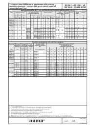
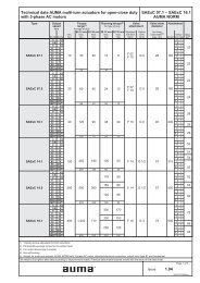
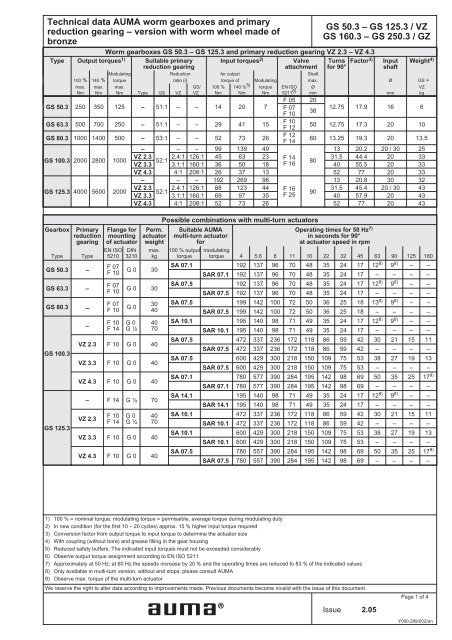
Technical data AUMA worm <strong>gearboxes</strong> <strong>and</strong> primary<br />
reduction gearing <strong>–</strong> version with worm wheel made of<br />
bronze<br />
<strong>Worm</strong> <strong>gearboxes</strong> <strong>GS</strong> <strong>50.3</strong> <strong>–</strong> <strong>GS</strong> <strong>125.3</strong> <strong>and</strong> primary reduction gearing VZ 2.3 <strong>–</strong> VZ 4.3<br />
Type Output torques1) Suitable primary Input torques<br />
reduction gearing<br />
2) Valve Turns Factor<br />
attachment for 90°<br />
3) Input<br />
shaft<br />
Weight 4)<br />
Modulating Reduction for output Shaft<br />
100 % 140 % torque ratio (i) torque of Modulating max. Ø <strong>GS</strong> +<br />
max.<br />
Nm<br />
max.<br />
Nm<br />
max.<br />
Nm Type <strong>GS</strong> VZ<br />
<strong>GS</strong>/<br />
VZ<br />
100 %<br />
Nm<br />
140 % 5)<br />
Nm<br />
torque<br />
Nm<br />
EN ISO<br />
5211 6)<br />
Ø<br />
mm mm<br />
F 05 20<br />
<strong>GS</strong> <strong>50.3</strong> 250 350 125 <strong>–</strong> 51:1 <strong>–</strong> <strong>–</strong> 14 20 7 F 07<br />
F 10<br />
38<br />
12.75 17.9 16 6<br />
<strong>GS</strong> 63.3 500 700 250 <strong>–</strong> 51:1 <strong>–</strong> <strong>–</strong> 29 41 15<br />
F 10<br />
F 12<br />
50 12.75 17.3 20 10<br />
<strong>GS</strong> 80.3 1000 1400 500 <strong>–</strong> 53:1 <strong>–</strong> <strong>–</strong> 52 73 26<br />
F 12<br />
F 14<br />
60 13.25 19.3 20 13.5<br />
<strong>–</strong><br />
<strong>–</strong> <strong>–</strong> 99 139 49<br />
13 20.2 20 / 30 25<br />
<strong>GS</strong> 100.3 2000 2800 1000<br />
VZ 2.3<br />
VZ 3.3<br />
52:1<br />
2.4:1 126:1<br />
3.1:1 160:1<br />
45<br />
36<br />
63<br />
50<br />
23<br />
18<br />
F 14<br />
F 16<br />
80<br />
31.5<br />
40<br />
44.4<br />
55.5<br />
20<br />
20<br />
33<br />
33<br />
VZ 4.3 4:1 208:1 26 37 13 52 77 20 33<br />
<strong>–</strong><br />
<strong>–</strong> <strong>–</strong> 192 269 96<br />
13 20.8 30 32<br />
<strong>GS</strong> <strong>125.3</strong> 4000 5600 2000<br />
VZ 2.3<br />
VZ 3.3<br />
52:1<br />
2.4:1 126:1<br />
3.1:1 160:1<br />
88<br />
69<br />
123<br />
97<br />
44<br />
35<br />
F 16<br />
F 25<br />
90<br />
31.5<br />
40<br />
45.4<br />
57.9<br />
20 / 30<br />
20<br />
43<br />
43<br />
VZ 4.3 4:1 208:1 52 73 26 52 77 20 43<br />
Gearbox Primary<br />
reduction<br />
gearing<br />
Type Type<br />
<strong>GS</strong> <strong>50.3</strong> <strong>–</strong><br />
<strong>GS</strong> 63.3 <strong>–</strong><br />
<strong>GS</strong> 80.3 <strong>–</strong><br />
<strong>GS</strong> 100.3<br />
<strong>GS</strong> <strong>125.3</strong><br />
<strong>–</strong><br />
Flange for<br />
mounting<br />
of actuator<br />
EN ISO<br />
5210<br />
F 07<br />
F 10<br />
F 07<br />
F 10<br />
F 07<br />
F 10<br />
F 10<br />
F 14<br />
DIN<br />
3210<br />
Perm.<br />
actuator<br />
weight<br />
max.<br />
kg<br />
G 0 30<br />
G 0 30<br />
G 0<br />
G 0<br />
G ½<br />
30<br />
40<br />
40<br />
70<br />
VZ 2.3 F 10 G 0 40<br />
VZ 3.3 F 10 G 0 40<br />
VZ 4.3 F 10 G 0 40<br />
<strong>–</strong> F 14 G ½ 70<br />
VZ 2.3<br />
F 10<br />
F 14<br />
G 0<br />
G ½<br />
40<br />
70<br />
VZ 3.3 F 10 G 0 40<br />
VZ 4.3 F 10 G 0 40<br />
Possible combinations with multi-turn actuators<br />
Suitable AUMA<br />
multi-turn actuator<br />
for<br />
100 % output<br />
torque<br />
Operating times for 50 Hz 7)<br />
in seconds for 90°<br />
at actuator speed in rpm<br />
modulating<br />
torque 4 5.6 8 11 16 22 32 45 63 90 125 180<br />
SA 07.1 192 137 96 70 48 35 24 17 12 8) 9 8) <strong>–</strong> <strong>–</strong><br />
SAR 07.1 192 137 96 70 48 35 24 17 <strong>–</strong> <strong>–</strong> <strong>–</strong> <strong>–</strong><br />
SA 07.5 192 137 96 70 48 35 24 17 12 8) 9 8) <strong>–</strong> <strong>–</strong><br />
SAR 07.5 192 137 96 70 48 35 24 17 <strong>–</strong> <strong>–</strong> <strong>–</strong> <strong>–</strong><br />
SA 07.5 199 142 100 72 50 36 25 18 13 8) 9 8) <strong>–</strong> <strong>–</strong><br />
SAR 07.5 199 142 100 72 50 36 25 18 <strong>–</strong> <strong>–</strong> <strong>–</strong> <strong>–</strong><br />
SA 10.1 195 140 98 71 49 35 24 17 12 8) 9 8) <strong>–</strong> <strong>–</strong><br />
SAR 10.1 195 140 98 71 49 35 24 17 <strong>–</strong> <strong>–</strong> <strong>–</strong> <strong>–</strong><br />
SA 07.5 472 337 236 172 118 86 59 42 30 21 15 11<br />
SAR 07.5 472 337 236 172 118 86 59 42 <strong>–</strong> <strong>–</strong> <strong>–</strong> <strong>–</strong><br />
SA 07.5 600 429 300 218 150 109 75 53 38 27 19 13<br />
SAR 07.5 600 429 300 218 150 109 75 53 <strong>–</strong> <strong>–</strong> <strong>–</strong> <strong>–</strong><br />
SA 07.1 780 577 390 284 195 142 98 69 50 35 25 179) SAR 07.1 780 577 390 284 195 142 98 69 <strong>–</strong> <strong>–</strong> <strong>–</strong> <strong>–</strong><br />
SA 14.1 195 140 98 71 49 35 24 17 12 8) 9 8) <strong>–</strong> <strong>–</strong><br />
SAR 14.1 195 140 98 71 49 35 24 17 <strong>–</strong> <strong>–</strong> <strong>–</strong> <strong>–</strong><br />
SA 10.1 472 337 236 172 118 86 59 42 30 21 15 11<br />
SAR 10.1 472 337 236 172 118 86 59 42 <strong>–</strong> <strong>–</strong> <strong>–</strong> <strong>–</strong><br />
SA 10.1 600 429 300 218 150 109 75 53 38 27 19 13<br />
SAR 10.1 600 429 300 218 150 109 75 53 <strong>–</strong> <strong>–</strong> <strong>–</strong> <strong>–</strong><br />
SA 07.5 780 557 390 284 195 142 98 69 50 35 25 179) SAR 07.5 780 557 390 284 195 142 98 69 <strong>–</strong> <strong>–</strong> <strong>–</strong> <strong>–</strong><br />
1) 100 % = nominal torque; modulating torque = permissible, average torque during modulating duty<br />
2) In new condition (for the first 10 <strong>–</strong> 20 cycles) approx. 15 % higher input torque required<br />
3) Conversion factor from output torque to input torque to determine the actuator size<br />
4) With coupling (without bore) <strong>and</strong> grease filling in the gear housing<br />
5) Reduced safety buffers. The indicated input torques must not be exceeded considerably<br />
6) Observe output torque assignment according to EN ISO 5211<br />
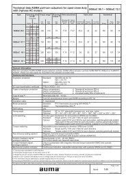
7) Approximately at 50 Hz; at 60 Hz the speeds increase by 20 % <strong>and</strong> the operating times are reduced to 83 % of the indicated values<br />
8) Only available in multi-turn version, without end stops; please consult AUMA<br />
9) Observe max. torque of the multi-turn actuator<br />
We reserve the right to alter data according to improvements made. Previous documents become invalid with the issue of this document.<br />
®<br />
<strong>GS</strong> <strong>50.3</strong> <strong>–</strong> <strong>GS</strong> <strong>125.3</strong> / VZ<br />
<strong>GS</strong> <strong>160.3</strong> <strong>–</strong> <strong>GS</strong> 2<strong>50.3</strong> / GZ<br />
Issue 2.05<br />
VZ<br />
kg<br />
Page1of4<br />
Y000.289/002/en
<strong>GS</strong> <strong>50.3</strong> <strong>–</strong> <strong>GS</strong> <strong>125.3</strong> / VZ<br />
<strong>GS</strong> <strong>160.3</strong> <strong>–</strong> <strong>GS</strong> 2<strong>50.3</strong> / GZ<br />
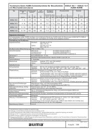
<strong>Worm</strong> <strong>gearboxes</strong> <strong>GS</strong> <strong>160.3</strong> <strong>–</strong> <strong>GS</strong> 2<strong>50.3</strong> <strong>and</strong> primary reduction gearing GZ <strong>160.3</strong> <strong>–</strong> GZ 2<strong>50.3</strong><br />
Type Output torques1) Suitable primary Input torques<br />
reduction gearing<br />
2) Valve Turns Factor<br />
attachment for 90°<br />
3) Input<br />
shaft<br />
1) 100 % = nominal torque; modulating torque = permissible, average torque during modulating duty<br />
2) In new condition (for the first 10 <strong>–</strong> 20 cycles) approx. 15 % higher input torque required<br />
3) Conversion factor from output torque to input torque to determine the actuator size<br />
4) With coupling (pilot bore) <strong>and</strong> grease filling in the gear housing<br />
5) Reduced safety buffers. The indicated input torques must not be exceeded considerably<br />
6) Observe output torque assignment according to EN ISO 5211<br />
7) Approximately at 50 Hz; at 60 Hz the speeds increase by 20 % <strong>and</strong> the operating times are reduced to 83 % of the indicated values<br />
8) Only available in multi-turn version, without end stops; please consult AUMA<br />
9) Observe max. torque of the multi-turn actuator<br />
We We reserve reserve the the right right to to alter alter data data according according to to improvements improvements made. made. Previous documents become invalid with the issue of this document.<br />
Weight 4)<br />
Modulating Reduction for output Shaft<br />
100 % 140 % torque ratio (i) torque of Modulating max. Ø <strong>GS</strong> +<br />
max.<br />
Nm<br />
max.<br />
Nm<br />
max.<br />
Nm Type <strong>GS</strong> GZ<br />
<strong>GS</strong>/<br />
GZ<br />
100 %<br />
Nm<br />
140 % 5)<br />
Nm<br />
torque<br />
Nm<br />
EN ISO<br />
5211 6)<br />
F 25<br />
F 30<br />
Ø<br />
mm mm<br />
<strong>–</strong> 54:1 <strong>–</strong> <strong>–</strong> 353 496 177<br />
100 13.5 22.7 30 80<br />
<strong>GS</strong> <strong>160.3</strong> 8000 11250 4000<br />
GZ <strong>160.3</strong> 54:1 4:1 218:1 97 136 49 54:1 8:1 442:1 48 68 24<br />
F 25<br />
F 30<br />
100<br />
100<br />
54.5<br />
110.5<br />
83<br />
167<br />
20 / 30<br />
20<br />
91<br />
91<br />
<strong>–</strong> 53:1 <strong>–</strong> <strong>–</strong> 718 1009 359<br />
F 30<br />
F 35<br />
125 13.25 22.3 40 140<br />
<strong>GS</strong> 200.3 16000 22500 8000<br />
GZ 200.3<br />
53:1 4:1 214:1<br />
53:1 8:1 434:1<br />
53:1 16:1 864:1<br />
197<br />
97<br />
52<br />
277<br />
137<br />
73<br />
99<br />
49<br />
26<br />
F 30<br />
F 35<br />
125<br />
125<br />
125<br />
53.5<br />
108.5<br />
216,25<br />
81.3<br />
165<br />
308<br />
30<br />
20 / 30<br />
20<br />
160<br />
160<br />
170<br />
<strong>–</strong> 52:1 <strong>–</strong> <strong>–</strong> 1462 2060 732<br />
F 35<br />
F 40<br />
160 13 21.9 50 273<br />
<strong>GS</strong> 2<strong>50.3</strong> 32000 45000 16000<br />
GZ 2<strong>50.3</strong><br />
52:1 4:1 210:1<br />
52:1 8:1 411:1<br />
52:1 16:1 848:1<br />
401<br />
205<br />
105<br />
563<br />
289<br />
148<br />
200<br />
103<br />
53<br />
F 35<br />
F 40<br />
160<br />
160<br />
160<br />
52,5<br />
103<br />
212<br />
80<br />
156<br />
305<br />
30 / 40<br />
30<br />
20 / 30<br />
296<br />
296<br />
308<br />
Gearbox Primary<br />
reduction<br />
gearing<br />
Type Type i<br />
<strong>GS</strong> <strong>160.3</strong><br />
<strong>GS</strong> 200.3<br />
<strong>GS</strong> 2<strong>50.3</strong><br />
<strong>–</strong> <strong>–</strong><br />
GZ <strong>160.3</strong><br />
4:1<br />
<strong>–</strong> <strong>–</strong><br />
GZ 200.3<br />
<strong>–</strong><br />
GZ 2<strong>50.3</strong><br />
Flange for<br />
mounting<br />
of actuator<br />
EN ISO<br />
5210<br />
F 14<br />
F 16<br />
F 10<br />
F 14<br />
DIN<br />
3210<br />
G ½<br />
G 3<br />
G 0<br />
G ½<br />
Possible combinations with multi-turn actuators<br />
Perm.<br />
actuator<br />
weight<br />
max.<br />
kg<br />
100<br />
70<br />
8:1 F10 G 0 40<br />
F 16<br />
F 25<br />
G 3 290<br />
4:1 F 14 G ½ 70<br />
8:1<br />
F 10<br />
F 14<br />
G 0<br />
G ½<br />
70<br />
16:1 F 10 G 0 40<br />
<strong>–</strong><br />
F 25<br />
F 30<br />
<strong>–</strong> 340<br />
4:1 F 14 G ½ 100<br />
8:1 F 14 G ½ 70<br />
16:1<br />
Issue 2.05<br />
F 10<br />
F 14<br />
G 0<br />
G ½<br />
Page2of4<br />
Y000.289/002/en<br />
70<br />
Technical data AUMA worm <strong>gearboxes</strong> <strong>and</strong> primary<br />
reduction gearing <strong>–</strong> version with worm wheel made of<br />
bronze<br />
Suitable AUMA<br />
multi-turn actuator<br />
for<br />
100 %<br />
output<br />
torque<br />
Operating times for 50 Hz 7)<br />
in seconds for 90°<br />
at actuator speed in rpm<br />
modulating<br />
torque 4 5.6 8 11 16 22 32 45 63 90 125 180<br />
SA 14.5 203 145 102 74 51 37 25 18 13 8) 9 8) <strong>–</strong> <strong>–</strong><br />
SAR 14.5 203 145 102 74 51 37 25 18 <strong>–</strong> <strong>–</strong> <strong>–</strong> <strong>–</strong><br />
SA 10.1 818 584 409 297 204 149 102 73 52 36 26 189) SAR 10.1 818 584 409 297 204 149 102 73 <strong>–</strong> <strong>–</strong> <strong>–</strong> <strong>–</strong><br />
SA 07.5 <strong>–</strong> <strong>–</strong> 829 603 414 301 207 147 105 74 53 379) SAR 07.5 <strong>–</strong> <strong>–</strong> 829 603 414 301 207 147 <strong>–</strong> <strong>–</strong> <strong>–</strong> <strong>–</strong><br />
SA 16.1 199 142 100 72 50 36 25 18 13 8) 9 8) <strong>–</strong> <strong>–</strong><br />
SAR 16.1 199 142 100 72 50 36 25 18 <strong>–</strong> <strong>–</strong> <strong>–</strong> <strong>–</strong><br />
SA 14.1 803 573 401 292 201 146 100 71 51 36 26 189) SAR 14.1 803 573 401 292 201 146 100 71 <strong>–</strong> <strong>–</strong> <strong>–</strong> <strong>–</strong><br />
SA 10.1 <strong>–</strong> <strong>–</strong> 814 592 407 296 203 145 103 72 52 369) SAR 10.1 <strong>–</strong> <strong>–</strong> 814 592 407 296 203 145 <strong>–</strong> <strong>–</strong> <strong>–</strong> <strong>–</strong><br />
SA 07.5 <strong>–</strong> <strong>–</strong> <strong>–</strong> <strong>–</strong> 810 589 405 288 206 144 104 729) SAR 07.5 <strong>–</strong> <strong>–</strong> <strong>–</strong> <strong>–</strong> 810 589 405 288 <strong>–</strong> <strong>–</strong> <strong>–</strong> <strong>–</strong><br />
SA 25.1 195 140 98 71 49 35 24 17 8) 12 8) <strong>–</strong> <strong>–</strong> <strong>–</strong><br />
SAR 25.1 195 140 98 71 <strong>–</strong> <strong>–</strong> <strong>–</strong> <strong>–</strong> <strong>–</strong> <strong>–</strong> <strong>–</strong> <strong>–</strong><br />
SA 14.5 788 563 394 286 197 143 98 70 50 35 25 189) SAR 14.5 788 563 394 286 197 143 98 70 <strong>–</strong> <strong>–</strong> <strong>–</strong> <strong>–</strong><br />
SA 14.1 <strong>–</strong> <strong>–</strong> 773 562 386 281 193 137 98 69 49 349) SAR 14.1 <strong>–</strong> <strong>–</strong> 773 562 386 281 193 137 <strong>–</strong> <strong>–</strong> <strong>–</strong> <strong>–</strong><br />
SA 10.1 <strong>–</strong> <strong>–</strong> <strong>–</strong> <strong>–</strong> 795 578 398 283 202 141 102 719) SAR 10.1 <strong>–</strong> <strong>–</strong> <strong>–</strong> <strong>–</strong> 795 578 398 283 <strong>–</strong> <strong>–</strong> <strong>–</strong> <strong>–</strong><br />
®<br />
GZ<br />
kg
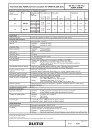
Technical data AUMA worm <strong>gearboxes</strong> <strong>and</strong> primary<br />
reduction gearing <strong>–</strong> version with worm wheel made of<br />
bronze<br />
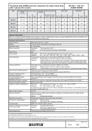
Application<br />
For motor <strong>and</strong> manual operation of valves (e.g. butterfly <strong>and</strong> ball valves), especially suitable for modulating duty.<br />
For special applications, e.g. dampers or gas diverters, special sizing is required.<br />
Features <strong>and</strong> functions<br />
Type of duty Short-time duty S2 - 15 min. (open-close duty)<br />
Intermittent duty S4 - 25 % (modulating duty)<br />
Version St<strong>and</strong>ard: clockwise rotation RR, counterclockwise rotation LL, option: RL or LR<br />
Self-locking The <strong>gearboxes</strong> are self-locking when at st<strong>and</strong>-still under normal service conditions; strong<br />
vibrations may cancel the self-locking effect. While in motion, safe breaking is not<br />
guaranteed. If this is required, a separate brake must be used.<br />
End stops Positive for both end positions by travelling nut, sensitive adjustmen<br />
Strength of end stop Guaranteed strength of end stop (in Nm) for input side operation according to AWWA<br />
Swing angle<br />
<strong>GS</strong> <strong>50.3</strong> <strong>–</strong> <strong>GS</strong> <strong>125.3</strong><br />
Swing angle<br />
<strong>GS</strong> <strong>160.3</strong> <strong>–</strong> <strong>GS</strong> 2<strong>50.3</strong><br />
St<strong>and</strong>ard: Fixed swing angle up to max. 100°; set in the factory to 92° unless ordered otherwise.<br />
Options: adjustable in steps of:<br />
10°<strong>–</strong> 35°, 35° <strong>–</strong> 60°, 60° <strong>–</strong> 80°, 80° <strong>–</strong> 100°,<br />
100° <strong>–</strong> 125°, 125° <strong>–</strong> 150°, 150° <strong>–</strong> 170°, 170° <strong>–</strong> 190°<br />
Swing angle > 190°, multi-turn version without end stops, version <strong>GS</strong>D<br />
St<strong>and</strong>ard: adjustable 80° <strong>–</strong> 100°; set in the factory to 92° unless ordered otherwise.<br />
Options: adjustable in steps of: 20° <strong>–</strong> 40°, 40° <strong>–</strong> 60°, 60° <strong>–</strong> 80°,<br />
Swing angle > 100°, multi-turn version without end stops, version <strong>GS</strong>D<br />
Mechanical position indicator St<strong>and</strong>ard: Pointer cover for continuous position indication<br />
Options: Sealed pointer cover for horizontal outdoor installation 10)<br />
Protection cover for buried service instead of pointer cover<br />
Input shaft Cylindrical with parallel key according to DIN 6885.1 (refer to tables page 1 <strong>and</strong> page 2)<br />
Operation<br />
Motor operation With electric multi-turn actuator, directly or through primary reduction gearing VZ/ GZ<br />
Flanges for mounting of actuator, refer to tables page 1 <strong>and</strong> page 2.<br />
Manual operation Via h<strong>and</strong>wheel, directly or through primary reduction gearing VZ/ GZ<br />
Available h<strong>and</strong>wheel diameters, selection according to the max. output torque:<br />
Primary reduction gearing<br />
Primary reduction gearing<br />
Valve attachment<br />
Planetary gear with various reduction ratios for reducing the input torques (see tables pages 1 <strong>and</strong> 2)<br />
Valve attachment Dimensions according to EN ISO 5211 (refer to tables page 1 <strong>and</strong> page 2):<br />
St<strong>and</strong>ard: <strong>GS</strong> <strong>50.3</strong> <strong>–</strong> <strong>GS</strong> <strong>125.3</strong>: without spigot<br />
<strong>GS</strong> <strong>160.3</strong> <strong>–</strong> <strong>GS</strong> 2<strong>50.3</strong>: with spigot<br />
Options: <strong>GS</strong> <strong>50.3</strong> <strong>–</strong> <strong>GS</strong> <strong>125.3</strong>: with spigot<br />
<strong>GS</strong> <strong>160.3</strong> <strong>–</strong> <strong>GS</strong> 2<strong>50.3</strong>: without spigot<br />
Splined coupling for connection<br />
to the valve shaft<br />
Service conditions<br />
<strong>GS</strong> <strong>50.3</strong> <strong>–</strong> <strong>GS</strong> <strong>125.3</strong> / VZ<br />
<strong>GS</strong> <strong>160.3</strong> <strong>–</strong> <strong>GS</strong> 2<strong>50.3</strong> / GZ<br />
Type<br />
Primary red.<br />
<strong>GS</strong> <strong>50.3</strong> <strong>GS</strong> 63.3 <strong>GS</strong> 80.3 <strong>GS</strong> 100.3 <strong>GS</strong> <strong>125.3</strong><br />
gearing <strong>–</strong> <strong>–</strong> <strong>–</strong> VZ 2.3 VZ 3.3 VZ 4.3 VZ 2.3 VZ 3.3 VZ 4.3<br />
Nm 250 450 450 500 250 500 250<br />
Type<br />
Primary red.<br />
<strong>GS</strong> <strong>160.3</strong> <strong>GS</strong> 200.3 <strong>GS</strong> 2<strong>50.3</strong><br />
gearing GZ <strong>160.3</strong> GZ 200.3 GZ 2<strong>50.3</strong><br />
Reduction ratio 4:1 8:1 4:1 8:1 16:1 4:1 8:1 16:1<br />
Nm 500 450 500 500<br />
Type<br />
Primary red.<br />
<strong>GS</strong> <strong>50.3</strong> <strong>GS</strong> 63.3 <strong>GS</strong> 80.3 <strong>GS</strong> 100.3 <strong>GS</strong> <strong>125.3</strong><br />
gearing <strong>–</strong> <strong>–</strong> <strong>–</strong> <strong>–</strong> VZ 2.3 VZ 3.3 VZ 4.3 <strong>–</strong> VZ 2.3 VZ 3.3 VZ 4.3<br />
H<strong>and</strong>wheel Ø<br />
mm<br />
160<br />
200<br />
250<br />
St<strong>and</strong>ard: Without bore or pilot bore from <strong>GS</strong> <strong>160.3</strong><br />
<strong>Worm</strong> gearbox can be repositioned 4 x 90° on coupling<br />
Options: Machined with bore <strong>and</strong> keyway, square bore or bore with two-flats<br />
10) For gas applications with sealed pointer cover, an air vent in the pointer cover or venting grooves in the valve mounting flange must be provided<br />
We reserve the right to alter data according to improvements made. Previous documents become invalid with the issue of this document.<br />
®<br />
250<br />
315<br />
315<br />
400<br />
400<br />
500<br />
Type<br />
Primary red.<br />
<strong>GS</strong> <strong>160.3</strong> <strong>GS</strong> 200.3 <strong>GS</strong> 2<strong>50.3</strong><br />
gearing <strong>–</strong> GZ <strong>160.3</strong> <strong>–</strong> GZ 200.3 <strong>–</strong> GZ 2<strong>50.3</strong><br />
H<strong>and</strong>wheel Ø<br />
mm<br />
630<br />
800<br />
315<br />
400<br />
400 315 <strong>–</strong> 500<br />
630<br />
315<br />
400<br />
250<br />
315<br />
500<br />
630<br />
800<br />
Issue 2.05<br />
400<br />
500<br />
400<br />
500<br />
400 315 <strong>–</strong> 800 500<br />
630<br />
315<br />
400<br />
400<br />
Page3of4<br />
Y000.289/002/en
<strong>GS</strong> <strong>50.3</strong> <strong>–</strong> <strong>GS</strong> <strong>125.3</strong> / VZ<br />
<strong>GS</strong> <strong>160.3</strong> <strong>–</strong> <strong>GS</strong> 2<strong>50.3</strong> / GZ<br />
Enclosure protection according<br />
to EN 60 529 11)<br />
St<strong>and</strong>ard: IP 68-3, dust <strong>and</strong> water tight up to max. 3 m head of water<br />
Options 12) : IP 68-6, dust <strong>and</strong> water tight up to max. 6 m head of water<br />
IP 68-10, dust <strong>and</strong> water tight up to max. 10 m head of water<br />
IP 68-20, dust <strong>and</strong> water tight up to max. 20 m head of water<br />
Corrosion protection St<strong>and</strong>ard: KN Suitable for installation in industrial units,<br />
in water or power plants with a low pollutant concentration<br />
Options: KS Suitable for installation in occasionally or permanently aggressive<br />
atmosphere with a moderate pollutant concentration<br />
(e.g. in wastewater treatment plants, chemical industry)<br />
KX Suitable for installation in extremely aggressive atmosphere with high<br />
humidity <strong>and</strong> high pollutant concentration<br />
Paint St<strong>and</strong>ard: <strong>GS</strong> <strong>50.3</strong> <strong>–</strong> <strong>GS</strong> <strong>125.3</strong>: Two-component iron-mica combination<br />
<strong>GS</strong> <strong>160.3</strong> <strong>–</strong> <strong>GS</strong> 2<strong>50.3</strong>: Primer coating<br />
Option: <strong>GS</strong> <strong>160.3</strong> <strong>–</strong> <strong>GS</strong> 2<strong>50.3</strong>: Two-component iron-mica combination<br />
Colour St<strong>and</strong>ard: silver-grey (DB 701, similar to RAL 9007)<br />
Option: Other colours on request<br />
Ambient temperature St<strong>and</strong>ard: <strong>–</strong> 25 °C to + 80 °C<br />
Options: <strong>–</strong> 40 °C to + 60 °C (low temperature), version L<br />
<strong>–</strong> 60 °C to + 60 °C (extreme low temperature), version EL<br />
<strong>–</strong> 0 °C to + 120 °C (high temperature), version H<br />
Lifetime The lifetime is based on a load typical for part-turn valves<br />
Type Operation cycles (OPEN-CLOSE-OPEN)<br />
for swivel movements of 90° (max. 100°)<br />
<strong>and</strong> a maximum output torque of<br />
100 % 140 %<br />
<strong>GS</strong> <strong>50.3</strong> 15,000 5,000<br />
<strong>GS</strong> 63.3 15,000 5,000<br />
<strong>GS</strong> 80.3 15,000 5,000<br />
<strong>GS</strong> 100.3 15,000 5,000<br />
<strong>GS</strong> <strong>125.3</strong> 15,000 5,000<br />
<strong>GS</strong> <strong>160.3</strong> 15,000 5,000<br />
<strong>GS</strong> 200.3 15,000 5,000<br />
<strong>GS</strong> 2<strong>50.3</strong> 10,000 3,000<br />
Accessories<br />
Valve position indicators Position indicator WSG for the signalisation of intermediate <strong>and</strong> end positions for precise<br />
<strong>and</strong> low-backlash feedback for swing angles ranging from 82° <strong>–</strong> 98°<br />
(refer to separate data sheet)<br />
Valve position indicator WGD for signalisation of intermediate <strong>and</strong> end positions for swing<br />
angles > 180° (refer to separate data sheet)<br />
Limit switching Limit switching WSH for manually operated valves. For the signalisation of intermediate <strong>and</strong><br />
end positions (refer to separate data sheet)<br />
Special features for use in potentially explosive atmospheres<br />
Explosion protection II2G c IIC T4 according to ATEX 94/9/EC<br />
Type of duty Short-time duty S2 - 15 min., max. 3 cycles (OPEN<strong>–</strong>CLOSE<strong>–</strong>OPEN) 90°, then cool-down to<br />
ambient temperature<br />
Intermittent duty S4 - 25 % up to the maximum modulating torque<br />
Swing angle Swing angle > 90° on request<br />
Ambient temperature St<strong>and</strong>ard: <strong>–</strong> 20 °C to + 40 °C<br />
Options: <strong>–</strong> 40 °C to + 40 °C (low temperature)<br />
<strong>–</strong> 20 °C to + 60 °C<br />
<strong>–</strong> 40 °C to + 60 °C (low temperature)<br />
<strong>–</strong> 50 °C to + 60 °C (extreme low temperature)<br />
<strong>–</strong> 60 °C to + 60 °C (extreme low temperature)<br />
Combinations with actuators SA (R)ExC at ambient temperatures > 40 °C with special sizing<br />
Other information<br />
Reference documents Brochure worm <strong>gearboxes</strong> <strong>GS</strong> <strong>50.3</strong> <strong>–</strong> <strong>GS</strong> 2<strong>50.3</strong> / <strong>GS</strong> 315 <strong>–</strong> <strong>GS</strong> 500<br />
Dimension sheets <strong>GS</strong> <strong>50.3</strong> <strong>–</strong> <strong>GS</strong> <strong>125.3</strong>, <strong>GS</strong> <strong>160.3</strong> <strong>–</strong> <strong>GS</strong> 2<strong>50.3</strong><br />
Technical data SA, SAR, WSG, WGD, WSH<br />
Lever <strong>gearboxes</strong> See separate documents<br />
11) Refer to information sheet “Enclosure protection IP 68 (submersible) for worm <strong>gearboxes</strong> <strong>and</strong> primary reduction gearings”<br />
12) Not available for <strong>GS</strong> <strong>50.3</strong><br />
Y000.289/002/en<br />
Technical data AUMA worm <strong>gearboxes</strong> <strong>and</strong> primary<br />
reduction gearing <strong>–</strong> version with worm wheel made of<br />
bronze<br />
We We reserve reserve the the right right to to alter alter data data according according to to improvements improvements made. made. Previous documents become invalid with the issue of this document.<br />
Issue 2.05<br />
Page4of4<br />
®