General instructions for installation, use and maintenance of ... - fagor
General instructions for installation, use and maintenance of ... - fagor
General instructions for installation, use and maintenance of ... - fagor

You also want an ePaper? Increase the reach of your titles
YUMPU automatically turns print PDFs into web optimized ePapers that Google loves.
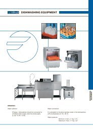
<strong>General</strong> <strong>instructions</strong> <strong>for</strong> <strong>installation</strong>, <strong>use</strong> <strong>and</strong><br />
<strong>maintenance</strong> <strong>of</strong> STATIC OVENS
Dear costumer<br />
We would like to thank you <strong>for</strong> the confidence you have shown in our product on purchasing a pr<strong>of</strong>essional<br />
appliance. We are totally convinced that in time you will be completely satisfied with your purchase.<br />
Take a few minutes <strong>of</strong> your time <strong>and</strong> get to know the appliance with this <strong>instructions</strong> manual <strong>and</strong> "down to<br />
work": the easy to underst<strong>and</strong> graphical in<strong>for</strong>mation replaces pages full <strong>of</strong> writing.<br />
Nevertheless, we recommend you thoroughly read this manual compiled by FAGOR's kitchen supervisors,<br />
in order to benefit to the maximum from the multiple possibilities <strong>and</strong> advantages this appliance <strong>of</strong>fers you.<br />
Keep this manual near to the appliance <strong>and</strong> at all times in an accessible place.<br />
Lastly, we wish you success <strong>and</strong> hope that you will be fully satisfied with your new bain-marie.<br />
Idex<br />
Installation<br />
Use<br />
Maintenance<br />
Environmental protection recommendation<br />
<strong>General</strong> <strong>and</strong> connection dimensions 1<br />
Positioning <strong>and</strong> levelling 21<br />
Electrical connection 21<br />
Technical specifications 20<br />
Turning the appliance on 22<br />
Turning the oven <strong>of</strong>f 3<br />
Maintenance 22<br />
Environmental protection recommendation 22-23
OUTER<br />
DIMENSIONS<br />
OVEN<br />
DIMENSIONS<br />
Table <strong>of</strong> specifications (no 1)<br />
MODEL HG9-10 HG9-20<br />
Width 850 850<br />
(mm) Depth 890 890<br />
(mm)<br />
Height 680 1315<br />
Width 540 540<br />
Depth 660 660<br />
Height 305 305<br />
NET WEIGHT (Kgs.) 65 130<br />
NUMBER OF<br />
BURNERS<br />
NOMINAL CONSUMPTION<br />
TOTAL<br />
POWER<br />
8000 (hob) 1 2<br />
m /h<br />
Kg/h<br />
G-110 2.22 4.44<br />
G-130 1.01 2.02<br />
G-150 1.72 3.44<br />
G-20 0.91 1.82<br />
G-25 1.06 2.12<br />
G-30 0.68 1.36<br />
G-31 0.67 1.34<br />
(Lower calorific power) kw/h 8.6 17.02<br />
(Higher calorific power)<br />
kcal/h 8.2 16.4<br />
CONSUMPTION OF AIR<br />
Mod. Consumption <strong>of</strong> necessary air <strong>for</strong> the combustion<br />
Nm³/h<br />
HG9-10 10<br />
HG9-20 20<br />
OVEN SETTING AND TEMPERATURE (APPROXIMATE) TABLE (No 2)<br />
220-280ºC 230-250ºC<br />
250-300ºC 230-250ºC<br />
220-250ºC 210-240ºC<br />
200-220ºC 200-230ºC<br />
220-250ºC 190-210ºC<br />
1<br />
2<br />
3<br />
4<br />
5<br />
6<br />
7<br />
105ºC<br />
155ºC<br />
190ºC<br />
220ºC<br />
265ºC<br />
300ºC<br />
335ºC
COUN<br />
TRIES<br />
TABLE OF CATEGORIES, GASES AND OPERATING PRESSURES (No 3)<br />
1st FAMILY 2nd FAMILY 3rd FAMILY<br />
Group A Group C Group E Group H Group L Group E<br />
Gas<br />
Pressur<br />
e Gas (mbar) Pressure<br />
(mbar)<br />
Ga<br />
s<br />
Pressure<br />
(mbar)<br />
Ga<br />
s<br />
Pressur<br />
e<br />
(mbar)<br />
Ga<br />
s<br />
Pressur<br />
e<br />
(mbar)<br />
Ga<br />
s<br />
Pressur<br />
e<br />
(mbar)<br />
Group<br />
E+<br />
Ga<br />
s<br />
Pressur<br />
e<br />
(mbar)<br />
Grou<br />
p B/P<br />
DK G-110 8 G-20 20 30<br />
BE<br />
G-<br />
20+<br />
G-25<br />
Ga<br />
s<br />
Group 3+<br />
Pressur<br />
e Gas (mbar) Pressur<br />
e<br />
(mbar)<br />
20/25 G-30+<br />
G-31<br />
DE G-20 20 50<br />
ES G-110 8 G-130 8 G-150 8 G-20 18 G-30+<br />
FR G-130 8<br />
G-<br />
20+<br />
G-25<br />
G-31<br />
20/25 G-30+<br />
G-31<br />
IE G-20 20 G-30+<br />
G-31<br />
LU G-<br />
20+<br />
G-25<br />
NL G-25 25<br />
20/25 G-30+<br />
G-31<br />
G-30/<br />
G-31 30<br />
PT G-20 20 G-30+<br />
G-31<br />
GB G-20 20 G-30+<br />
G-31<br />
AT G-20 20 G-30/<br />
G-31 50<br />
FI G-20 20 G-30/<br />
G-31 30<br />
GR G-20 20 G-30+<br />
G-31<br />
IT G-110 8 G-20 20 G-30+<br />
G-31<br />
SE G-110 8 G-20 20 G-30/<br />
G-31 30<br />
CH G-110 8 G-20 20 G-30+<br />
G-31<br />
NR G-110 8 G-20 20 G-30/<br />
G-31 30<br />
DIFFERENT REFERENCE GAS TABLE (No 4)<br />
28/3<br />
7<br />
28/3<br />
7<br />
28/3<br />
7<br />
28/3<br />
7<br />
28/3<br />
7<br />
30/3<br />
7<br />
28/3<br />
7<br />
28/3<br />
7<br />
30/3<br />
7<br />
30/3<br />
7<br />
Kcal/m3 Kcal/kg<br />
CITY GAS NATURAL GAS LP GAS<br />
G-110 G-130 G-150 G-20 G-25 G-30 G-31<br />
LOWER CALORIFIC POWER 3,515 5,960 4,542 8,573 7,372 10,901 11,066<br />
1a<br />
2a<br />
3a<br />
INJECTOR DIAMETER AND ADJUSTMENT TABLE (No 5)<br />
FAMILY/GAS<br />
Lower<br />
heating power Injector<br />
(mm)<br />
G-110 3,515<br />
G-130 5,960<br />
G-150 Kcl/m3 4,532<br />
G-20 8,573<br />
G-<br />
G-25<br />
7,372<br />
30<br />
28 mbar<br />
50 mbar<br />
Kcl/Kg.<br />
10,901<br />
1.45<br />
1.20<br />
37 mbar<br />
11,066 1.45<br />
G-<br />
31<br />
OVEN BURNER OVEN PILOT LIGHTS<br />
H<br />
(mm)<br />
Injector<br />
(mm)<br />
H<br />
(mm)<br />
4.23 20 ADJUSTABLE -<br />
2.25 20 0.40 -<br />
30 0.25 -
1.1 POSITIONING<br />
1.- INSTALLATION<br />
Positioning <strong>and</strong> electrical <strong>installation</strong> must be always carried out by an AUTHORISED TECHNICIAN,<br />
in compliance with the st<strong>and</strong>ards <strong>of</strong> each country.<br />
a) It is essential to install an extractor hood <strong>for</strong> correct functioning.<br />
b) Install the appliance in well-ventilated premises.<br />
c) Level <strong>and</strong> adjust the height <strong>of</strong> the appliance (Fig. 1).<br />
1.2 GAS CONNECTION<br />
It is essential to have a mains tap <strong>and</strong> a pressure regulator to carry out the gas connection properly,<br />
<strong>and</strong> it is also advisable to <strong>use</strong> a blocking key <strong>for</strong> each appliance.<br />
For LP, natural gas, or city gas, the appliance mains supply should be per<strong>for</strong>med as shown in (Fig. 3-<br />
Fig. 3 bis).<br />
The gas intake <strong>and</strong> its location on the appliance are shown by the letter "G".<br />
1.3. CONVERSION FOR DIFFERENT TYPES OF GAS.<br />
If the appliance is set up <strong>for</strong> a type <strong>of</strong> gas different to that available in your <strong>installation</strong>,<br />
proceed as follows:<br />
Stop gas permeation system into the appliance, if connected. (Any conversion work on the<br />
appliance's<br />
Should always be carried out by an AUTHORISED SERVICE ENGINEER).<br />
CONVERTING HOB AND OVEN BURNERS.<br />
a) Remove the door <strong>of</strong> the oven (The position <strong>of</strong> the injector is shown letter I, behind the door, left<br />
lower part.<br />
b) Replace the injectors "I" (Fig. 5), depending on the gas to be <strong>use</strong>d (table 5).<br />
c) Burner air adjustement.<br />
Place the Venturi "V" (Fig. 5) to the "H" setting, as shown table 5 <strong>and</strong> depending on the gas to be<br />
<strong>use</strong>d.<br />
CONVERTING THE PILOT LIGHTS<br />
a) Remove the plug "A" (Fig.2).<br />
b) For LPG. <strong>and</strong> NATURAL GAS replace the injector "B" tightening it fully. For TOWN GAS, turn in one<br />
direction or another until a stable flame is achieved (Fig. 2)<br />
c) Turn the air regulator "C" until the flame stabilizes (Fig. 2).
2.1 OVEN CONTROL PANEL<br />
TURNING THE OVEN ON<br />
2.- USE<br />
a) Using the plate lifting lever, lift <strong>of</strong>f the first oven plate.<br />
b) Press the "MTH" button (Fig. 4) <strong>and</strong>, at the same tame, turn it to the "2" pilot light position (Fig.<br />
4), <strong>and</strong> press the piezoelectric ignition "P" (Fig. 4) several times until the pilot light stabilizes.<br />
c) From now on, to light the burner, turn by pressing the thermostat control "MTH" (Fig 4)<br />
anticlockwise, to the setting <strong>for</strong> the temperature required (see Table No 2).<br />
TURNING THE OVEN OFF<br />
a) Turn the thermostat control (Fig. 4) clockwise to the pilot setting "2". The burner will go out <strong>and</strong><br />
the pilot light will remain on.<br />
b) To turn <strong>of</strong>f the pilot light, press <strong>and</strong> turn the thermostat control clockwise to the setting "1" (Fig. 4).
3.1 DAILY CLEANING<br />
3-MAINTENANCE<br />
To keep the appliance as good as new, you should observe the following <strong>instructions</strong>:<br />
a) Do not <strong>use</strong> powder or abrasive detergents.<br />
b) Do not <strong>use</strong> a water hose <strong>for</strong> cleaning the appliance.<br />
c) The inside surfaces <strong>of</strong> the ovens should be cleaned everyday after <strong>use</strong>. Use one <strong>of</strong> special<br />
grease-removing products available on the market.<br />
3.2 INDICATIONS ON HOW TO USE THE OVEN<br />
a) Be<strong>for</strong>e using the oven, it is recommended that the inside be cleaned with a damp, soapy cloth, to<br />
prevent bad smells the first time it is <strong>use</strong>d.<br />
b) Several trays <strong>of</strong> food can be cooked at the same time, with good results in all <strong>of</strong> them, thanks to<br />
the heating system <strong>use</strong>d.<br />
3.3 FUNCTIONAL COMPONENTS<br />
1.-Oven thermostatic tap-valve "TH".<br />
2.- Oven pilot light "P.<br />
3.- Hob thermocouple "T.<br />
IMPORTANT NOTE:<br />
The replacement <strong>of</strong> any functional component that might affect safety, should be done by an<br />
AUTHORISED SERVICE ENGINEER.<br />
As a general working rule, you must ensure that that the gas main has been turned <strong>of</strong>f <strong>and</strong> that there<br />
are no flames close to the appliance.<br />
This appliance is only <strong>for</strong> pr<strong>of</strong>essional <strong>use</strong> <strong>and</strong><br />
it should be <strong>use</strong>d by qualified personnel