

A Case Study in Integrated Design: Modeling for High-Performance ...
A Case Study in Integrated Design: Modeling for High-Performance ...
A Case Study in Integrated Design: Modeling for High-Performance ...

Create successful ePaper yourself
Turn your PDF publications into a flip-book with our unique Google optimized e-Paper software.
A <strong>Case</strong> <strong>Study</strong> <strong>in</strong> <strong>Integrated</strong> <strong>Design</strong>:<br />
Model<strong>in</strong>g <strong>for</strong> <strong>High</strong>-Per<strong>for</strong>mance Façades<br />
M. Susan Ubbelohde George A. Loisos Santosh V. Philip<br />
ABSTRACT<br />
This paper presents a case study of an 11-story, 267,000 ft 2 (24,804 m 2 ) office build<strong>in</strong>g <strong>for</strong> San Francisco, Cali<strong>for</strong>nia. Integrat<strong>in</strong>g<br />
build<strong>in</strong>g per<strong>for</strong>mance consultants early <strong>in</strong> the design process enabled strategic use of thermal, daylight<strong>in</strong>g, energy use,<br />
and com<strong>for</strong>t model<strong>in</strong>g to produce a susta<strong>in</strong>able build<strong>in</strong>g with a high-per<strong>for</strong>mance exterior envelope. Analytical techniques<br />
<strong>in</strong>cluded site shad<strong>in</strong>g evaluation, physical test cells of advanced daylight<strong>in</strong>g products, and energy model<strong>in</strong>g parametrics dur<strong>in</strong>g<br />
schematic design and design development phases. A method to evaluate the thermal com<strong>for</strong>t per<strong>for</strong>mance of curta<strong>in</strong>wall alternatives<br />
was developed to quantify human com<strong>for</strong>t conditions with<strong>in</strong> the perimeter zone. This method utilizes noncommercial thermal<br />
per<strong>for</strong>mance software, <strong>in</strong>clud<strong>in</strong>g WINDOW and THERM, DOE2.1e and UCBCOMFORT, as well as a newly developed<br />
method of calculat<strong>in</strong>g mean radiant temperature (MRT).<br />
INTRODUCTION<br />
The office build<strong>in</strong>g that <strong>for</strong>ms this case study is located <strong>in</strong><br />
downtown San Francisco, adjacent to a 1977 build<strong>in</strong>g also<br />
occupied by the client. Construction is scheduled to start <strong>in</strong><br />
2004. The new 11-story build<strong>in</strong>g will be a 267,000 ft 2 (24,800<br />
m 2 ) build<strong>in</strong>g and will house 800 employees. The downtown<br />
site is constricted and land values and construction costs <strong>in</strong> San<br />
Francisco are both high. This results <strong>in</strong> a need to maximize<br />
allowable floor area and fill much of the volume of the site.<br />
The street grid south of Market <strong>in</strong> San Francisco is approximately<br />
45 degrees off card<strong>in</strong>al, result<strong>in</strong>g <strong>in</strong> a build<strong>in</strong>g volume<br />
with façades oriented to the northeast, southeast, southwest,<br />
and northwest. The northwest façade faces the earlier, 16-story<br />
build<strong>in</strong>g and is canted back from bottom to top to let light <strong>in</strong>to<br />
a shared plaza between the two build<strong>in</strong>gs. The entrance is on<br />
the southwest through a double-height lobby. The challenge of<br />
design<strong>in</strong>g this build<strong>in</strong>g to act <strong>in</strong> concert with the earlier build<strong>in</strong>g<br />
led the architects to design the southeast and northeast<br />
corners of the exterior wall to refer to the curta<strong>in</strong>wall design<br />
of the 1977 build<strong>in</strong>g (Figure 1).<br />
©2004 ASHRAE.<br />
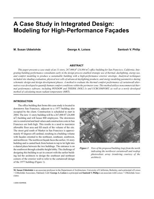
Figure 1 View of the proposed build<strong>in</strong>g (top) from the north<br />
<strong>in</strong>dicat<strong>in</strong>g the northwest curta<strong>in</strong>wall and rooftop<br />
photovoltaic array (render<strong>in</strong>g courtesy of the<br />
architect).<br />
M. Susan Ubbelohde is an associate professor <strong>in</strong> the Department of Architecture, University of Cali<strong>for</strong>nia, Berkeley, and a pr<strong>in</strong>cipal of Loisos<br />
+ Ubbelohde Associates, Oakland, Calif. George A. Loisos is a pr<strong>in</strong>cipal and Santosh V. Philip is an associate with Loisos + Ubbelohde Associates.
(a) (b)<br />
Figure 2 (a) Full build<strong>in</strong>g section cut through NW and SE curta<strong>in</strong>walls. (b) Plan <strong>for</strong> typical office floor.<br />
Site constra<strong>in</strong>ts <strong>for</strong>med a large, rectangular build<strong>in</strong>g plate<br />
with bays that average 140 ft (42.67 m) by 184 ft (56 m) around<br />
a central core. This leaves 63 ft (19.20 m) deep office bays on<br />
the northwest and southeast, with narrower bays of 34 ft (10.36<br />
m) depth on the southwest and northeast. Recogniz<strong>in</strong>g site<br />
height restrictions, the floor-to-floor dimension is 13 ft-9 <strong>in</strong>.<br />
(4.2 m) with a 9 ft-10 <strong>in</strong>. (3.0 m) floor-to-ceil<strong>in</strong>g height to<br />
accommodate deep beams <strong>for</strong> the long spans (Figures 2a and<br />
2b).<br />
The client requested a susta<strong>in</strong>able build<strong>in</strong>g and <strong>in</strong>tends to<br />
apply <strong>for</strong> U.S. Green Build<strong>in</strong>g Council LEED TM certification<br />
at the Gold level. This goal established, from the beg<strong>in</strong>n<strong>in</strong>g, a<br />
focus on energy efficiency, renewable energy, and <strong>in</strong>terior<br />
environmental quality <strong>in</strong> the design. A high-per<strong>for</strong>mance<br />
curta<strong>in</strong>wall, <strong>in</strong>clud<strong>in</strong>g daylight<strong>in</strong>g and sun control, was<br />
considered to address a number of LEED TM requirements<br />
(USGBC 2003). The roof of the build<strong>in</strong>g has been designated<br />
<strong>for</strong> photovoltaic arrays.<br />
This mid-rise office build<strong>in</strong>g offered an opportunity to<br />
explore an <strong>in</strong>tegrated design process <strong>in</strong> deliver<strong>in</strong>g a susta<strong>in</strong>able<br />
build<strong>in</strong>g design (Monroe 2002). The architects focused<br />
quickly on the curta<strong>in</strong>wall as the major design challenge and<br />
gathered together a design team that <strong>in</strong>cluded structural,<br />
mechanical, and build<strong>in</strong>g per<strong>for</strong>mance consultants (the<br />
authors). Frequent meet<strong>in</strong>gs between team members, work<strong>in</strong>g<br />
design sessions, and <strong>in</strong>creased communication was the<br />
primary management strategy <strong>for</strong> the <strong>in</strong>tegrated process. A<br />
critical method <strong>for</strong> mak<strong>in</strong>g the <strong>in</strong>tegrated design process work<br />
on this project was to <strong>in</strong>corporate a wide range of model<strong>in</strong>g<br />
and simulation techniques early <strong>in</strong> the schematic design phase<br />
with followup detailed studies <strong>in</strong> the design development<br />
phase. These are the methods discussed <strong>in</strong> the sections below.<br />
THE CURTAINWALL AND THE DESIGN PROCESS<br />
The complexities of design<strong>in</strong>g a high-per<strong>for</strong>mance façade<br />
range from coord<strong>in</strong>ation of discipl<strong>in</strong>es (architectural, structural,<br />
mechanical, curta<strong>in</strong>wall, daylight<strong>in</strong>g, electrical light<strong>in</strong>g,<br />
and space plann<strong>in</strong>g) to cost and value considerations <strong>in</strong> value<br />
eng<strong>in</strong>eer<strong>in</strong>g and specifications. While the design and evaluation<br />
of a curta<strong>in</strong>wall system <strong>in</strong> relation to s<strong>in</strong>gle per<strong>for</strong>mance<br />
criteria (daylight, energy use, cost, lateral loads, etc.) are not<br />
necessarily difficult, resolv<strong>in</strong>g all per<strong>for</strong>mance criteria with<strong>in</strong><br />
the design process and timeframe poses significant challenges.<br />
The curta<strong>in</strong>wall itself per<strong>for</strong>ms a highly <strong>in</strong>tegrative role <strong>in</strong><br />
overall build<strong>in</strong>g per<strong>for</strong>mance. As the primary build<strong>in</strong>g envelope<br />
<strong>in</strong> multi-story office build<strong>in</strong>gs, the curta<strong>in</strong>wall is responsible<br />
<strong>for</strong> controll<strong>in</strong>g the flow of heat, visible light, solar<br />
radiation, sound, water, and view between <strong>in</strong>side and out. It<br />
must resist gravity and lateral loads from w<strong>in</strong>d and seismic<br />
activity. It must be designed to be washed regularly. In addition,<br />
the curta<strong>in</strong>wall creates the aesthetic image of the build<strong>in</strong>g;<br />
it determ<strong>in</strong>es what the build<strong>in</strong>g looks like and how it will<br />
fit visually <strong>in</strong>to the site and city context.<br />
The design team is usually organized to address only a<br />
few of these issues <strong>in</strong> the early phases of design. In schematic<br />
design (SD), the design team typically determ<strong>in</strong>es the mass<strong>in</strong>g,<br />
orientation, plan, and section organization of the build<strong>in</strong>g,<br />
2 Build<strong>in</strong>gs IX
<strong>in</strong>itial structural and mechanical systems, and a first pass at<br />
material selection. Most aspects of curta<strong>in</strong>wall per<strong>for</strong>mance,<br />
<strong>in</strong>clud<strong>in</strong>g glass specification, are addressed <strong>in</strong> the design<br />
development (DD) phase, when consultants are brought <strong>in</strong>to<br />
the project to size and specify components and systems.<br />
<strong>Integrated</strong> <strong>Design</strong> Process<br />
In order to achieve a highly <strong>in</strong>tegrated envelope design<br />
and associated susta<strong>in</strong>able build<strong>in</strong>g per<strong>for</strong>mance, traditional<br />
design delivery must be rethought and reorganized. As<br />
Mendler and Odell (2000) note, “We should not expect to<br />
produce fundamentally new build<strong>in</strong>gs us<strong>in</strong>g the same traditional<br />
design process.” Those discipl<strong>in</strong>es that br<strong>in</strong>g expertise<br />
<strong>in</strong> the per<strong>for</strong>mance issues need to be brought <strong>in</strong>to the design<br />
team early <strong>in</strong> the schematic design phase <strong>in</strong> order to identify<br />
and exploit the opportunities that may arise as <strong>in</strong>itial design<br />
decisions are be<strong>in</strong>g made.<br />
Putt<strong>in</strong>g this <strong>in</strong>to practice is more difficult than it would<br />
seem. Standard practice is structured to exclude many relevant<br />
consultants until later <strong>in</strong> the design process, to the extent that<br />
the standard architectural contracts and documents describe<br />
consult<strong>in</strong>g work <strong>in</strong> the early design phases as “special<br />
services” (AIA 1994). The architects need simultaneously to<br />
establish a design direction and to accept <strong>in</strong>put from a wide<br />
range of discipl<strong>in</strong>es, which is quite difficult. This <strong>in</strong>tegration<br />
of expertise <strong>in</strong> the design process can be somewhat cumbersome<br />
and unwieldy, with a large number of consultants sitt<strong>in</strong>g<br />
around the table be<strong>for</strong>e a design has enough direction to talk<br />
about.<br />
As the susta<strong>in</strong>able design community recognizes the need<br />
<strong>for</strong> an <strong>in</strong>tegrated design process, much of the literature<br />
suggests the strategy of a “design charette” as an <strong>in</strong>itial means<br />
of pull<strong>in</strong>g all these voices together, but it does not offer much<br />
additional advice or guidance. Susta<strong>in</strong>ability and build<strong>in</strong>g<br />
per<strong>for</strong>mance consult<strong>in</strong>g is a relatively young, emerg<strong>in</strong>g discipl<strong>in</strong>e,<br />
currently be<strong>in</strong>g def<strong>in</strong>ed through the ef<strong>for</strong>ts of those<br />
work<strong>in</strong>g <strong>in</strong> the field. Although there are recently published<br />
general guides <strong>for</strong> <strong>in</strong>corporat<strong>in</strong>g susta<strong>in</strong>able issues <strong>in</strong>to practice<br />
(Mendler and Odell 2000; AEC/CEC 1999), there is at<br />
present no generally understood or agreed on set of services or<br />
methodologies recognized as standard practice.<br />
In many ways, this project offered an ideal set of conditions<br />
<strong>for</strong> develop<strong>in</strong>g an <strong>in</strong>tegrated design process. Because the<br />
build<strong>in</strong>g was designed virtually to fill out the available envelope,<br />
design issues were quickly focused on the curta<strong>in</strong>wall<br />
and exterior envelope. This is different from early schematic<br />
design phases on low-rise or suburban office build<strong>in</strong>gs where<br />
the architects have more leeway <strong>in</strong> the mass<strong>in</strong>g and orientation<br />
decisions. It was easier to br<strong>in</strong>g advanced model<strong>in</strong>g techniques<br />
to bear on the early design because the design team<br />
recognized that many of the per<strong>for</strong>mance questions and<br />
LEEDTM evaluations would focus on the curta<strong>in</strong>wall. Because<br />
of this, the design team was able to employ energy and<br />
daylight model<strong>in</strong>g to optimize the envelope at the schematic<br />
design stage.<br />
INITIAL THERMAL MODELING<br />
The thermal and energy model<strong>in</strong>g software DOE2.1e<br />
per<strong>for</strong>ms hour-by-hour calculations based on a build<strong>in</strong>g<br />
description and weather data. A powerful technique <strong>for</strong><br />
model<strong>in</strong>g, the software is often used to model annual energy<br />
use once many of the build<strong>in</strong>g design decisions have been<br />
made. However, <strong>in</strong> this project, very early simulation was<br />
possible. The overall build<strong>in</strong>g envelope was unlikely to<br />
change shape or area due to project constra<strong>in</strong>ts and the downtown<br />
site provided extensive site <strong>in</strong><strong>for</strong>mation unaffected by<br />
design changes. The <strong>in</strong>put files could be generated and then<br />
changed <strong>in</strong>crementally as various per<strong>for</strong>mance issues were<br />
addressed.<br />
The schematic design phase DOE2.1e runs used a Cali<strong>for</strong>nia<br />
Energy Code Title 24 compliant envelope as the base<br />
case to help determ<strong>in</strong>e the objectives of the curta<strong>in</strong>wall design.<br />
From the beg<strong>in</strong>n<strong>in</strong>g of the project, the design team was<br />
concerned that the large, canted northwest curta<strong>in</strong>wall<br />
exposed the build<strong>in</strong>g to excessive summer afternoon solar<br />
loads. A series of sun and shade projections <strong>for</strong> summer and<br />
w<strong>in</strong>ter conditions <strong>in</strong> a three-dimensional model<strong>in</strong>g program<br />
supported this concern. The other orientations received some<br />
shad<strong>in</strong>g from the surround<strong>in</strong>g city blocks and did not appear<br />
to be as much of a problem as the northwest façade.<br />
Parametric runs were used to generate heat<strong>in</strong>g and cool<strong>in</strong>g<br />
loads that result from the per<strong>for</strong>mance of the build<strong>in</strong>g<br />
envelope (Ternoey et al. 1985). In these, the <strong>in</strong>put model was<br />
rich <strong>in</strong> architectural detail; the size of each floor plate, the size<br />
and location of the core, the orientation of each façade, and the<br />
floor-to-floor height were known. Additionally, the surround<strong>in</strong>g<br />
site geometries and differentiation of glazed curta<strong>in</strong>wall<br />
and punched open<strong>in</strong>gs at the northeast and southeast corner<br />
bays were established very early <strong>in</strong> schematic design. The<br />
office floors were def<strong>in</strong>ed by n<strong>in</strong>e thermal zones, each determ<strong>in</strong>ed<br />
by a unique orientation and curta<strong>in</strong>wall conditions<br />
(Figure 3). The vertical elevation of each of the ten office<br />
floors was also specified and there<strong>for</strong>e took <strong>in</strong>to account<br />
specific conditions of site shad<strong>in</strong>g. The hour-by-hour simulations<br />
used the San Francisco Typical Meteorological Year<br />
(TMY) climate data file and were run without light<strong>in</strong>g or<br />
mechanical systems to isolate the loads.<br />
Unexpected Results<br />
The heat<strong>in</strong>g loads (Figure 4) quantify the annual conditions<br />
on a typical floor. The northeast and northwest corners of<br />
the build<strong>in</strong>g (simulation zones 4 and 2 <strong>in</strong> Figure 3) are areas<br />
with the highest heat loss and the greatest need <strong>for</strong> heat<strong>in</strong>g<br />
dur<strong>in</strong>g w<strong>in</strong>ter months. These results were as expected and<br />
supported the <strong>in</strong>itial direction of the design team to have some<br />
concern <strong>for</strong> the perimeter zones and early morn<strong>in</strong>g build<strong>in</strong>g<br />
warmup dur<strong>in</strong>g the cooler w<strong>in</strong>ter months.<br />
As <strong>in</strong>dicated <strong>in</strong> Figure 5, the southeast façade (zone 8) has<br />
the highest cool<strong>in</strong>g loads. Once identified by the parametric<br />
runs, this made sense because the full façade is without significant<br />
site shad<strong>in</strong>g and receives direct sun dur<strong>in</strong>g warmer<br />
Build<strong>in</strong>gs IX 3
months. The cool<strong>in</strong>g loads <strong>for</strong> the west corner (zone 1) are<br />
also higher than the other zones, receiv<strong>in</strong>g late afternoon solar<br />
radiation dur<strong>in</strong>g the warm months. It was determ<strong>in</strong>ed that the<br />
Figure 3 Typical floor plan show<strong>in</strong>g thermal zones.<br />
Figure 4 Typical floor heat<strong>in</strong>g loads.<br />
southwest façade (zone 5) contributes less heat ga<strong>in</strong> than<br />
expected due to site shad<strong>in</strong>g but nevertheless requires shade.<br />
The northwest façade (zone 2), which had concerned the<br />
design team, proved to be less of a cool<strong>in</strong>g load problem than<br />
<strong>in</strong>itially imag<strong>in</strong>ed.<br />
The results of this very early model<strong>in</strong>g changed the priorities<br />
<strong>for</strong> shad<strong>in</strong>g and the result<strong>in</strong>g approach to daylight<strong>in</strong>g and<br />
glass specification on the various build<strong>in</strong>g façades. It set the<br />
stage <strong>for</strong> discussions of allocation of funds to the various<br />
façade strategies. With these results <strong>in</strong> hand, the design team<br />
could turn to an exam<strong>in</strong>ation of daylight<strong>in</strong>g strategies with<br />
specific knowledge of each orientation, rather than the more<br />
generic daylight<strong>in</strong>g design strategies generally used at this<br />
stage of design.<br />
SCHEMATIC DAYLIGHTING<br />
ANALYSIS AND DESIGN<br />
The results from the <strong>in</strong>itial DOE 2.1e parametric runs<br />
<strong>in</strong>dicated that daylight<strong>in</strong>g and shad<strong>in</strong>g strategies needed to be<br />
specific to orientation. The challenges and issues varied <strong>for</strong><br />
each wall, requir<strong>in</strong>g a range of model<strong>in</strong>g techniques to assist<br />
the architects <strong>in</strong> design decisions. With<strong>in</strong> the specific<br />
approach <strong>for</strong> each façade, however, general daylight<strong>in</strong>g strategies<br />
are still important and applicable (ESC-EEC-EAEC<br />
1993). Daylight<strong>in</strong>g design goals <strong>for</strong> office spaces <strong>in</strong>clude:<br />
Maximize daylight illum<strong>in</strong>ation levels <strong>in</strong> work spaces<br />
M<strong>in</strong>imize the gradient <strong>for</strong> daylight distribution from<br />
perimeter to <strong>in</strong>terior zones<br />
Avoid glare due to sky brightness with<strong>in</strong> visual field<br />
4 Build<strong>in</strong>gs IX
Figure 5 Typical floor cool<strong>in</strong>g loads.<br />
Control direct sunlight on work surfaces (desks and<br />
computer monitors)<br />
Illum<strong>in</strong>ate the ceil<strong>in</strong>g and not just desktops <strong>for</strong> visual<br />
com<strong>for</strong>t and light<strong>in</strong>g control coord<strong>in</strong>ation<br />
Coord<strong>in</strong>ate space plann<strong>in</strong>g with daylight availability<br />
Architecturally, the most important move to achieve these<br />
goals is to maximize the head height of the curta<strong>in</strong>wall glaz<strong>in</strong>g<br />
<strong>for</strong> deep daylight penetration. Due to site and program<br />
constra<strong>in</strong>ts discussed above, the floor-to-floor dimension is 13<br />
ft-9 <strong>in</strong>. (4.2 m). Structural and mechanical decisions were<br />
happen<strong>in</strong>g <strong>in</strong> parallel and were discussed at design team meet<strong>in</strong>gs.<br />
Coord<strong>in</strong>ation with the mechanical design developed the<br />
approach of underfloor air delivery and air return through a<br />
reduced ceil<strong>in</strong>g plenum. However, the result<strong>in</strong>g head height is<br />
only 9ft-10 <strong>in</strong>. (3.0 m), which delivers just a 15 ft (4.57 m) zone<br />
of usable daylight (Hopk<strong>in</strong>son et al. 1966). Structurally, the<br />
<strong>in</strong>itial design had a perimeter beam with a lower edge that<br />
dropped below the ceil<strong>in</strong>g l<strong>in</strong>e along the entire w<strong>in</strong>dow wall.<br />
This was likely to create significant fall-off as daylight moved<br />
<strong>in</strong>to the office bay. By work<strong>in</strong>g with the structural team at this<br />
stage, they were able to redesign and size beams so that their<br />
entire shape is conta<strong>in</strong>ed above the ceil<strong>in</strong>g. This <strong>in</strong>itially was<br />
resolved <strong>for</strong> the northwest façade by upturn<strong>in</strong>g the beam <strong>in</strong>to<br />
the spandrel area, although <strong>in</strong> the f<strong>in</strong>al documents the beam<br />
sits with<strong>in</strong> the ceil<strong>in</strong>g plenum. Most important <strong>for</strong> daylight<strong>in</strong>g,<br />
this design request was cont<strong>in</strong>ually understood by the structural<br />
designers, result<strong>in</strong>g <strong>in</strong> flush ceil<strong>in</strong>g from the curta<strong>in</strong>wall<br />
glaz<strong>in</strong>g back.<br />
Southeast Façade<br />
Once the orientation of the façades was determ<strong>in</strong>ed to be<br />
a critical dist<strong>in</strong>ction <strong>for</strong> curta<strong>in</strong>wall per<strong>for</strong>mance and design,<br />
a separate solar load simulation was developed <strong>for</strong> each orientation.<br />
The model<strong>in</strong>g <strong>for</strong> the southeast façade (Figure 6) <strong>in</strong>dicates<br />
a fall equ<strong>in</strong>ox peak <strong>in</strong> solar ga<strong>in</strong>, with June second to<br />
September. December and March solar radiation loads are<br />
dim<strong>in</strong>ished by w<strong>in</strong>ter fog and overcast sky conditions. Shad<strong>in</strong>g<br />
is important <strong>for</strong> this façade <strong>for</strong> sun angles from June to<br />
September.<br />
To explore strategies to optimize the southeast curta<strong>in</strong>wall<br />
design <strong>for</strong> shad<strong>in</strong>g, the design team proposed four possible<br />
options (Figures 7a-7d). The base case (a) <strong>in</strong>cluded an<br />
<strong>in</strong>terior light shelf to improve the daylight gradient and visual<br />
com<strong>for</strong>t. The first modification (b) <strong>in</strong>creased shad<strong>in</strong>g by<br />
add<strong>in</strong>g three short mullion extrusions on the exterior. The next<br />
(c) added one short extrusion and one deep exterior shade. The<br />
f<strong>in</strong>al option (d) <strong>in</strong>cluded sloped glaz<strong>in</strong>g (at 13 degrees) <strong>in</strong> addition<br />
to the base case <strong>in</strong>terior light shelf.<br />
The four alternatives were modeled with DOE2.1e to<br />
reveal solar loads (Figure 8). In September, identified as the<br />
worst period of the year earlier, option (b) delivered only 89%<br />
of the solar load, option (c), 82% of the solar load, and option<br />
(d) 71% of the solar load relative to the base case, mak<strong>in</strong>g the<br />
case that exterior shad<strong>in</strong>g would contribute to cool<strong>in</strong>g load<br />
reduction on the southeast elevation.<br />
In concert with effective shad<strong>in</strong>g, the southeast curta<strong>in</strong>wall<br />
must deliver daylight to a deep bay office space, 63 ft<br />
(19.20 m) from w<strong>in</strong>dow wall to core. Work<strong>in</strong>g with the best<br />
Build<strong>in</strong>gs IX 5
Figure 6 Southeast façade solar loads.<br />
Figure 7 Four alternative curta<strong>in</strong>wall designs proposed <strong>for</strong> the southeast façade: (a) base build<strong>in</strong>g with <strong>in</strong>terior light shelf,<br />
(b) three small exterior horizontal shades added to base build<strong>in</strong>g, (c) 2 ft exterior shade added to base build<strong>in</strong>g, and<br />
(d) sloped glass with base build<strong>in</strong>g light shelf.<br />
6 Build<strong>in</strong>gs IX
Figure 8 Comparative solar loads dur<strong>in</strong>g four seasons of the four architectural façade design options.<br />
nonslanted curta<strong>in</strong>wall option, the team turned to a comb<strong>in</strong>ation<br />
of exterior overhang, <strong>in</strong>terior light shelf, and light-redirect<strong>in</strong>g<br />
glaz<strong>in</strong>g to boost the daylight penetration (Littlefair<br />
1996). The authors identified a newly developed, polyesterbased,<br />
total <strong>in</strong>ternal reflection film as a possible glaz<strong>in</strong>g selection<br />
to throw daylight deeper <strong>in</strong>to the office bay. A physical<br />
model was constructed <strong>for</strong> use as a test cell and the per<strong>for</strong>mance<br />
of the light-redirect<strong>in</strong>g film used <strong>in</strong> the upper lights was<br />
measured <strong>in</strong> a calibrated mirror-box overcast sky simulator<br />
(Figure 9). The film <strong>in</strong>creases the daylight illum<strong>in</strong>ation level<br />
from a 1% daylight factor to a 2% daylight factor at 30 feet<br />
back from the w<strong>in</strong>dow plane (Figure 10). A daylight factor of<br />
2% is the required level of daylight illum<strong>in</strong>ation <strong>for</strong> 75% of the<br />
work<strong>in</strong>g area <strong>for</strong> LEED TM credit <strong>for</strong> daylight<strong>in</strong>g.<br />
These tests demonstrated that this glaz<strong>in</strong>g technology can<br />
deliver daylight much farther <strong>in</strong>to the office plan than usually<br />
achievable with a simple high clerestory design. Work with<br />
various glass manufacturers and suppliers determ<strong>in</strong>ed that we<br />
could specify this material <strong>for</strong> its first U.S. architectural application,<br />
ensur<strong>in</strong>g that the economics and production schedule<br />
would be satisfactory. However, the redirect<strong>in</strong>g film does not<br />
provide shade from beam radiation. The exterior overhang and<br />
the <strong>in</strong>terior light shelf were then sized to work together to<br />
block direct sun penetration through the upper light. The view<br />
glass will be shaded with manually controlled diffuse roller<br />
shades as desired by the occupants. The f<strong>in</strong>al configuration of<br />
the southeast curta<strong>in</strong>wall is shown <strong>in</strong> Figure 11.<br />
Figure 9 Test cell of southeast façade mounted <strong>in</strong> artificial<br />
sky <strong>for</strong> tests.<br />
Northwest Façade<br />
As discussed above, the solar ga<strong>in</strong> through the northwest<br />
façade does not require a significant shad<strong>in</strong>g response <strong>for</strong> thermal<br />
concerns, either with a spectrally selective glass or with<br />
clear glass (Figure 12). However, the offices fac<strong>in</strong>g this orientation<br />
are vulnerable to serious visual discom<strong>for</strong>t from low sun<br />
angles <strong>in</strong> the late afternoon. With the sun nearly horizontal,<br />
exterior overhangs, light shelves, and other conventional shad<strong>in</strong>g<br />
geometry will not per<strong>for</strong>m as needed.<br />
Build<strong>in</strong>gs IX 7
Figure 10 Section of test cell with measured daylight factors.<br />
Figure 11 F<strong>in</strong>al configuration of SE façade show<strong>in</strong>g shad<strong>in</strong>g and daylight<strong>in</strong>g components.<br />
8 Build<strong>in</strong>gs IX
Figure 12 Comparative solar loads on NW <strong>for</strong> two different glaz<strong>in</strong>g types by season.<br />
A relatively new glaz<strong>in</strong>g product that is well suited to this<br />
application—<strong>in</strong>sulated glass with specular louvers <strong>in</strong> the<br />
cavity—was proposed by the daylight<strong>in</strong>g consultants. This<br />
product is designed to redirect direct beam radiation toward<br />
the ceil<strong>in</strong>g rather than allow<strong>in</strong>g it to penetrate deep <strong>in</strong>to the<br />
office floor. Unlike the redirect<strong>in</strong>g film, the manufacturer was<br />
unwill<strong>in</strong>g to release a sample <strong>for</strong> test<strong>in</strong>g so the per<strong>for</strong>mance<br />
could not be quantified. However, the low, late afternoon,<br />
western sun poses a shad<strong>in</strong>g geometry challenge that can only<br />
be solved with this type of approach. The <strong>in</strong>ternal louvered<br />
system does not allow view out, which makes it appropriate <strong>for</strong><br />
the clerestory but not the view glass on the northwest side. A<br />
tracked roller shade will then be used on the view glass to<br />
control sun penetration. Although quite expensive, the <strong>in</strong>ternal<br />
louvered unit is applicable <strong>for</strong> just the northwest elevation<br />
clerestory where it is the highest per<strong>for</strong>m<strong>in</strong>g glaz<strong>in</strong>g <strong>for</strong> the<br />
task. S<strong>in</strong>ce the total area of the application is relatively low, the<br />
total cost is very small with<strong>in</strong> the overall build<strong>in</strong>g budget<br />
(Figure 13).<br />
Southwest and Northeast Façades<br />
The curta<strong>in</strong>wall on the southwest façade is somewhat<br />
hidden from afternoon sun by site shad<strong>in</strong>g conditions;<br />
however, it still receives a peak of solar radiation <strong>in</strong> September<br />
and has radiation to deal with <strong>in</strong> June. Like the other orientations,<br />
w<strong>in</strong>ter months do not pose a pose a problem <strong>for</strong> shad<strong>in</strong>g<br />
(Figure 14). Unlike the other orientations discussed, the sun<br />
penetration geometry demands significant exterior shad<strong>in</strong>g<br />
and possibly some additional response. The southwest side (as<br />
well as the northeast) conta<strong>in</strong>s a “punched open<strong>in</strong>g” condition<br />
at the southeast corner <strong>for</strong> visual reference to the 1977 build<strong>in</strong>g.<br />
This creates a depth of wall <strong>in</strong> which the addition of deep<br />
exterior overhangs is architecturally consistent. While<br />
per<strong>for</strong>m<strong>in</strong>g an important thermal function, the exterior overhangs<br />
do not prevent all sun penetration through the curta<strong>in</strong>wall<br />
areas of this same orientation, and the design team was<br />
concerned about work stations near the glaz<strong>in</strong>g. Doubleheight<br />
spaces, <strong>in</strong>itially conceived to connect two floors at a<br />
time to improve the community feel of the workspace, were<br />
located along this edge. These more public break spaces can<br />
be improved with some direct sun penetration dur<strong>in</strong>g the<br />
w<strong>in</strong>ter months, creat<strong>in</strong>g visual relief from the diffuse light of<br />
the workstations and celebrat<strong>in</strong>g a connection with the outside<br />
world. By turn<strong>in</strong>g from purely technical means of deal<strong>in</strong>g with<br />
shade to a more synthetic approach, the <strong>in</strong>tegrated design<br />
process improved the <strong>in</strong>terior life of the office build<strong>in</strong>g and<br />
solved a problem of visual com<strong>for</strong>t (Figure 15a.) The northeast<br />
and southwest curta<strong>in</strong>walls do not have to deliver daylight as<br />
deeply as the other two elevations, so the solutions developed<br />
<strong>for</strong> shad<strong>in</strong>g (which are repeated <strong>for</strong> aesthetic purposes on the<br />
northeast façade) are sufficient <strong>for</strong> daylight<strong>in</strong>g per<strong>for</strong>mance as<br />
well (Figure 15b).<br />
Build<strong>in</strong>gs IX 9
Figure 13 F<strong>in</strong>al configuration of NW façade show<strong>in</strong>g daylight<strong>in</strong>g components.<br />
Figure 14 Comparative solar loads dur<strong>in</strong>g four seasons <strong>for</strong> the SW façade.<br />
10 Build<strong>in</strong>gs IX
Figure 15 (a) Sketch section of double-height space on SW and (b) f<strong>in</strong>al section of SW façade show<strong>in</strong>g deep horizontal sun<br />
shades.<br />
SCHEMATIC DESIGN MECHANICAL<br />
SYSTEM ANALYSIS<br />
As the work cont<strong>in</strong>ued on the curta<strong>in</strong>wall strategies <strong>for</strong><br />
each façade, there rema<strong>in</strong>ed some thermal and energy issues to<br />
be addressed <strong>in</strong> schematic design. The mechanical eng<strong>in</strong>eers<br />
were concerned with occupant com<strong>for</strong>t <strong>in</strong> the perimeter zone<br />
as a result of the underfloor air delivery system. Other offices<br />
with no perimeter heat<strong>in</strong>g had recently been completed by the<br />
architectural firm and there was some question as to whether<br />
this build<strong>in</strong>g could proceed <strong>in</strong> that direction without <strong>in</strong>creas<strong>in</strong>g<br />
occupant discom<strong>for</strong>t dur<strong>in</strong>g the morn<strong>in</strong>g build<strong>in</strong>g warmup<br />
period. Additionally, the mechanical eng<strong>in</strong>eers were consider<strong>in</strong>g<br />
a number of possible system approaches and were <strong>in</strong>terested<br />
<strong>in</strong> us<strong>in</strong>g the already exist<strong>in</strong>g energy model to understand<br />
more about the trade-offs be<strong>for</strong>e they selected one.<br />
Com<strong>for</strong>t and Perimeter Heat<strong>in</strong>g<br />
As this project began, the new 2001 version of the Title 24<br />
energy code required <strong>in</strong>creased per<strong>for</strong>mance by the build<strong>in</strong>g<br />
envelope, produc<strong>in</strong>g a basel<strong>in</strong>e build<strong>in</strong>g per<strong>for</strong>mance with<br />
<strong>in</strong>creased thermal com<strong>for</strong>t. The thermal per<strong>for</strong>mance of the<br />
build<strong>in</strong>g perimeter zone on a cold w<strong>in</strong>ter morn<strong>in</strong>g, however,<br />
creates challenges <strong>for</strong> occupant com<strong>for</strong>t. A set of DOE2.1e<br />
simulations were run to see how the build<strong>in</strong>g would react <strong>in</strong> a<br />
prolonged warmup period dur<strong>in</strong>g the w<strong>in</strong>ter with a range of<br />
envelope U-factors (Figure 16). The weather <strong>in</strong><strong>for</strong>mation<br />
selected was not a design day, but the coldest w<strong>in</strong>ter condition<br />
available <strong>in</strong> the San Francisco TMY data. The thermal per<strong>for</strong>mance<br />
of a s<strong>in</strong>gle floor with and without the heat<strong>in</strong>g system on<br />
was modeled <strong>for</strong> a Monday morn<strong>in</strong>g after a four-day, unoccupied<br />
weekend, giv<strong>in</strong>g the build<strong>in</strong>g time to cool down. This<br />
thermal model<strong>in</strong>g <strong>in</strong>dicates there is an important decrease <strong>in</strong><br />
the <strong>in</strong>terior temperature dur<strong>in</strong>g morn<strong>in</strong>g build<strong>in</strong>g warmup <strong>in</strong><br />
an envelope per<strong>for</strong>m<strong>in</strong>g to even the new code requirements.<br />
The results led the design team to believe that perimeter reheat<br />
could be dropped from the mechanical design if the curta<strong>in</strong>wall<br />
design could improve the U-factor of the glaz<strong>in</strong>g and the<br />
spandrel panels were more heavily <strong>in</strong>sulated.<br />
Mechanical System Per<strong>for</strong>mance<br />
Although it is more conventional than the model<strong>in</strong>g<br />
discussed to this po<strong>in</strong>t, the DOE2.1e model was available to do<br />
some analysis related to the choice of a mechanical system<br />
strategy <strong>for</strong> the build<strong>in</strong>g. This analysis would not typically<br />
have been <strong>in</strong>cluded <strong>in</strong> a regular design process and the<br />
mechanical eng<strong>in</strong>eers were <strong>in</strong>terested <strong>in</strong> understand<strong>in</strong>g more<br />
about system choices <strong>for</strong> the upcom<strong>in</strong>g value eng<strong>in</strong>eer<strong>in</strong>g<br />
sessions. The annual energy use <strong>for</strong> each mechanical option—<br />
<strong>in</strong>clud<strong>in</strong>g total kWh and the annual energy costs, <strong>in</strong>clud<strong>in</strong>g<br />
demand charge and energy charge—was modeled <strong>for</strong> six<br />
systems:<br />
Build<strong>in</strong>gs IX 11
Figure 16 Interior temperatures <strong>for</strong> TMY coldest w<strong>in</strong>ter condition <strong>in</strong> January after a four-day weekend <strong>for</strong> six curta<strong>in</strong>wall Ufactors<br />
compar<strong>in</strong>g heat on and heat off conditions.<br />
1. Chilled water system with thermal storage<br />
2. Chilled water system without thermal storage<br />
3. Built-up DX system with cool<strong>in</strong>g towers<br />
4. Built-up DX system with evaporative condensers<br />
5. Packaged DX system with cool<strong>in</strong>g towers<br />
6. Packaged DX system with <strong>in</strong>tegral evaporative condenser<br />
The first system (chilled water system with thermal storage)<br />
delivered the least annual cost and required the least kWh.<br />
System 3 cost 14% more to run annually, while the others<br />
ranged from 6% to 10% <strong>in</strong>itial greater cost. The first system<br />
also presented the largest first cost, which usually would be<br />
enough to remove it from consideration, but this was the<br />
system chosen <strong>for</strong> the build<strong>in</strong>g.<br />
SCHEMATIC DESIGN VALUE ENGINEERING<br />
Many build<strong>in</strong>g designs have reached the end of schematic<br />
design only to f<strong>in</strong>d that the “susta<strong>in</strong>able” elements that enable<br />
reduced energy use, such as successful daylight<strong>in</strong>g, shad<strong>in</strong>g,<br />
and similar options, are stripped out dur<strong>in</strong>g a value eng<strong>in</strong>eer<strong>in</strong>g<br />
(VE) session. The <strong>for</strong>mat of value eng<strong>in</strong>eer<strong>in</strong>g decisions,<br />
<strong>in</strong> which each <strong>in</strong>dividual part and component of the build<strong>in</strong>g<br />
has a discrete cost <strong>in</strong> a spreadsheet, supports the view that any<br />
one part of the build<strong>in</strong>g design can be deleted <strong>for</strong> cost sav<strong>in</strong>gs<br />
without consequence greater than miss<strong>in</strong>g that one part.<br />
However, almost everyth<strong>in</strong>g that delivers susta<strong>in</strong>able build<strong>in</strong>g<br />
per<strong>for</strong>mance, especially energy sav<strong>in</strong>gs and daylight<strong>in</strong>g, is the<br />
result of a <strong>in</strong>tegrated behavior between many parts and compo-<br />
nents. If one piece is deleted, the entire system is at risk.<br />
Susta<strong>in</strong>able build<strong>in</strong>g designs have a much better chance of<br />
surviv<strong>in</strong>g the value eng<strong>in</strong>eer<strong>in</strong>g process if three aspects of the<br />
process are present.<br />
First, one of the most important aspects of the <strong>in</strong>tegrated<br />
design process is the ability <strong>for</strong> all members to be present and<br />
engaged <strong>in</strong> the value eng<strong>in</strong>eer<strong>in</strong>g sessions. This can be as<br />
unga<strong>in</strong>ly as early design meet<strong>in</strong>gs with many participants, but<br />
only <strong>in</strong> this way can the fully <strong>in</strong>tegrated design be understood,<br />
evaluated, and kept whole to per<strong>for</strong>m as <strong>in</strong>tended by the<br />
designers. The value eng<strong>in</strong>eer<strong>in</strong>g session <strong>for</strong> this build<strong>in</strong>g was<br />
unusual <strong>in</strong> recogniz<strong>in</strong>g this important aspect of the <strong>in</strong>tegrated<br />
design process and <strong>in</strong>vit<strong>in</strong>g discussion by all member of the<br />
design team. As a result, many aspects of the curta<strong>in</strong>wall<br />
design that would normally be deleted as “<strong>in</strong>dividually too<br />
expensive” were understood as part of a larger system and<br />
reta<strong>in</strong>ed.<br />
Second, the iterative model<strong>in</strong>g that generated quantitative<br />
per<strong>for</strong>mance <strong>in</strong><strong>for</strong>mation about thermal loads, daylight<strong>in</strong>g<br />
levels, shad<strong>in</strong>g per<strong>for</strong>mance, and energy use contributed real<br />
<strong>in</strong><strong>for</strong>mation about the nature of the design choices that had<br />
been made. The consequences of delet<strong>in</strong>g parts of these<br />
per<strong>for</strong>mance systems could be known, identified, and<br />
discussed with a rational rather than an <strong>in</strong>tuitive or moral basis<br />
(the basis on which much susta<strong>in</strong>able design is advocated <strong>for</strong><br />
<strong>in</strong> lieu of good model<strong>in</strong>g).<br />
Third, the use and presence of the LEEDTM spreadsheet<br />
which tallies up the po<strong>in</strong>ts necessary <strong>for</strong> certification presents<br />
12 Build<strong>in</strong>gs IX
a duel<strong>in</strong>g spreadsheet to the f<strong>in</strong>ancial. It posits that there is<br />
another bottom l<strong>in</strong>e <strong>for</strong> design decisions and that the client has<br />
requested the design team to resolve both systems of accountability.<br />
DESIGN DEVELOPMENT<br />
The design process <strong>for</strong> this office build<strong>in</strong>g was unusual<br />
because many decisions typically made dur<strong>in</strong>g the design<br />
development phase were addressed dur<strong>in</strong>g schematic design.<br />
The design team had f<strong>in</strong>e-tuned the curta<strong>in</strong>wall design <strong>for</strong><br />
each orientation and specified high-quality glaz<strong>in</strong>g per<strong>for</strong>mance,<br />
coord<strong>in</strong>ated with mechanical and structural designs,<br />
and <strong>in</strong>vestigated occupant com<strong>for</strong>t related to the curta<strong>in</strong>wall<br />
and space plann<strong>in</strong>g <strong>in</strong> relation to the daylight<strong>in</strong>g patterns and<br />
controls, and selected a mechanical system with thermal storage.<br />
However, there were still some questions <strong>in</strong> relation to the<br />
build<strong>in</strong>g envelope that precipitated additional studies: a small<br />
study of the lobby shad<strong>in</strong>g requirements and a more substantial<br />
exam<strong>in</strong>ation of occupant thermal com<strong>for</strong>t <strong>in</strong> relation to<br />
curta<strong>in</strong>wall specifications and selection.<br />
Build<strong>in</strong>g Lobby Shad<strong>in</strong>g<br />
As the design <strong>for</strong> the build<strong>in</strong>g lobby developed, the design<br />
team realized that the location of the lobby on the southwest<br />
corner with a double-height space open to the street could<br />
result <strong>in</strong> direct sun problems. The lobby space does not require<br />
the same control of daylight and sun penetration as office<br />
workstations, s<strong>in</strong>ce people are generally pass<strong>in</strong>g through;<br />
however, the security personnel must be able to per<strong>for</strong>m without<br />
visual discom<strong>for</strong>t and thermal discom<strong>for</strong>t from sun penetration.<br />
Site conditions relative to the path of the sun were<br />
complex enough to require an on-site survey to record potential<br />
obstructions and site shad<strong>in</strong>g conditions. The surround<strong>in</strong>g<br />
build<strong>in</strong>gs were sited with a small transit from the actual lobby<br />
location and overlaid on a sun path chart developed <strong>for</strong> that<br />
location (Figure 17). The chart is a flat projection of a hemisphere<br />
drawn from the viewpo<strong>in</strong>t of the build<strong>in</strong>g security desk<br />
and shows a simplified outl<strong>in</strong>e of the w<strong>in</strong>dow mullion grid.<br />
Overlaid on this are the build<strong>in</strong>gs visible across the street<br />
(shaded areas) and the sun paths <strong>in</strong> the sky, <strong>in</strong>dicat<strong>in</strong>g times<br />
and day and year (the exaggerated figure eights).<br />
The chart highlights two times of concern <strong>for</strong> sun penetration:<br />
two hours around noon <strong>in</strong> the w<strong>in</strong>ter and from 1:00 to<br />
5:00 <strong>in</strong> the afternoon dur<strong>in</strong>g late spr<strong>in</strong>g and early autumn.<br />
Additionally, upper sky brightness may cause uncom<strong>for</strong>table<br />
glare. A glaz<strong>in</strong>g with a dense frit pattern <strong>for</strong> the horizontal<br />
skylight was specified to mediate the brightness.<br />
Curta<strong>in</strong>wall Per<strong>for</strong>mances<br />
Dur<strong>in</strong>g the design development phase, but after the<br />
curta<strong>in</strong>wall specifications were complete, a new curta<strong>in</strong>wall<br />
option became available to the project with an improved Ufactor<br />
and shad<strong>in</strong>g coefficient (SC) but a slightly less good<br />
visible transmittance (Tvis ) over that specified. The specified<br />
curta<strong>in</strong>wall was already deliver<strong>in</strong>g a high-per<strong>for</strong>mance build<strong>in</strong>g.<br />
The exterior shad<strong>in</strong>g devices had reduced the cool<strong>in</strong>g load<br />
of the envelope by 25%. The build<strong>in</strong>g overall, relative to the<br />
average office build<strong>in</strong>g <strong>in</strong> the same climate and with same<br />
schedule, was us<strong>in</strong>g 25% less energy (CEC 1999). However,<br />
the curta<strong>in</strong>wall counts <strong>for</strong> slightly more than 10% of the total<br />
build<strong>in</strong>g cost. If superior per<strong>for</strong>mance could be achieved, it<br />
would be worth know<strong>in</strong>g this as the build<strong>in</strong>g completes design<br />
development.<br />
A DOE2.1e model was used to compare the annual energy<br />
use between the specified curta<strong>in</strong>wall (Option 1) and the new<br />
curta<strong>in</strong>wall (Option 2).<br />
Option 1 glass: U-factor 0.386 (2.19 U-factor SI), SC<br />
0.414, Tvis 0.598<br />
Option 2 glass: U-factor 0.260 (1.47 U-factor SI), SC<br />
0.342, Tvis 0.545<br />
The results <strong>in</strong>dicated no significant difference <strong>in</strong> the<br />
annual energy use between the two, with an annual energy cost<br />
difference of less than 1%. At this po<strong>in</strong>t, the topic might have<br />
been abandoned, but there rema<strong>in</strong>ed a question about the<br />
possibility of delet<strong>in</strong>g the perimeter heat<strong>in</strong>g system. This issue<br />
had not been settled, and the new curta<strong>in</strong>wall option might<br />
offer <strong>in</strong>creased occupant thermal com<strong>for</strong>t <strong>in</strong> the perimeter<br />
zone dur<strong>in</strong>g w<strong>in</strong>ter morn<strong>in</strong>gs. We know that even if air temperature<br />
is ma<strong>in</strong>ta<strong>in</strong>ed <strong>in</strong> the com<strong>for</strong>table range, occupants may<br />
experience discom<strong>for</strong>t due to radiant heat exchange between<br />
them and the w<strong>in</strong>dow surface. This is a problem with corner<br />
locations <strong>in</strong> the 1977 build<strong>in</strong>g already occupied by the client,<br />
and the client was concerned that this not be part of the new<br />
build<strong>in</strong>g experience.<br />
COMFORT ANALYSIS<br />
In develop<strong>in</strong>g an analysis of the two curta<strong>in</strong>wall systems,<br />
the follow<strong>in</strong>g question was asked: what is the difference (if<br />
Figure 17 Horizon shad<strong>in</strong>g diagram <strong>for</strong> SW ma<strong>in</strong> lobby.<br />
Build<strong>in</strong>gs IX 13
Figure 18 Office bays selected <strong>for</strong> detailed thermal com<strong>for</strong>t<br />
<strong>in</strong>vestigation are <strong>in</strong>dicated with shad<strong>in</strong>g.<br />
any) between the specified curta<strong>in</strong>wall and the newly <strong>in</strong>troduced<br />
curta<strong>in</strong>wall <strong>for</strong> occupant com<strong>for</strong>t <strong>in</strong> the perimeter zone?<br />
Will this affect the need <strong>for</strong> perimeter heat<strong>in</strong>g?<br />
As often happens <strong>in</strong> practice, it is easy to ask a question<br />
that seems quite straight<strong>for</strong>ward but that requires a complex<br />
method <strong>for</strong> answer<strong>in</strong>g. Five perimeter locations were selected<br />
with varied glaz<strong>in</strong>g exposures (Figure 18). These were then<br />
analyzed to compare Option 1 and Option 2 curta<strong>in</strong>walls<br />
described above. In addition to differences <strong>in</strong> the specifications,<br />
the frames of both options were thermally broken, but<br />
with different designs and technologies.<br />
Com<strong>for</strong>t Metrics<br />
Detailed com<strong>for</strong>t analyses have resulted <strong>in</strong> standards and<br />
practices to assist <strong>in</strong> the design of the build<strong>in</strong>gs. The most<br />
accepted standard <strong>for</strong> thermal com<strong>for</strong>t <strong>in</strong> the United States and<br />
<strong>in</strong>ternationally is published by the American Society of Heat<strong>in</strong>g,<br />
Refrigerat<strong>in</strong>g and Air-Condition<strong>in</strong>g Eng<strong>in</strong>eers<br />
(ASHRAE). This document, ASHRAE Standard 55, has been<br />
developed and revised based on laboratory data and field studies<br />
over the last five decades. ASHRAE Standard 55 def<strong>in</strong>es<br />
the conditions <strong>in</strong> which a specified percentage of the occupants<br />
of a space will f<strong>in</strong>d their immediate environment thermally<br />
acceptable. The ma<strong>in</strong> metric of com<strong>for</strong>t <strong>in</strong> Standard 55<br />
is the Predicted Mean Vote (PMV), an <strong>in</strong>dex that predicts the<br />
mean value of the votes of a large group of persons on a sevenpo<strong>in</strong>t<br />
thermal sensation scale. In addition, the Predicted<br />
Figure 19 Flow chart of the analytical process used <strong>for</strong><br />
thermal com<strong>for</strong>t model<strong>in</strong>g of selected office bays.<br />
Percentage of Dissatisfied (PPD) is an <strong>in</strong>dex that establishes a<br />
quantitative prediction of the percentage of thermally dissatisfied<br />
people determ<strong>in</strong>ed from PMV.<br />
These metrics can be generated with a set of standard<br />
build<strong>in</strong>g environment <strong>in</strong>puts that affect thermal com<strong>for</strong>t,<br />
<strong>in</strong>clud<strong>in</strong>g dry-bulb air temperature, relative humidity percentage,<br />
air velocity and the mean radiant temperature (MRT), and<br />
a set of algorithms (ASHRAE 1992). When the build<strong>in</strong>g does<br />
not yet exist <strong>for</strong> these conditions to be measured, simulations<br />
should be able to provide them. DOE2.1e simulations can<br />
generate the air temperature and the relative humidity. The air<br />
velocity can be determ<strong>in</strong>ed from the mechanical system<br />
design. However, the MRT default value is equal to the air<br />
temperature. This does not work to exam<strong>in</strong>e surfaces that are<br />
colder or hotter than air temperature, which is exactly the<br />
condition that needs to be <strong>in</strong>vestigated <strong>for</strong> the perimeter zone<br />
and the curta<strong>in</strong>wall alternative options. The f<strong>in</strong>al com<strong>for</strong>t<br />
calculation methodology, which is discussed <strong>in</strong> the follow<strong>in</strong>g<br />
sections, is represented <strong>in</strong> Figure 19.<br />
Calculat<strong>in</strong>g MRT<br />
For this evaluation of curta<strong>in</strong>wall options, the objective<br />
was to establish the MRT <strong>for</strong> a specific location with<strong>in</strong> the<br />
perimeter bay that simulates the workspace of a build<strong>in</strong>g occupant.<br />
ASHRAE has established the follow<strong>in</strong>g procedure <strong>for</strong><br />
calculat<strong>in</strong>g the MRT (ASHRAE 1977):<br />
where<br />
Tr = mean radiant temperature, K<br />
Tn = surface temperature of surface n, K<br />
Fp-n = angle factor between a person and surface n<br />
14 Build<strong>in</strong>gs IX<br />
4<br />
Tr 4 4 4<br />
=<br />
T1Fp – 1 + T2Fp – 2 + … + TnFp – n
Figure 20 THERM images of the two curta<strong>in</strong>wall systems under consideration, <strong>in</strong>dicat<strong>in</strong>g temperature gradients through<br />
curta<strong>in</strong>wall sections under w<strong>in</strong>ter conditions.<br />
The above equation works only when the emissivity of the<br />
surface is high. In this case the emissivity is assumed to be 1.0.<br />
The surface temperature of the w<strong>in</strong>dow can be calculated by<br />
start<strong>in</strong>g with the configuration and specifications of the<br />
curta<strong>in</strong>wall system itself. WINDOW4 and WINDOW5 work<br />
with THERM to produce the w<strong>in</strong>dow temperature (Figure 20).<br />
The geometry and station po<strong>in</strong>t necessary to calculate the<br />
MRT pose challenges. The problem is how to calculate F p-n ,<br />
the angle factor of the surfaces. This is the same as say<strong>in</strong>g,<br />
“How much of the surface can be seen from the station po<strong>in</strong>t.”<br />
The graphical and analytical methods to calculate the MRT<br />
(ASHRAE 1977) are <strong>in</strong>accurate when the station po<strong>in</strong>t is close<br />
to the surface and the view angle is acute. The locations where<br />
an occupant is most likely to be affected by cold glaz<strong>in</strong>g<br />
surfaces are those work<strong>in</strong>g <strong>in</strong> the perimeter zone near the<br />
curta<strong>in</strong>wall, so a number of the station po<strong>in</strong>ts are close to the<br />
w<strong>in</strong>dow surface.<br />
A similar problem is faced <strong>in</strong> daylight<strong>in</strong>g calculations,<br />
where the question is how much of the sky is visible from a<br />
station po<strong>in</strong>t. We looked at daylight<strong>in</strong>g calculation methods to<br />
see if there were methods that could be applied to this situation.<br />
Ray trac<strong>in</strong>g was explored as a method <strong>for</strong> calculat<strong>in</strong>g<br />
MRT, and an attempt was made to modify the daylight<strong>in</strong>g soft-<br />
ware RADIANCE so as to calculate MRT. This was abandoned<br />
as too much ef<strong>for</strong>t.<br />
Pleijel Diagrams and Fisheye Views<br />
There is, however, a system of daylight<strong>in</strong>g and radiation<br />
diagrams developed by Pleijel (Hopk<strong>in</strong>son et al. 1966) that is<br />
based on the stereographic projection of the sky vault. The<br />
Pleijel diagram <strong>for</strong> a horizontal plane has approximately 1,000<br />
dots on it. Each dot on it represents 0.1% daylight factor. A<br />
stereographic photograph or draw<strong>in</strong>g of the visible sky is<br />
placed on this diagram. The number of dots on the diagram<br />
that lie with<strong>in</strong> the patch of visible sky as seen through the<br />
w<strong>in</strong>dow is counted and related to the total dots <strong>in</strong> the entire<br />
diagram. This ratio gives the value of the sky factor of the<br />
daylight factor.<br />
A similar technique can be used to f<strong>in</strong>d the view factor of<br />
each plane <strong>in</strong> the space. The number of dots fall<strong>in</strong>g with<strong>in</strong> the<br />
visible patch of a specific surface is counted and related to the<br />
total number of dots <strong>in</strong> the diagram. This ratio gives us the<br />
view factor <strong>for</strong> that surface. For daylight calculations, the<br />
distribution of dots has to reflect the nonuni<strong>for</strong>m brightness of<br />
the sky. The distribution of dots <strong>in</strong> the surface diagram is much<br />
Build<strong>in</strong>gs IX 15
Figure 21 FISHEYE images that illustrate method used <strong>for</strong><br />
perimeter zone view factors: (a) view look<strong>in</strong>g up<br />
from the workplane, (b) view look<strong>in</strong>g down from<br />
the workplane, (c) overlay of dots onto view<br />
look<strong>in</strong>g up, and (d) overlay of the dots onto view<br />
look<strong>in</strong>g down.<br />
more straight<strong>for</strong>ward. The dots are evenly distributed on a<br />
sphere and stereographically projected onto our diagram. But<br />
evenly scatter<strong>in</strong>g po<strong>in</strong>ts onto a sphere is a nontrivial mathematical<br />
problem. (Saff and Kuijlaars 1997). The follow<strong>in</strong>g<br />
algorithm was used to generate the po<strong>in</strong>ts:<br />
In spherical coord<strong>in</strong>ates (theta, phi):<br />
<strong>for</strong> k=1 to N do<br />
h = −1 + 2*(k-1)/(N-1)<br />
theta[k] = arccos(h)<br />
if k=1 or k=N then phi[k] = 0<br />
else phi[k] = (phi[k-1] + 3.6/sqrt(N*(1-h^2))) mod (2*pi)<br />
end<strong>for</strong><br />
In order to make this usable <strong>for</strong> perimeter zone com<strong>for</strong>t<br />
evaluations, a new software was developed to make the stereographic<br />
projection. Effectively this software acts as a fisheye<br />
camera. The “camera” can be po<strong>in</strong>ted <strong>in</strong> any direction <strong>in</strong> the<br />
space and take a “snapshot” of all the surfaces it sees. Figure<br />
21a shows the camera po<strong>in</strong>t<strong>in</strong>g up <strong>in</strong> a demonstration example.<br />
Two skylights are visible. The vertical w<strong>in</strong>dows are sliced by<br />
the horizontal plane on which the camera is placed. Figure 21b<br />
illustrates the camera po<strong>in</strong>t<strong>in</strong>g down. The lower halves of the<br />
vertical w<strong>in</strong>dows are visible. The color or value of the surface<br />
is a programm<strong>in</strong>g artifact that depends on the temperature and<br />
the emissivity of the surface. This software can also take a<br />
photograph of the dots that have been generated. Figure 21c<br />
and Figure 21d show the overlay of the dots on the surfaces.<br />
At this po<strong>in</strong>t we can count the dots on any surface. The ratio<br />
of the counted dots to the total number of dots will give us the<br />
view factor of that surface.<br />
Once we have the view factors, the fisheye software<br />
calculates MRT with the ASHRAE (1977) equation:<br />
4<br />
Tr 4 4 4<br />
=<br />
T1Fp – 1 + T2Fp – 2 + … + TnFp – ns<br />
Com<strong>for</strong>t Results<br />
Once the MRT calculation was solved, the five selected<br />
perimeter office bays could be evaluated <strong>for</strong> PMV and PPD<br />
results. Com<strong>for</strong>t software developed at the University of Cali<strong>for</strong>nia,<br />
Berkeley (Huizenga and Founta<strong>in</strong>) was used to gener-<br />
ate the predictions <strong>for</strong> multiple po<strong>in</strong>ts with<strong>in</strong> each 30 ft by 30<br />
ft (9.14 m by 9.14 m) bay <strong>for</strong> both curta<strong>in</strong>wall options. The<br />
grid of predicted PPD was then presented <strong>in</strong> a three-dimensional<br />
graph of the space <strong>for</strong> each option. Figures 22 and 23<br />
illustrate the results <strong>for</strong> the northeast corner space. The results<br />
<strong>in</strong>dicated that corner situations, with greater exposure to cool<br />
glazed surfaces, showed the greatest dissatisfaction, with PPD<br />
nearly 25% at the greatest. The office bays with a s<strong>in</strong>gle<br />
curta<strong>in</strong>wall exposure showed PPD peak<strong>in</strong>g around 20%,<br />
which is still greater than the ideal 5%. In compar<strong>in</strong>g the two<br />
curta<strong>in</strong>walls, Option 2 with the improved U-factor and shad<strong>in</strong>g<br />
coefficient, consistently reduced the percentage of occupants<br />
who would perceive the space as uncom<strong>for</strong>table. S<strong>in</strong>ce<br />
the improvement <strong>in</strong> per<strong>for</strong>mance is relatively small, it is still<br />
not clear whether the reduction is sufficient to elim<strong>in</strong>ate<br />
perimeter heat<strong>in</strong>g. It is also not clear whether this <strong>in</strong>creased<br />
thermal per<strong>for</strong>mance is significant enough to be a factor <strong>in</strong> the<br />
selection of the curta<strong>in</strong>wall system, once all other criteria<br />
(cost, availability, and explosion-resistance among them) are<br />
factored <strong>in</strong>to the decision. As the project moves <strong>in</strong> the Contract<br />
Documents phase, this issue will still need to be addressed.<br />
SUMMARY AND DISCUSSION<br />
<strong>Design</strong><strong>in</strong>g a high-per<strong>for</strong>mance curta<strong>in</strong>wall <strong>for</strong> a build<strong>in</strong>g<br />
with susta<strong>in</strong>able goals requires an <strong>in</strong>tegrated design process<br />
that can <strong>in</strong>clude significant energy, com<strong>for</strong>t, and daylight<br />
model<strong>in</strong>g. This means break<strong>in</strong>g the mold of conventional<br />
consult<strong>in</strong>g, from the tim<strong>in</strong>g and <strong>in</strong>teraction with the design<br />
team to the choice and use of analytical techniques. All discipl<strong>in</strong>es<br />
must be will<strong>in</strong>g to work synthetically from the early<br />
stages of the project and to engage the implication and complication<br />
of the various design changes required <strong>for</strong> energy-efficient<br />
and susta<strong>in</strong>able per<strong>for</strong>mance. The <strong>in</strong>troduction of the<br />
LEEDTM certification system, as well as a commitment to<br />
<strong>in</strong>clud<strong>in</strong>g the full design team <strong>in</strong> the value eng<strong>in</strong>eer<strong>in</strong>g<br />
sessions provided important shifts <strong>in</strong> practice that support the<br />
delivery of high-quality build<strong>in</strong>gs.<br />
The process that generated this office build<strong>in</strong>g relied on<br />
the early use of thermal, energy, and daylight<strong>in</strong>g model<strong>in</strong>g<br />
techniques to optimize the curta<strong>in</strong>wall design. In evaluat<strong>in</strong>g<br />
the f<strong>in</strong>e tun<strong>in</strong>g and specifications of the curta<strong>in</strong>wall, additional<br />
model<strong>in</strong>g of occupant com<strong>for</strong>t issues created a greater understand<strong>in</strong>g<br />
of build<strong>in</strong>g per<strong>for</strong>mance and alternative options <strong>for</strong><br />
the both design team and the client. Unlike the normative practice<br />
of consult<strong>in</strong>g on mechanical and light<strong>in</strong>g issues, the<br />
model<strong>in</strong>g techniques had to be varied, nimble, and adaptable<br />
to the questions asked at any stage <strong>in</strong> the process.<br />
ACKNOWLEDGMENTS<br />
This work was possible due to the desire on the part of the<br />
client (State Compensation Insurance Fund of Cali<strong>for</strong>nia) <strong>for</strong><br />
a susta<strong>in</strong>able build<strong>in</strong>g and to the commitment of the architect<br />
(Hellmuth Obata Kassabaum, San Francisco office) to susta<strong>in</strong>able<br />
design. The design team <strong>in</strong>cluded Steve Worth<strong>in</strong>gton,<br />
Zorana Bosnic, Thom Burnham, and Dave Troup of HOK. Our<br />
16 Build<strong>in</strong>gs IX
Figure 22 PPD results <strong>for</strong> the NE corner office bay with curta<strong>in</strong>wall option 1. The two horizontal scales represent distances<br />
from the sk<strong>in</strong> of the build<strong>in</strong>g, and the vertical scale represents PPD.<br />
Figure 23 PPD results <strong>for</strong> the NE corner office bay with curta<strong>in</strong>wall option 2. The two horizontal scales represent distances<br />
from the sk<strong>in</strong> of the build<strong>in</strong>g, and the vertical scale represents PPD.<br />
Build<strong>in</strong>gs IX 17
own practice was responsible <strong>for</strong> all of the model<strong>in</strong>g discussed<br />
<strong>in</strong> the paper. Santosh V. Philip is responsible <strong>for</strong> the DOE2.1e<br />
energy model<strong>in</strong>g and com<strong>for</strong>t software, as well as the development<br />
of the FISHEYE software. Paul LaBerge assisted with<br />
the physical model<strong>in</strong>g and test<strong>in</strong>g of the light redirect<strong>in</strong>g glaz<strong>in</strong>gs.<br />
REFERENCES<br />
ACE/CEC. 1999. A Green Vitruvius. Directorate General<br />
XVII <strong>for</strong> Energy and the Architects’ Council of Europe,<br />
Publication No. 18944 of the Commission of the European<br />
Communities.<br />
AIA. 1994. The Architect's Handbook of Professional Practice,<br />
Vols. 1-4. American Institute of Architects.<br />
ASHRAE. 1992. ANSI/ASHRAE Standard 55-1992, Thermal<br />
Environmental Conditions <strong>for</strong> Human Occupancy.<br />
Atlanta: American Society of Heat<strong>in</strong>g, Refrigerat<strong>in</strong>g<br />
and Air-Condition<strong>in</strong>g Eng<strong>in</strong>eers, Inc.<br />
ASHRAE. 1997. 1997 ASHRAE Handbook—Fundamentals,<br />
SI edition. Atlanta: American Society of Heat<strong>in</strong>g,<br />
Refrigerat<strong>in</strong>g and Air-Condition<strong>in</strong>g Eng<strong>in</strong>eers, Inc.<br />
CEC. 1999. Commercial build<strong>in</strong>g survey summary report to<br />
the Cali<strong>for</strong>nia Energy Commission from Pacific Gas and<br />
Electric. Cali<strong>for</strong>nia Energy Commission.<br />
ESC-EEC-EAEC. 1993. Daylight<strong>in</strong>g <strong>in</strong> Architecture. Commission<br />
of the European Communities, Directorate-<br />
General XII <strong>for</strong> Science, Research and Development.<br />
Edited by N. Baker, A. Fanchiotti, K. Steemers. Brussels<br />
and Luxembourg: James and James Ltd.<br />
Hopk<strong>in</strong>son, R.G., P. Petherbridge, and J. Longmore. 1966.<br />
Daylight<strong>in</strong>g. London: He<strong>in</strong>emann.<br />
Huizenga, C., and M. Founta<strong>in</strong>. 1994-97. UCB Thermal<br />
Com<strong>for</strong>t Program, version 1.07.<br />
IEA SHC. 2000. Daylight <strong>in</strong> Build<strong>in</strong>gs. A Report of IEA<br />
SHC Task 21/ECBCS Annex 29.<br />
Littlefair, P.J. 1996. <strong>Design</strong><strong>in</strong>g with <strong>in</strong>novative daylight<strong>in</strong>g.<br />
Build<strong>in</strong>g Research Establishment Report BR305.<br />
Mendler, S., and W. Odell. 2000. The HOK Guidebook to<br />
Susta<strong>in</strong>able <strong>Design</strong>. New York: John Wiley & Sons.<br />
Monroe, L. 2002. Problem-Solver. Build<strong>in</strong>gs, February.<br />
http://www.build<strong>in</strong>gs.com.<br />
Saff, E.B., and A.B.J. Kuijlaars. 1997. Distribut<strong>in</strong>g many<br />
po<strong>in</strong>ts on a sphere. Mathematical Intelligencer 19.1: 5-<br />
11.<br />
Ternoey, A., L. Bickle, C. Robb<strong>in</strong>s et al. 1985. The <strong>Design</strong> of<br />
Energy-Responsive Commercial Build<strong>in</strong>gs. New York:<br />
John Wiley & Sons.<br />
THERM. http://w<strong>in</strong>dows.lbl.gov/software/therm/therm.html.<br />
USGBC. 2003. LEED TM (Leadership <strong>in</strong> Energy and Environmental<br />
<strong>Design</strong>. Reference Package <strong>for</strong> New Construction<br />
and Major Renovations, Version 2.1.<br />
WINDOW5. http://w<strong>in</strong>dows.lbl.gov/software/w<strong>in</strong>dow/<br />
w<strong>in</strong>dow.html.<br />
18 Build<strong>in</strong>gs IX


