SI Series Container Carrier Manual - Stellar Industries, Inc.
SI Series Container Carrier Manual - Stellar Industries, Inc.
SI Series Container Carrier Manual - Stellar Industries, Inc.

Create successful ePaper yourself
Turn your PDF publications into a flip-book with our unique Google optimized e-Paper software.
20 <strong>Container</strong> <strong>Carrier</strong> Owner’s <strong>Manual</strong><br />
The standard cable controls supplied with<br />
<strong>Stellar</strong> equipment are a high-quality assembly<br />
which seal out moisture, are corrosion<br />
protected, and engineered to minimize<br />
backlash (lost motion). After the container<br />
carrier frame is mounted to the truck chassis,<br />
the remote cable controls may be<br />
installed.<br />
Cable Control Mounting<br />
1. On the hydraulic control valve, remove<br />
the screws holding the spool cover plate.<br />
Postion the handle assembly on the valve<br />
face and install the screws provided with<br />
the handle kit. Install the clevis pin and<br />
cotter pin.<br />
2. The valve is mounted to the valve bracket<br />
welded to the left side of the main<br />
assembly.<br />
3. Position the control cable bulkhead plate<br />
on the top of the valve bracket welded<br />
to the left side of the main assembly.<br />
Install the control cable bulkhead plate<br />
with 1/2” cap screws and nuts, or weld. If<br />
necessary, temporarily assemble the<br />
threaded cable end to the bulkhead<br />
plate for proper positioning with the valve<br />
handles.<br />
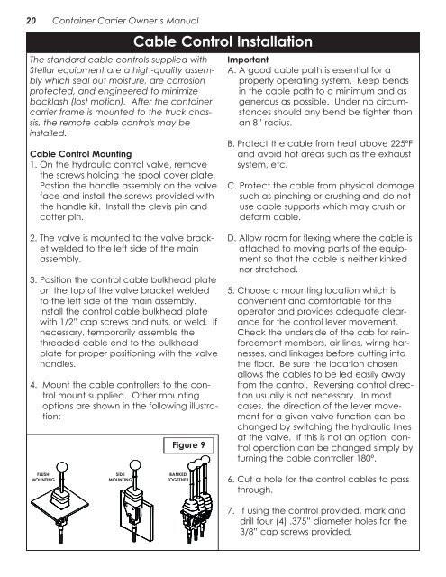
4. Mount the cable controllers to the control<br />
mount supplied. Other mounting<br />
options are shown in the following illustration:<br />
FLUSH<br />
MOUNTING<br />
<strong>SI</strong>DE<br />
MOUNTING<br />
Cable Control Installation<br />
Figure 9<br />
BANKED<br />
TOGETHER<br />
Important<br />
A. A good cable path is essential for a<br />
properly operating system. Keep bends<br />
in the cable path to a minimum and as<br />
generous as possible. Under no circumstances<br />
should any bend be tighter than<br />
an 8” radius.<br />
B. Protect the cable from heat above 225ºF<br />
and avoid hot areas such as the exhaust<br />
system, etc.<br />
C. Protect the cable from physical damage<br />
such as pinching or crushing and do not<br />
use cable supports which may crush or<br />
deform cable.<br />
D. Allow room for flexing where the cable is<br />
attached to moving parts of the equipment<br />
so that the cable is neither kinked<br />
nor stretched.<br />
5. Choose a mounting location which is<br />
convenient and comfortable for the<br />
operator and provides adequate clearance<br />
for the control lever movement.<br />
Check the underside of the cab for reinforcement<br />
members, air lines, wiring harnesses,<br />
and linkages before cutting into<br />
the floor. Be sure the location chosen<br />
allows the cables to be led easily away<br />
from the control. Reversing control direction<br />
usually is not necessary. In most<br />
cases, the direction of the lever movement<br />
for a given valve function can be<br />
changed by switching the hydraulic lines<br />
at the valve. If this is not an option, control<br />
operation can be changed simply by<br />
turning the cable controller 180º.<br />
6. Cut a hole for the control cables to pass<br />
through.<br />
7. If using the control provided, mark and<br />
drill four (4) .375” diameter holes for the<br />
3/8” cap screws provided.