BRUKSANVISNING VÄRMEPUMP MSR3-12 - Byggmax
BRUKSANVISNING VÄRMEPUMP MSR3-12 - Byggmax
BRUKSANVISNING VÄRMEPUMP MSR3-12 - Byggmax

You also want an ePaper? Increase the reach of your titles
YUMPU automatically turns print PDFs into web optimized ePapers that Google loves.
REFRIGERANT PIPE CONNECTION<br />
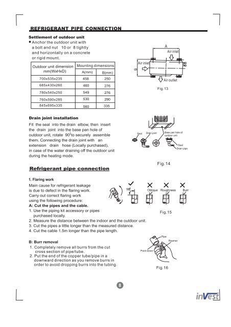
Settlement of outdoor unit<br />
Anchor the outdoor unit with<br />
a bolt and nut ¦ 10 or ¦ 8 tightly<br />
and horizontally on a concrete<br />
or rigid mount.<br />
Outdoor unit dimension<br />
mm(WxHxD) A(mm)<br />
700x535x235<br />
685x430x260<br />
780x540x250<br />
760x590x285<br />
845x695x335<br />
Drain joint installation<br />
Fit the seal into the drain elbow, then insert<br />
the drain joint into the base pan hole of<br />
outdoor unit, rotate 90 ¡ to securely assemble<br />
them. Connecting the drain joint with an<br />
extension drain hose (Locally purchased),<br />
in case of the water draining off the outdoor unit<br />
during the heating mode.<br />
Refrigerant pipe connection<br />
1. Flaring work<br />
Mounting dimensions<br />
458<br />
460<br />
B(mm)<br />
250<br />
276<br />
549 276<br />
530 290<br />
560<br />
335<br />
8<br />
Seal Drain joint Base pan hole of<br />
outdoor unit<br />
Fig.14<br />
Seal<br />
Drain pipe<br />
90 Oblique<br />
¡<br />
Main cause for refrigerant leakage<br />
is due to defect in the flaring work.<br />
Carry out correct flaring work<br />
using the following procedure:<br />
A: Cut the pipes and the cable.<br />
C Roughness Burr<br />
1. Use the piping kit accessory or pipes<br />
purchased locally.<br />
Fig.15<br />
2. Measure the distance between the indoor and the outdoor unit.<br />
3. Cut the pipes a little longer than the measured distance.<br />
4. Cut the cable 1.5m longer than the pipe length.<br />
B: Burr removal<br />
1. Completely remove all burrs from the cut<br />
cross section of pipe/tube.<br />
2. Put the end of the copper tube/pipe in a<br />
downward direction as you remove burrs in<br />
order to avoid dropping burrs into the tubing.<br />
B<br />
Air inlet<br />
Point down<br />
A<br />
Fig.13<br />
Air inlet<br />
Air outlet<br />
Pipe<br />
Fig.16<br />
Reamer