Full PDF - IOSRJEN
Full PDF - IOSRJEN
Full PDF - IOSRJEN

Create successful ePaper yourself
Turn your PDF publications into a flip-book with our unique Google optimized e-Paper software.
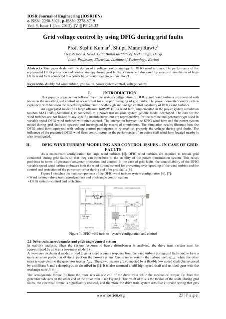
Grid voltage control by using DFIG during grid faults<br />
The pitch control system is not able to damp the torsional oscillations, because of several delay mechanisms in the<br />
pitch [12]. The pitch control damps the slow frequency variations in the generator speed, while the damping controller is<br />
able to damp the fast oscillations in the generator speed.<br />
Figure 4 illustrates the effect of the damping controller in case of a 100ms three phase grid fault at the high voltage terminal<br />
of the 3-windings transformer of a 2MW DFIG wind turbine. It is assumed that the wind turbine works at its rated power at<br />
the fault instant. As the fault operation is small compared to the wind speed fluctuations, the wind speed can be assumed<br />
constant in the grid fault simulations. The generator speed and the mechanical torque are illustrated for the situations with<br />
and without damping controller respectively.<br />
Figure 4: Damping controller effect.<br />
Note that without the damping controller, the torsional oscillations excited by the grid fault are only slightly<br />
damped still 10 seconds after the grid fault incident. It is clearly visible that the oscillations are quickly damped over few<br />
seconds when the damping controller is used. Furthermore the amplitude of the mechanical torque is much smaller when<br />
using the damping controller. In contrast, when no damping controller is used, the mechanical torque crosses only once<br />
through zero when the damping controller is used, and therefore the mechanical stress of the drive train is substantially<br />
reduced in this case. The damping controller is thus minimizing the grid fault effect both on the mechanical and on the<br />
electrical side of the turbine. The protection system together with the damping controller enhances thus the DFIG fault<br />
overcoming capability.<br />
During a grid fault, the tasks of RSC and GSC can be changed, depending on whether the protection system (i.e.<br />
crowbar) is triggered or not. In the case of less severe grid faults (i.e. not triggered crowbar) or reactive power unbalance in<br />
the system, the RSC and the GSC have the same tasks as in normal operation. In the case of severe fault (i.e. triggered<br />
crowbar), a specific grid support strategy has to be designed and developed.<br />
III. DFIG WIND TURBINE – GRID SUPPORT<br />
The technical specifications for the wind turbines, as defined by the power system operator, require wind turbines<br />
to behave as active components [13] and to support the grid. In this paper, the attention is mainly drawn to the DFIG voltage<br />
grid support during grid faults.<br />
In general, different possible voltage control strategies exist for regulating voltage at the terminals of DFIG wind<br />
turbines. The voltage can hence be controlled by either the RSC [14] or the GSC [15] or by both of them [8]. There it is<br />
limited information in the literature about the latter voltage control method. The attention in this paper is therefore drawn to<br />
the voltage control strategy, where the reactive power contribution is performed by both converters in a co-ordinated<br />
manner. The idea is that the RSC is used as default reactive power source, while the GSC is used as a supplementary reactive<br />
power source during the blocking of the RSC.<br />
At a severe grid fault, if the generator is not tripped, the DFIG wind turbine has to continue its operation with a<br />
short circuited generator, trying to sustain grid connection. When the crowbar is triggered, the RSC is blocked. In such<br />
situation, the RSC’s controllability is lost and the DFIG grid support capability is thus strongly reduced. A solution to<br />
enhance the DFIG grid support capability during grid faults is to design a control strategy where the grid voltage (reactive<br />
power) control is taken over by the GSC. The GSC does not block at a grid fault, but it continues its operation as STATCOM<br />
as long as the RSC is blocked. When the crowbar is removed, the RSC starts to operate and the GSC is set again to be<br />
reactive neutral. The remove of the crowbar protection and hence the re-start of the RSC can be performed according<br />
different criteria, such as the magnitude of the grid voltage or of the rotor currents. A too soon RSC restarting may cause<br />
tripping of the converter again at the fault clearance.<br />
As illustrated in Figure 5, the DFIG voltage grid support strategy is implemented in this work as an extension of<br />
the DFIG control structure used in normal operation and presented in Figure 2.<br />
Figure 5: Extended DFIG control structure for voltage grid support during grid faults.<br />
www.iosrjen.org 28 | P a g e
Grid voltage control by using DFIG during grid faults<br />
The power system test model, described in [16], is in this paper extended by connecting at a 135 kV busbar an<br />
additional offshore wind farm, made up exclusively of 80 equal 2MW DFIG wind turbines. Similarly to the 165 MW<br />
offshore active stall wind farm, the new added offshore wind farm is modelled also by one machine approach based on the<br />
aggregation technique. It is assumed that the one DFIG turbine with re-scaled power capacity is modelled and equipped with<br />
the fault removing capability and the presented voltage grid support strategy.<br />
4.2 Simulation Results<br />
Two set of simulations are presented in the following. The first set illustrates how the DFIG wind farm provides<br />
voltage grid support, while the second shows how the DFIG voltage control capability during grid faults affects the<br />
performance of the active stall wind farm located in vicinity.<br />
In each simulation a severe three phase short circuit grid fault is considered to happen in the transmission grid at<br />
the end of Line 4 close to the wind farms – see Figure 6. The grid fault lasts for 100ms and gets cleared by permanent<br />
isolation (tripping the relays) of the faulty line (Line 4 in Figure 6). Note that, by tripping Line 4, the power system becomes<br />
weaker (higher impendance) and some components (e.g. Line 3) are fully loaded.<br />
As the on-land wind turbines do not have any ride-through control implemented, it is assumed that they are<br />
disconnected from the system by their protection system, in the moment of the grid fault. In the moment of the<br />
disconnection, it is also assumed that the frequency stability in the grid is assured by large generator inertia.<br />
The following scenario is common for the both simulations. In the moment of the grid fault, a voltage drop occurs.<br />
Immediately after the fault, when the rotor current magnitude is above the current protection limitation, the crowbar<br />
protection system of the DFIG is triggered, the rotor is short circuited, the RSC is blocked and the GSC operates as<br />
STATCOM. The damping controller starts to damp the drive train oscillations caused by the fault. When the fault is cleared<br />
and the DFIG wind farm terminal voltage recovers to a certain value, the crowbar protection is disabled, the RSC starts to<br />
control the grid voltage and the GSC is again set to be reactive neutral.<br />
4.2.1 DFIG voltage grid support capability<br />
In order to illustrate the DFIG voltage grid support capability, a worst case for the voltage stability is considered. It<br />
is assumed that, the 165MW offshore active stall wind farm, placed in the vicinity of the DFIG wind farm has its power<br />
reduction control disabled. This fact has a negative influence on the voltage stability in the grid, as the generator speed<br />
oscillations of the active stall wind turbine caused by the grid fault are directly reflected in the grid voltage.<br />
Figure 7 illustrates the voltage, the active and the reactive power of the DFIG wind farm in the wind farm terminal (WFT),<br />
for the situations with and without DFIG voltage grid support respectively.<br />
As expected, the influence of voltage grid support is visible both during grid fault, when the GSC operates as STATCOM<br />
and supplies reactive power after the disconnection of the crowbar, namely when the RSC controls the voltage on the grid.<br />
When no DFIG voltage grid support is enabled, the grid voltage oscillates as expected. After a while, it stabilizes to a higher<br />
voltage level. This aspect can be explained both by the reactive power surplus existent in the system as result of the on-land<br />
wind turbines disconnection and by the fact that, as result of the fault clearance (tripping Line 4), the transport of the active<br />
power from the wind farms to the grid is done through a higher resistance transmission line.<br />
Figure 7: DFIG wind farm terminal with and without voltage control when the power reduction of the active stall wind farm<br />
is disabled.<br />
Figure 7 shows that the existing reactive power surplus in the system is absorbed by the DFIG, when the voltage<br />
grid support control is enabled. Note that the DFIG voltage control re-establishes the grid voltage to 1p.u. very quickly<br />
without any fluctuations. No significant effect of the voltage control appears on the active power production. However, there<br />
it is a slight improvement in active power when voltage control is used. The small “drops” in the power, visible in both cases<br />
just after the fault is cleared, are generated by the damping controller used to damp torsional oscillations in the generator<br />
speed of the DFIG after the grid fault. Similarly to Figure 4, these oscillations are damped over few seconds. The initial level<br />
of the active power is reached after few more seconds.<br />
4.2.2 DFIG grid support capability effect on nearby wind farm performance<br />
The goal of the following simulation is to illustrate how the DFIG wind farm (DFIG-WF) voltage grid support<br />
control influences the performance during a grid fault of a nearby active stall wind farm, placed as illustrated in Figure 6.<br />
The next two figures contain therefore only information concerning the nearby active stall wind farm (AS-WF) during the<br />
www.iosrjen.org 30 | P a g e
Grid voltage control by using DFIG during grid faults<br />
grid fault, namely the active and reactive power in the wind farm terminal, the generator speed and the mechanical power of<br />
the active stall wind turbines, respectively.<br />
The four following control sceneries are illustrated:<br />
a. DFIG-WF without voltage grid support control and AS-WF without power reduction control.<br />
b. DFIG-WF with voltage grid support control and AS-WF without power reduction control.<br />
c. DFIG-WF with voltage grid support control and AS-WF with power reduction control.<br />
d. DFIG-WF without voltage grid support control and AS-WF with power reduction control.<br />
Figure 8: Active and reactive power of the active stall wind farm (AS-WF) in different situations.<br />
The following observations can be made:<br />
The voltage grid support control of the DFIG wind farm (case (b) and (c)) has a damping effect on the active stall<br />
wind farm, no matter whether this has or does not have power reduction control.<br />
The active power, the generator speed and the mechanical power are almost identical during the grid fault, no<br />
matter which case is simulated. The fact that the mechanical power is unchanged in this period means that the<br />
drive train system is equally stressed in all four cases.<br />
The worst case for the active stall wind farm is clearly the case (a), when the DFIG wind farm has no voltage grid<br />
support control and the active stall wind farm has no power reduction control.<br />
The best case for the active stall wind farm is clearly the case (b) (and not case (c)!), when DFIG wind farm is<br />
equipped with voltage grid support control, and the power reduction control of the active stall wind farm is not<br />
enabled. Note that, in case (b), the AS-WF is not subjected to torsional oscillations and there is no loss in the active<br />
power production. The influence of the DFIG voltage grid support control on the active stall wind farm is thus<br />
even better when the latter does not have any special control implemented to overcome a grid fault.<br />
Figure 9: Generator speed and mechanical power of the active stall wind farm (AS-WF) in different situations.<br />
The overall conclusion from Figure 8 and Figure 9 is that the DFIG wind farm equipped with voltage grid support<br />
control can help and improve the performance of a nearby active stall wind farm through a grid fault, without any need to<br />
implement an additional fault removing control strategy in the active stall wind farm.<br />
V. CONCLUSIONS<br />
This paper presents a voltage grid support control strategy for DFIG wind turbines, which enhances the fault<br />
removing and the voltage grid support capability of DFIG wind turbines during grid faults. The idea of this strategy is that<br />
both DFIG converters participate in the voltage control in a co-ordinated manner. By default, the grid voltage is controlled<br />
by the rotor-side converter as long as this is not blocked by the protection device (i.e. crowbar) otherwise the grid-side<br />
converter is taking over the control of the voltage.<br />
The controllability of the DFIG during grid faults is enhanced by the design of a proper co-ordination of three<br />
additional controllers, such as damping controller, rotor-side converter voltage (RSC) controller and grid-side converter<br />
(GSC) reactive power boosting. The idea of the damping controller is based on the fact that grid faults cause torsional<br />
oscillations and high mechanical stress in the wind turbine’s drive train. These oscillations are transmitted uncontrolled to<br />
www.iosrjen.org 31 | P a g e
Grid voltage control by using DFIG during grid faults<br />
the generator speed if the active power reference for the RSC control is defined as in normal operation, namely based on<br />
MPT look-up table. A way to damp these oscillations is to generate an active power reference as output of a damping<br />
controller. Such a controller has to be tuned to damp actively the torsional oscillations excited in the drive train system. The<br />
RSC voltage controller controls the grid voltage as long as the RSC is not blocked. The GSC reactive power boosting<br />
controller contributes with its maximum reactive power capacity in case of severe grid faults.<br />
The DFIG wind farm fault overcoming capability and its contribution to voltage control is assessed and evaluated<br />
by means of simulations with the use of a generic but realistic transmission power system model in the power system<br />
simulation toolbox MATLAB (Simulink ).The DFIG wind farm is modeled based on aggregation approach, i.e. as one DFIG<br />
turbine with re-scaled power capacity. The simulation results illustrate how the DFIG wind farm equipped with the presented<br />
voltage grid support control strategy participates to re-establish properly the voltage during a grid fault. The influence of<br />
such a control setup on the performance of an active stall wind farm placed nearby is also investigated. The conclusion is<br />
that the DFIG wind farm equipped with voltage grid support control can help a nearby active stall wind farm to remove a<br />
grid fault, without implementation of any additional fault removing control setup in the nearby active stall wind farm.<br />
REFERENCES<br />
[1]. "Wind turbines connected to grids with voltages above 100 kV - Technical regulations for the properties and the<br />
control of wind turbines,, Energinet.dk, Transmission System Operator of Denmark for Natural Gas and<br />
Electricity, Technical Regulations TF 3.2.5, 2004, 35 p. Available: www.energinet.dk<br />
[2]. E.ON. Netzanschlussregeln Hoch-und Hoechst-spannung. 2003, Report ENENARHS2006, April 2006, 46 pages,<br />
www.eon-netz.com<br />
[3]. Hansen A.D., Jauch C., Sørensen P., Iov F., Blaabjerg F. Dynamic wind turbine models in power system<br />
simulation tool DIgSILENT, Risø-R-1400(EN), 2003.<br />
[4]. Leonhard W. Control of electrical drives, Springer Verlag, 2001, ISBN 3540418202.<br />
[5]. Hansen A.D., Hansen L.H., Wind turbine concepts market penetration over ten years (1995 to 2004),Wind<br />
Energy, No. 10, 2007, pp.81-97.<br />
[6]. Hansen A.D., Michalke G., Sørensen P., Lund T., Iov F. Co-ordinated voltage control of DFIG wind turbines in<br />
uninterrupted operation during grid faults, Wind Energy, No. 10, 2007, pp. 51-68.<br />
[7]. Hansen A.D., Sørensen P., Iov F., Blaabjerg F. Centralised power control of wind farm with doubly fed induction<br />
generators, Renewable Energy, 2006, vol. 31, pp 935-951.<br />
[8]. Akhmatov V., Analysis of dynamic behavior of electric power systems with large amount of wind power, PhD<br />
thesis, 2003, Ørsted DTU.<br />
[9]. Heier S. Grid Integration of Wind Energy Conversion Systems,John Wiley&Sons, Ltd. Chichested UK, 1998.<br />
[10]. Hansen A.D., Michalke G., Fault ride-through capability of DFIG wind turbines, Renewable Energy, vol 32, 2007,<br />
pp 1594-1610 .<br />
[11]. Akhmatov V., Variable-speed wind turbines with doubly fed induction generators. Part II: Power System Stability.<br />
Wind Engineering, Vol. 26, No. 3, 2002, pp 171-188.<br />
[12]. Akhmatov V., Variable-speed wind turbines with doubly fed induction generators. Part IV: Uninterrupted<br />
operation features at grid faults with converter control coordination. Wind Engineering, Vol. 27, No. 6, 2003, pp<br />
519-529.<br />
[13]. Sørensen P., Bak-Jensen B., Kristiansen J., Hansen A.D., Janosi L., & Bech J. Power plant characteristics of wind<br />
farms. Wind Power for the 21 st<br />
Century. Proceedings of the International Conference, Kassel, 2000, 6pp.<br />
[14]. Eping C., Stenzel J., Poeller M., Mueller H., Impact of Large Scale Wind Power on Power System Stability, Fifth<br />
International Workshop on Large-Scale Integration of Wind Power and Transmission Networks, Glasgow, 2005,<br />
9pp.<br />
[15]. Kayikci M., Anaya-Lara O., Milanovic J.V., Jenkins N., Strategies for DFIG voltage control during transient<br />
operation, CIRED, 18 th<br />
Int. Conference on Electricity Distribution, Turin, 2005, 5pp.<br />
[16]. Akhmatov V., A small test model for the transmission grid with a large offshore wind farm for education and<br />
research at Technical University of Denmark., Wind Engineering, vol.30, No. 3, 2006, pp. 255-263.<br />
www.iosrjen.org 32 | P a g e