Wadkin FD Planer Moulder Literature
Wadkin FD Planer Moulder Literature
Wadkin FD Planer Moulder Literature

You also want an ePaper? Increase the reach of your titles
YUMPU automatically turns print PDFs into web optimized ePapers that Google loves.
--------------- -- ----------<br />
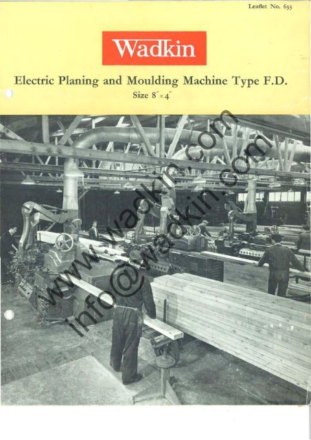
Leaflet No. 633<br />
Electric Planing and Moulding Machine Type P.D.<br />
Size 8" x4"<br />
www.wadkin.com<br />
info@wadkin.com
• n<br />
8"x 4" Planing and Moulding Machine F.D.<br />
The basic machine in any well balanced woodworking plant is an efficient general purpose<br />
moulder. Opinion varies as to what, under modern manufacturing conditions, constitutes<br />
moulder efficiency. In one branch of the trade, accuracy and finish is the criterion-in<br />
another, quantity and speed of production is the paramount consideration-where runs<br />
are short and changes of pattern frequent, versatility and adaptability afC the measure of<br />
efficiency.<br />
All these varying requirements are met by this \Vadkin F.D. type electric moulder, as<br />
witness the ever-increasing number of these machines being supplied to the different<br />
branches of the woodworking industry.<br />
In the light of the many operating advantages and vastly improved performance of this<br />
modern machine, users soon find that it is uneconomic to operate old style moulders.<br />
Such machines are far too wasteful of both time and labour to justify a place in a properly<br />
equipped shop.<br />
www.wadkin.com<br />
It would pay you, too, to replace your unprofitable old machines with a modern <strong>Wadkin</strong>.<br />
Its capabilities not only make it a sound investment, but its obvious efficiency and<br />
modern appearance could not fail to impress all who see it in operation in your plant<br />
with the fact that here is a progressive manufacturer whose key machines arc in keeping<br />
with the tempo of the times.<br />
info@wadkin.com<br />
2
)<br />
www.wadkin.com<br />
3<br />
--------------<br />
ELECTRIC PLANING AND<br />
info@wadkin.com
i\10UI,I)ING MACHINE 1',0,<br />
www.wadkin.com<br />
•<br />
.--.a.:L.In<br />
info@wadkin.com<br />
8"x 4" <strong>Planer</strong> and <strong>Moulder</strong><br />
Type F.D.<br />
4
FrMII cover removed fO Sl,OlV detail offetd.<br />
o<br />
FEATURES at the INFEED<br />
Entire fud world are oj robust col/struc/ion<br />
designed to give maximum tractive effort.<br />
1 Exceptionally light alld easy rise and fall of feed<br />
1uilh conveniemly placed halldwheel camral.<br />
) Independellt spTi'lg pressure to top rolls, applied<br />
by convenient hand10heels.<br />
4 Feed selection accessible from from of machine.<br />
Speed range: 18 to 150 feet,," mil/me; feed<br />
speeds up to 200 feet per mil/lilt can be supplied<br />
to special order.<br />
S Feed drive is by two-step cOile drive to a six-spud<br />
gearbox. Rear feed works drive is totally cnclosed<br />
and all chaillS and gears '1m in oil bath.<br />
-<br />
6 Cover is quickll remowd and top rolls easily<br />
detQcllable for fitting bevel rollers.<br />
www.wadkin.com<br />
7 All feed roller shafls are ball and roller bearing<br />
mOI/II/ed.<br />
8 Independellt vertical adjllstmem to boltom feed<br />
rollers.<br />
info@wadkin.com<br />
9 Adjllstml!1lt for pitching bottom feed rollers to<br />
keep timber liP to fl!1lce whl!1l feeding.<br />
10 Top feed rolh are 8i; diameter and bot/Dill feed<br />
rolls 8 w<br />
diameter. First top and boUOIII are fllIled,<br />
and second top and bot/om plain. Top rolls 11ft r<br />
for oversize suuk.<br />
II Peed call be started, inched forward and reversed<br />
frolll this cOlllrol slation.<br />
NOle: A palented pneumallC recd works 10 gh'c \'ariablc pressure and inslanllirt 10 Ihe top reed<br />
works can be offered as shown on page 16<br />
6<br />
)<br />
)
FEATURES at the FIRST HEAD<br />
www.wadkin.com<br />
Rise ami fall adjustlllclIl for lablc 011 inclilled<br />
tr,;edge slide.<br />
2 Roller pressure /II/its over 1m! bottolll head, each<br />
quickly adjusted to sliit reidtlt of stock.<br />
] Rise alld fall adjmlmcm for roller pressure III/irs.<br />
4 Illdepmdent adjllst11ltm to spr;"g loading all<br />
roller presllIr
•<br />
FEATURES at the OUTFEED<br />
www.wadkin.com<br />
Top head radial arm eiliphreaker filted with<br />
illdependellt spring pressure shoes with renewable<br />
Stellife-tipped toe pieces. Glliphreaker mings clear<br />
jar access to block.<br />
1 String away, patent outboard bearing Ill/it with<br />
sleeve moum;l1g having split collet lock to eliminate<br />
play betUlell cutter spindle and bearing.<br />
) Rile alld 10/1 of spindle carriage is by 1f."O enclosed<br />
vertical screu-s operated by totally mclosed spiral<br />
gears.<br />
9<br />
4 Crou adjllslmell/ /0 spindle 1/1Iit to facilitate quick<br />
set-lips. Adjustments can be made whIlst machine<br />
is rullning.<br />
S Omfeed table tvith rise and Jail motioll by hand<br />
'II.:hul and screflJ. Counterbalanced table swings<br />
array to give access to clIlterblock.<br />
info@wadkin.com<br />
6 Jaimer can be fitted to all heads.<br />
7 Duplicate feed comro/ to facilitate set/illg liP alld<br />
duplicate master stop button. (Similar c01l/rols are<br />
or ill/ted end.)
ELECTRIC PLANING AND MOULDING MACI-IINE F.D.<br />
The <strong>Wadkin</strong> Spindle Unit<br />
The heart of the Wad1
ELECTRIC PLANING AND MOULDING l\.'1ACllINE F.D.<br />
The <strong>Wadkin</strong> Spindle Unit<br />
The heart of the Wadhin <strong>Moulder</strong>-and tile hey to its efficiency<br />
Good moulder work depends on a combination of many engineering features, but no<br />
maner how efficiently the machine may function in other respects, ultimate satisfactory<br />
performance depends primarily on the main cutter spindles.<br />
www.wadkin.com<br />
The distinguishing characteristic of \Vadkin <strong>Moulder</strong>s is that the spindles are all selfcontained<br />
direct motorised units high frequency operated. The \Vadkin spindle housing<br />
is a cylinder. In fact every part of the entire spindle assembly-spindle, bearings, collars,<br />
caps, housing, motor-is cylindrically shaped. Each part has therefore a uniformity<br />
of metal distribution and all faces are developed round a common centre.<br />
info@wadkin.com<br />
This unique design accounts for: first, steady, vibrationless spindle rotation at 6,000 or<br />
4,500 r.p.m., giving uniform depth and spacing of knife marks which governs quality<br />
of finish j secondly, flexibility and speed of set-up, and thirdly, dependability with<br />
simplified maintenance.<br />
10
ELECTRIC PLANING ANI) MOULDING MACI-IINE 1'.0.<br />
A • C o G F E H u<br />
K J l H NO P Q • v w y X<br />
www.wadkin.com<br />
info@wadkin.com<br />
11
ELECTRIC FEATURES<br />
The <strong>Wadkin</strong> <strong>Moulder</strong> is supplied completely equipped<br />
electrically with motors, frequency changer, control<br />
gcar and main switch with fuses.<br />
All electrical equipment is made by leading British<br />
manufacturers with extensive service facilities throughout<br />
the world.<br />
All electrical gcar is self-cont:'lincd with the machine.<br />
The machine is completely wired up in accordance<br />
with the best British machine tool practice. Ir is<br />
therefore supplied ready for connection to the<br />
purchaser's electricity supply.<br />
All head motors consist of powerful stator and rotor<br />
units specially designed for moulder duty housed in<br />
totally endosed aluminium frames and externally fan<br />
cooled.<br />
12<br />
of the <strong>Wadkin</strong> <strong>Moulder</strong><br />
Motors arc directly 011 the spindles, for vibrationlcss<br />
running and are high frequency operated to give<br />
speeds of 6,000 and 4,500 r.p.m. when connected to<br />
a 50-crclc supply.<br />
The control gcar is designed to give maximum<br />
operating convenience.<br />
Each headstock is individually controlled from a<br />
rolary selector switch having "Run" and "Brake"<br />
positions, used in conjunclion with a separate start<br />
and Stop push button and magnetic comaetor.<br />
www.wadkin.com<br />
The feed motor is controlled in a similar manner<br />
wilh the exception that Ihe selector switch enables<br />
the motor to be selected for "Forward", "Reverse"<br />
or "Inch" mOlions.<br />
info@wadkin.com<br />
Full protective features arc embodied in control gcar.
ELECTRIC I'LANING AND<br />
The Main Frame<br />
The main frame is heavily constructed and is<br />
engineered to provide maximum stability for the<br />
feed works and cutterheads. All attachment faces<br />
are accurately machined. The base of the frame is<br />
also machined to facilitate an accurate foundation.<br />
Dust-tight compartments are built into the main<br />
frame to receive the electrical control gear.<br />
Feed Works<br />
Feed works are fully enclosed and ball bearing<br />
mounted throughout. Four feed roils are driven<br />
by chain running in oil bath. Independent adjustment<br />
is provided to each bottom roll and provision<br />
is made for pitching the bottom rolls whilst the<br />
machine is running. The top feed roils are mounted<br />
in a vertical vee slide, with rise and fali movement<br />
by spiral gear and handwheel operated from the<br />
front of the machine.<br />
The feed is obtained from a 7t h.p., 1,500 r.p.m.,<br />
totally-enclosed motor, driving through a two-step<br />
cone to a six-speed ball bearing gearbox giving:<br />
18, 25, 32, 45, 55, 75) , .<br />
36,50,64,90,110,150 leet per mmute.<br />
The gearbox selection levers are accessible from<br />
the front of the machine.<br />
The table before the first bottom head is mounted<br />
on an inclined slide and has an independent adjustment<br />
to the feed rolls.<br />
A feature of the <strong>Wadkin</strong> feed works is that the tOp<br />
roll cover is quickly removed and top rolls easily<br />
detached for fitting bevel rollers.<br />
Pneumatic Feed Works<br />
A pneumatically-controlled feed works arrangement<br />
(Patent No. 986651) can be offered.<br />
This arrangement provides pneumatic pressure to<br />
the top feed rolls and a control valve and pressure<br />
gauge is provided to enable instantaneous pressure<br />
adjustment to be made. A built-in relief valve<br />
ensures constant pressure on the feed rolls regardless<br />
of timber thickness variation. An additional<br />
valve enables full pressure to be applied to give<br />
traction increase. The height of the feed rolls is<br />
set to the nominal thickness of the timber by scale<br />
and pointer.<br />
Instantaneous loss of traction is achieved by<br />
pneumatic lift of the top feed rolls, and suitable<br />
mushroom-type operated buttons for this feature<br />
are positioned at the infeed and outfeed end of the<br />
machine.<br />
In addition pneumatic lift of feed rolls can be<br />
initiated automatically in the event of board overriding<br />
or when one or more cutterhead motors arc<br />
overloaded.<br />
When a fast feed table is fitted a pneumatic clutch<br />
can be arranged to disengage simultaneously with<br />
the loss of traction.<br />
Specification<br />
16<br />
------------------- ---------<br />
MOULDING MACHINE I'.D,<br />
The Bed<br />
The entire length of the bed from the feed works<br />
to the outfeed table is made of renewable chrome<br />
iron sections, heat treated and precision ground all<br />
over. The edges arc dovetail in section, so that they<br />
can be securely clamped in position and readily<br />
adjusred lengthwise, to and from the bottom cutterblocks.<br />
Plates in front of the side heads move wirh<br />
the heads and thus provide a continuous bed without<br />
gaps from end to end of the machine. The<br />
outfeed table is mounted on a slide permitting easy<br />
and accurate setting of the table in relation to the<br />
cutterblock. The adjustmellt is by screw and handwheel.<br />
The whole of the outfeed table can be<br />
swung downwards for access to the cutterblock,<br />
this movement being coullter-balanced by balance<br />
weight at the rear of the machine.<br />
Cutter Spindle Design<br />
All heads are completely self-contained motorised<br />
units. All head units are designed wirh three special<br />
high-speed duty ball bearings, and horizontal heads<br />
have in addition an outboard bearing also of the<br />
high-speed duty type.<br />
The main bearings arc mounted in one housing to<br />
ensure perfect alignment. They are oil lubricated<br />
and in the case of all outboard bearings, also side<br />
head bearings, a <strong>Wadkin</strong> patented method of oil<br />
vapour lubrication is employed, to ensure a long<br />
bearing life. Each outboard beating is provided<br />
with a taper collet sleeve on which the bearing<br />
itself is mounted.<br />
www.wadkin.com<br />
info@wadkin.com<br />
Parem pllelllllatic • feed fvorks give variable pressure all
Suaight joiming 011 side head.<br />
Profilt joimil'G on last lOp head.<br />
Rear t:iew ollr'adkill ·r <strong>Planer</strong> alld .llOlildet F.D.<br />
I\'Ott tatally·",cloud 1II0/ors 0" all heads alld/ud drit,t.<br />
18<br />
Hopper Feed for Short Stock<br />
A hopper feed unit can be built imo the feed [able<br />
in from of the standard feed rolls for automatically<br />
feeding short stock into the machine. This is driven<br />
by a chain from the main feed works to ensure<br />
synchronisation. All machines arc scm out prepared<br />
for the addition of this hopper feed at a later date.<br />
Automatic Feed Table.<br />
Feed table can be supplied for timber up (024' 0"<br />
in length and can be arranged to be driven from<br />
the main feed works drive.<br />
Jointing<br />
Provision is made on spindle carriages to receive<br />
joiming attachmenTs. These may !:>c fitted at any<br />
time. STraight or profile jointers can be supplied<br />
for all heads.<br />
For straight joiming the jointing stone is carried in<br />
a stone-holder slide and has a cross adjustment by<br />
screw motion to cover the full width of the cutterblock.<br />
The stone has a micrometer screw adjustment<br />
for applying the cut. The whole unit drops<br />
easily into twO vee brackets for accurate location<br />
and is just as quickly removed.<br />
The profile jointer carries a turret type stone holder><br />
which enables a series ofshaped stones to be fined<br />
for consecutive applications to a profile head or<br />
shaped cutters. The turret head has cross adjustment<br />
for locating purposes, also fine screw adjustment<br />
for applying the cut. The profile jointer<br />
locates in the same brackets as the straight jointer.<br />
www.wadkin.com<br />
info@wadkin.com
ELECTRIC ('LANING AND<br />
Electrical Equipment<br />
The machine is supplied completely equipped<br />
electrically with motors, frequency changer and<br />
control gear. All electrical gear is made by leading<br />
British manufacturers with extensive service<br />
facilities throughout the world.<br />
The head motors consist of stator and rotor units<br />
housed in totally·enelosed frames which are<br />
externally fan-cooled and run at speeds of 4,500<br />
and 6,000 r.p.m. on 50-cycle supply which are<br />
provided by a frequency changer driven by two·<br />
speed motor built into the machine. When supplied<br />
for operation on 60-cycle supply, speeds of 4,800<br />
and 6,000 r.p.m. are provided. The frequency<br />
changer has an output of 20/15 kw and is arranged<br />
to give frequency at the heads of 100 and 75 cycles<br />
from 50 cycles, or 100 and 80 cycles from 60 cycle<br />
primary supplies. I t also provides the low voltage<br />
for the braking system on the machine.<br />
Control Gear<br />
The control gear is designed to give the utmost<br />
facility to the operator when running the machine<br />
and setting up. Each headstock is individually<br />
controllecl from a rOtary selector switch having run<br />
and brake positions used in conjunction with a<br />
separate start push button and magnetic contactor.<br />
The feed motor is controlled in a similar manner<br />
with the exception that a rotary switch selects the<br />
direction of the feed and also permits the normal<br />
start button to be used as an inch button. The start<br />
and stop and inch buttons arc fixed in convenient<br />
positions at the infeed and outfeed ends of the<br />
machine. Prominent master stop buttons arc<br />
provided at each end of the machine.<br />
Individual overload protection is provided for all<br />
motors and frequency changer. In the event ofany<br />
item being overloaded the entire machine will shut<br />
down.<br />
Cabling<br />
Special care is givcn to the cabling of the machines<br />
which is done in accordance with the best British<br />
machine tool practice. It is fully protected from<br />
mechanical damage. On final assembly the<br />
machine is flash tested at 2,500 volts to ensure that<br />
the insulation and electrical spacings throughout<br />
the machine are adequate. Every machine is run<br />
on the electric supply for which it is ordered before<br />
it is despatched.<br />
Exhaust Hoods<br />
Aluminium exhaust hoods are supplicd with the<br />
machine. The exhaust for the bottom heads is<br />
obtained by chutes cast in the main frame.<br />
19<br />
MOULDING MACHINE F.D.<br />
Guards<br />
All heads are efficiently guarded. When jointers<br />
are supplied, special guards for the first and last<br />
bottom heads are necessary and can be supplied<br />
to order.<br />
Exhaust Collector Unit<br />
A special collector has been designed for this<br />
machine, which is a big advance on the usual<br />
practice of coupling each head independently into<br />
the main. This unit comprises two shcct steel<br />
hollow circular columns supporting a waypiece into<br />
which are fitted ovcrhead flexible connections to<br />
the top and side hcads, and rigid connections to<br />
the bottom heads. The flexible pipes arc telcscopic<br />
to facilitate the removal of the exhaust hoods.<br />
www.wadkin.com<br />
Special duS( collector<br />
as ShOfVII below is<br />
recollllllel/ded for lise<br />
with the machine.<br />
info@wadkin.com