Standard grippers HGP/HGD/HGR/HGW Micro grippers ... - Festo
Standard grippers HGP/HGD/HGR/HGW Micro grippers ... - Festo
Standard grippers HGP/HGD/HGR/HGW Micro grippers ... - Festo

Create successful ePaper yourself
Turn your PDF publications into a flip-book with our unique Google optimized e-Paper software.
<strong>Standard</strong> <strong>grippers</strong> <strong>HGP</strong>/<strong>HGD</strong>/<strong>HGR</strong>/<strong>HGW</strong><br />
<strong>Micro</strong> <strong>grippers</strong> <strong>HGP</strong>M/<strong>HGW</strong>M<br />
Whether it’s standard or<br />
miniaturised objects – secure<br />
gripping is guaranteed.<br />
Info 116
<strong>Festo</strong> gripper technology:<br />
Flexible handling and secure gripping by design<br />
2<br />
The standard and micro <strong>grippers</strong> integrate seamlessly into <strong>Festo</strong>’s<br />
modular handling and assembly technology systems and service<br />
portfolio. This includes not only 2D drawings and 3D models in 80 CAD<br />
formats, but also a convenient selection software program for reliable<br />
and fast planning and design.<br />
<strong>Micro</strong> Versatile Integrated<br />
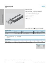
<strong>Standard</strong> <strong>grippers</strong> <strong>HGP</strong>, <strong>HGD</strong>, <strong>HGR</strong>,<br />
<strong>HGW</strong> – the first choice for a wide<br />
range of applications<br />
Low-cost<br />
Parallel, 3-point, angle or radial<br />
<strong>grippers</strong><br />
Sizes 6 to 50 mm<br />
With seamless integration into the<br />
modular handling and assembly<br />
technology systems<br />
Impressive technology<br />
Double-acting piston drive<br />
Self-centring<br />
Optional gripping action:<br />
external/internal gripping<br />
Adaptable Hall sensors for the<br />
smallest standard <strong>grippers</strong> and<br />
integratable proximity sensors for<br />
the remaining <strong>grippers</strong><br />
Externally adaptable gripper fingers<br />
Wide range of options for mounting<br />
on drive units<br />
<strong>Micro</strong> <strong>grippers</strong> <strong>HGP</strong>M/<strong>HGW</strong>M<br />
Secure gripping of extremely small<br />
workpieces in tight spaces.<br />
Compact<br />
Maximum service life with more<br />
than 10 million switching cycles<br />
Quick and easy to assemble<br />
Compact and handy<br />
Optional stroke compensation<br />
Highly cost-effective<br />
Attractive cost price and extremely<br />
long service life.<br />
Highly flexible<br />
The gripper fingers can be adapted<br />
externally and there is a wide range of<br />
options for mounting on drive units.<br />
Highly specialised<br />
Used in applications such as feeding<br />
in the assembly of electronic or precision<br />
mechanical components. Ideal<br />
for low weights and process forces<br />
and where high precision is required.<br />
Info 116 – Subject to change – 2006/03
<strong>Standard</strong>ised, application-oriented<br />
design<br />
Powerful gripping, long service life and diverse adaptation possibilities combined<br />
with excellent economy – the <strong>Festo</strong> gripper range addresses the needs of<br />
both the designer and the buyer. Don’t take our word for it – see for yourself.<br />
Advantages for designers Advantages for purchasers<br />
Reduced planning costs<br />
General reduction in fitting space<br />
High gripping forces – small size<br />
Excellent precision and load<br />
capacity<br />
Modular gripper system Simple, clearly defined interfaces<br />
Straightforward system<br />
integration<br />
Miniaturised series For handling the smallest<br />
components<br />
For use in all industries<br />
producing miniature components<br />
Reduced ordering expenses<br />
Reduced follow-up costs through<br />
long service life<br />
Favourable price/performance<br />
ratio<br />
Solution from a single source<br />
Reduced logistics<br />
Favourable entry price<br />
Reduces unnecessary costs for<br />
oversizing<br />
2006/03 – Subject to change – Info 116 3
Forces at the gripper<br />
Basic principles<br />
Calculation tools for determining gripping force<br />
What is meant by gripping force?<br />
4<br />
Action = Reaction<br />
The gripping force FG refers to the<br />
gripping force per gripper jaw.<br />
Howdoesthegrippingforceactinthecaseof2-jaw<strong>grippers</strong>?<br />
Parallel, radial and angle <strong>grippers</strong><br />
Mechanical locking<br />
Mechanical locking with V-gripper<br />
1 2<br />
Frictional locking<br />
Howdoesthegrippingforceactinthecaseof3-jaw<strong>grippers</strong>?<br />
Three-point gripper<br />
Mechanical locking<br />
Mechanical locking with V-gripper<br />
Frictional locking<br />
When selecting a gripper you need to<br />
determine the gripping force required<br />
to hold a workpiece of mass m [kg]<br />
F G = m × (g+a) × S<br />
1<br />
F G =<br />
m × (g+a)<br />
× tan α × S<br />
2<br />
2<br />
FG = m × (g+a) × tan α × S<br />
F G =<br />
m × (g+a)<br />
× sin α × S<br />
2 × μ<br />
F G = m × (g+a) × S<br />
F G =<br />
F G =<br />
m × (g+a)<br />
× tan α × S<br />
3<br />
m × (g+a)<br />
× S<br />
3 × μ<br />
and move this workpiece at an<br />
acceleration of a [m/s 2 ].<br />
FG Required gripping force [N] per<br />
gripper jaw<br />
For angle and radial <strong>grippers</strong>,<br />
gripping force FG must be converted<br />
to gripping torque MG.<br />
r, x Distance between the gripper<br />
zero point and the gripping<br />
point (lever arm)<br />
Catalogue specifications:<br />
“Gripping force as a function of<br />
the lever arm”<br />
M G = F G × r<br />
m Workpiecemass[kg]<br />
g Acceleration due to gravity<br />
(≈ 10 m/s 2 )isrequiredifacting<br />
against the acceleration a<br />
a Acceleration [m/s 2 ]arisingfrom<br />
the dynamic movement<br />
S Safety factor<br />
α Angle of V-gripper finger<br />
µ Coefficient of friction between<br />
gripper finger and workpiece<br />
Info 116 – Subject to change – 2006/03
Forces at the gripper<br />
Basic principles<br />
Max. acceleration values with different drive types<br />
Peak acceleration values occur: In an emergency stop<br />
Shortly before the end position is<br />
reached<br />
Drive function Pneumatic Servopneumatic Electrical<br />
with fixed<br />
cushioning<br />
with adjustable<br />
cushioning<br />
with shock<br />
absorber<br />
Axis with<br />
toothed belt<br />
Axis with spindle with linear<br />
motor<br />
Max. acceleration [m/s 2 ] 50 … 300 10 … 300 10 … 300 5…15 0…15 0…6 0…30<br />
Recommended safety factor<br />
Recommended range<br />
1 1.6 2 3 4<br />
Coefficient of friction µ<br />
Low dynamic response<br />
Controlled, static friction factor<br />
No fluctuation of the compressed air<br />
in the system<br />
High dynamic response<br />
Considerable variation in the friction<br />
factor<br />
Considerable fluctuation of the<br />
compressed air<br />
Considerable overlap of accelerations<br />
(linear/rotary)<br />
Workpiece surface<br />
ST STl AL ALl R<br />
Gripper pp finger g ST 0.25 0.15 0.35 0.20 0.50<br />
surface STl 0.15 0.09 0.21 0.12 0.30<br />
AL 0.35 0.21 0.49 0.28 0.70<br />
ALl 0.20 0.12 0.28 0.16 0.40<br />
R 0.50 0.30 0.70 0.40 1.00<br />
Limits of this analysis<br />
Eccentricity y of the centre of gravity of the mass referred to the gripping point<br />
Graphs with <strong>grippers</strong> in the<br />
catalogue<br />
In the electronic catalogue<br />
Calculation program in the electronic catalogue on CD-ROM<br />
Optimum entry of<br />
Workpiece and gripper finger<br />
geometry<br />
Direction of motion, dynamic<br />
response<br />
Coefficient of friction, pressure,<br />
temperature and safety factor<br />
x<br />
y<br />
ST Steel<br />
STl Lubricated steel<br />
AL Aluminium<br />
ALl Lubricated aluminium<br />
R Rubber<br />
2006/03 – Subject to change – Info 116 5
Parallel gripper<br />
Selection aid<br />
-H- Note<br />
1) The workpiece mass has been<br />
calculated based on the gripping<br />
principle “Positive locking<br />
with V-gripper” using the variable<br />
values specified below.<br />
4:<br />
– Parallel gripper<br />
6<br />
Variable values:<br />
–a =50m/s 2<br />
–g+a =60m/s 2<br />
– α =45°<br />
–tanα =1<br />
–Sandx Workpiece mass<br />
2) Possible applications:<br />
Workpiece retention in case of<br />
loss of compressed air<br />
As a single-acting gripper<br />
Acts to increase gripping force<br />
Selection criteria/gripper types<br />
Workpiece mass 1) [kg]<br />
Parallel gripper<br />
<strong>HGP</strong>T<br />
Up to 12 kg S= 2<br />
x= 40mm<br />
Parallel gripper<br />
<strong>HGP</strong>L<br />
Gripping force (external gripping) [N] at 6 bar<br />
F per gripper jaw<br />
36 … 770 80 … 605<br />
Ftotal<br />
72 … 1 540 160…1210<br />
Maximum permissible characteristic load values per gripper jaw<br />
Fz [N] 4000 2 500<br />
Mx [Nm] 140 125<br />
My [Nm] 120 80<br />
Mz [Nm] 80 100<br />
Gripperfingerlength[mm]<br />
Gripper stroke per gripper jaw [mm]<br />
Repetition accuracy [mm]<br />
Gripping force retention 2) , opening and closing<br />
Max. 180 Max. 135<br />
3…16 40 … 80<br />
≤ 0.04 ≤ 0.03<br />
Up to 9.7 kg S= 2<br />
x= 40mm<br />
–<br />
Proximity sensors/sensors for position sensing at the gripper<br />
<br />
Advantages<br />
–SturdyT-slot<br />
–Sealingair<br />
– Integrated sensors<br />
Technical data and dimensions<br />
Further information Info 139 Info 139<br />
–SturdyT-slot<br />
– Adjustable opening stroke<br />
– Integrated sensors<br />
Info 116 – Subject to change – 2006/03
Parallel gripper<br />
Selection aid<br />
Selection criteria/gripper types<br />
Parallel gripper<br />
<strong>HGP</strong>C<br />
Workpiece mass 1) [kg]<br />
Up to 1.05 kg S = 3<br />
x= 40mm<br />
Precision parallel gripper<br />
<strong>HGP</strong>P<br />
Up to 6.7 kg S= 2<br />
x= 40mm<br />
Parallel gripper<br />
<strong>HGP</strong><br />
Up to 3.4 kg S= 3<br />
x= 40mm<br />
Gripping force (external gripping) [N] at 6 bar<br />
Fpergripperjaw<br />
22 … 63 40 … 415 10 … 350 8…14<br />
Ftotal<br />
44 … 126 80 … 830 20 … 700 16 … 28<br />
Maximum permissible characteristic load values per gripper jaw<br />
120 720 380 30<br />
5 50 25 0.5<br />
5 50 25 0.5<br />
5 50 25 0.5<br />
Gripperfingerlength[mm]<br />
Max. 60 Max. 160 Max. 100 Max. 30<br />
Gripper stroke per gripper jaw [mm]<br />
3…7 2 … 12.5 2…12.5 2…3<br />
Repetition accuracy [mm]<br />
≤ 0.05 ≤ 0.02 ≤ 0.04 ≤ 0.05<br />
<strong>Micro</strong>-parallel gripper<br />
<strong>HGP</strong>M<br />
Up to 0.17 kg S= 3<br />
x= 10mm<br />
Gripping force retention 2) , opening and closing<br />
–<br />
Proximity sensors/sensors for position sensing at the gripper<br />
–<br />
Advantages<br />
– Cost-effective<br />
– Integrated sensors<br />
– High precision thanks to gripper jaw<br />
with ball bearing guide<br />
– Integrated sensors<br />
– 3 positions can be sensed<br />
– Dust-protected variant:<br />
<strong>HGP</strong>-16/-25…-SSK<br />
– Cost-effective<br />
– Integrated sensors<br />
Technical data and dimensions<br />
Info 154 Info 157 12 60<br />
–Single-acting<br />
–Compact<br />
2006/03 – Subject to change – Info 116 7
Parallel gripper<br />
Selection aid<br />
-H- Note<br />
1) The workpiece mass has been<br />
calculated based on the gripping<br />
principle “Positive locking<br />
with V-gripper” using the variable<br />
values specified below.<br />
4:<br />
– Parallel gripper<br />
8<br />
Variable values:<br />
–a =50m/s 2<br />
–g+a =60m/s 2<br />
– α =45°<br />
–tanα =1<br />
–Sandx Workpiece mass<br />
2) Possible applications:<br />
Workpiece retention in case of<br />
loss of compressed air<br />
As a single-acting gripper<br />
Acts to increase gripping force<br />
Selection criteria/gripper types<br />
Workpiece mass 1) [kg]<br />
Swivel/gripper unit<br />
<strong>HGD</strong>S<br />
Up to 1.2 kg S= 2<br />
x= 40mm<br />
Precision proportional parallel gripper<br />
<strong>HGP</strong>PI<br />
Up to 1 kg S = 2<br />
x= 40mm<br />
Gripping force (external gripping) [N] at 6 bar<br />
F per gripper jaw<br />
26 … 65 10 … 60 (adjustable)<br />
Ftotal<br />
52 … 130 20 … 120 (adjustable)<br />
Maximum permissible characteristic load values per gripper jaw<br />
Fz [N] 60 70<br />
Mx [Nm] 8 3<br />
My [Nm] 8 3<br />
Mz [Nm] 8 3<br />
Gripperfingerlength[mm]<br />
Gripper stroke per gripper jaw [mm]<br />
Repetition accuracy [mm]<br />
Gripping force retention 2) , opening and closing<br />
Max. 70 Max. 70<br />
2.5 … 7 Swivel angle<br />
0 … 210°<br />
0…10<br />
≤ 0.02 ≤ 0.02<br />
Can be positioned freely and<br />
independently<br />
– –<br />
Proximity sensors/sensors for position sensing at the gripper<br />
Absolute displacement encoder<br />
Advantages<br />
– Swivelling and gripping in one unit<br />
–Compact<br />
– Integrated sensors<br />
Technical data and dimensions<br />
Further information Info 135 Info 157<br />
– Gripper jaws can be positioned<br />
freely and independently<br />
– High precision thanks to gripper<br />
jaw with ball bearing guide<br />
Info 116 – Subject to change – 2006/03
Three-point gripper<br />
Selection aid<br />
-H- Note<br />
1) The workpiece mass has been<br />
calculated based on the gripping<br />
principle “Positive locking<br />
with V-gripper” using the variable<br />
values specified below.<br />
4:<br />
– Three-point gripper<br />
Variable values:<br />
–a =50m/s 2<br />
–g+a =60m/s 2<br />
– α =45°<br />
–tanα =1<br />
–Sandr Workpiece mass<br />
Selection criteria/gripper types<br />
Workpiece mass 1) [kg]<br />
Three-point gripper<br />
<strong>HGD</strong><br />
Up to 3.8 kg S= 3<br />
x= 40mm<br />
Three-point gripper<br />
<strong>HGD</strong>T<br />
Gripping force (external gripping) [N] at 6 bar<br />
Fpergripperjaw<br />
30 … 300 70 … 550<br />
Ftotal<br />
90 … 900 210 … 1 650<br />
Maximum permissible characteristic load values at the gripper jaw<br />
Fz [N] 170 2 500<br />
Mx [Nm] 5 80<br />
My [Nm] 8 50<br />
Mz [Nm] 5 60<br />
Gripperfingerlength[mm]<br />
Gripper stroke per gripper jaw [mm]<br />
Repetition accuracy [mm]<br />
Gripping force retention<br />
Max. 100 Max. 140<br />
2.5 … 6 3…10<br />
≤ 0.04 ≤ 0.03<br />
Up to 12.7 kg S = 2<br />
x= 40mm<br />
– <br />
Proximity sensors/sensors for position sensing at the gripper<br />
<br />
Advantages<br />
– Simple, position-centred gripping<br />
of perfectly round parts<br />
– Integrated sensors<br />
–SturdyT-slot<br />
–Sealingair<br />
– Integrated sensors<br />
Technical data and dimensions<br />
Further information 26 Info 139<br />
2006/03 – Subject to change – Info 116 9
Radial gripper<br />
Selection aid<br />
-H- Note<br />
1) The workpiece mass has been<br />
calculated based on the gripping<br />
principle “Positive locking<br />
with V-gripper” using the variable<br />
values specified below.<br />
4:<br />
–Radial<strong>grippers</strong><br />
10<br />
Variable values:<br />
–a =50m/s 2<br />
–g+a =60m/s 2<br />
– α =45°<br />
–tanα =1<br />
–sandr Workpiece mass<br />
Selection criteria/gripper types<br />
Workpiece mass 1) [kg]<br />
Radial gripper<br />
<strong>HGR</strong><br />
Total gripping torque (external gripping) [Ncm] at 6 bar<br />
13 … 500<br />
Maximum permissible characteristic load values at the gripper jaw<br />
Fz [N] 80<br />
Mx [Nm] 2<br />
My [Nm] 10<br />
Mz [Nm] 7<br />
Gripperfingerlength[mm]<br />
Gripping angle per gripper jaw [°]<br />
Repetition accuracy [mm]<br />
Gripping force retention<br />
Up to 1 kg S= 3<br />
r= 30mm<br />
Max. 120<br />
–1 … +90<br />
≤ 0.1<br />
Proximity sensors/sensors for position sensing at the gripper<br />
Advantages<br />
Technical data and dimensions<br />
Further information 36<br />
– Linear axes can be avoided<br />
– Integrated sensors<br />
–<br />
<br />
Info 116 – Subject to change – 2006/03
Angle gripper<br />
Selection aid<br />
-H- Note<br />
1) The workpiece mass has been<br />
calculated based on the gripping<br />
principle “Positive locking<br />
with V-gripper” using the variable<br />
values specified below.<br />
4:<br />
–Anglegripper<br />
Variable values:<br />
–a =50m/s 2<br />
–g+a =60m/s 2<br />
– α =45°<br />
–tanα =1<br />
–Sandr Workpiece mass<br />
Selection criteria/gripper types<br />
Workpiece mass 1) [kg]<br />
Angle gripper<br />
<strong>HGW</strong><br />
Up to 2 kg S= 3<br />
r= 30mm<br />
Total gripping torque (external gripping) [Ncm] at 6 bar<br />
22 … 880 22 … 64<br />
Maximum permissible characteristic load values at the gripper jaw<br />
Fz [N] 124 20<br />
Mx [Nm] 5.7 0.4<br />
My [Nm] 2.2 0.4<br />
Mz [Nm] 3.6 0.4<br />
Gripperfingerlength[mm]<br />
Gripping angle per gripper jaw [°]<br />
Repetition accuracy [mm]<br />
Gripping force retention<br />
Max. 120 Max. 40<br />
<strong>Micro</strong>-angle gripper<br />
<strong>HGW</strong>M<br />
–3 … +18 –4 … +18<br />
≤ 0.04 ≤ 0.02<br />
Up to 0.2 kg S= 3<br />
r= 20mm<br />
– –<br />
Proximity sensors/sensors for position sensing at the gripper<br />
–<br />
Advantages<br />
–Sturdy<br />
– Cost-effective<br />
– Integrated sensors<br />
Technical data and dimensions<br />
Further information 48 72<br />
–Compact<br />
–Single-acting<br />
2006/03 – Subject to change – Info 116 11
Parallel <strong>grippers</strong> <strong>HGP</strong><br />
Key features<br />
At a glance<br />
Double-acting piston drive<br />
Self-centring<br />
Variable gripping action:<br />
– External/internal / gripping g pp g<br />
Versatility thanks to externally<br />
adaptable gripper fingers<br />
Wide range of options for mounting<br />
on drive units<br />
12<br />
High gripping force and compact<br />
size<br />
Max. repetition accuracy<br />
Gripping pp g force retention<br />
Internal fixed flow control<br />
With protective dust cap for use in<br />
dusty environments (protection<br />
class IP54)<br />
Mounting options for external gripper fingers (customer-specific)<br />
1 Parallel gripper<br />
2<br />
2 External gripper fingers<br />
3 Mounting screws<br />
4 Centring pins<br />
With protective dust cap<br />
The sizes 16 and 25 can be adapted<br />
for use in dusty environments. They<br />
fulfil the requirements for protection<br />
class IP54.<br />
The technical data corresponds to the<br />
data for parallel gripper <strong>HGP</strong> without<br />
protective dust cap.<br />
-H- Note<br />
Grippers should always be used<br />
with exhaust air flow control. They<br />
are not suitable for the following, or<br />
for similar applications:<br />
3<br />
1<br />
Machining<br />
4<br />
Aggressive media<br />
<strong>HGP</strong>-…-A-B-… <strong>HGP</strong>-…-A-B-SSK<br />
Sensor technology:<br />
– Adaptable proximity sensors on<br />
the small <strong>grippers</strong><br />
– Integral g proximity p y sensors for<br />
medium and large <strong>grippers</strong><br />
Grinding dust<br />
Gripper selection software<br />
www.festo.com/en/engineering<br />
Welding spatter<br />
Info 116 – Subject to change – 2006/03
Parallel <strong>grippers</strong> <strong>HGP</strong><br />
Peripherals overview and type codes<br />
Peripherals overview System product for handling and assembly technology<br />
<strong>HGP</strong>-06<br />
1<br />
<strong>HGP</strong>-10 … 35<br />
5<br />
4<br />
3<br />
2<br />
Accessories<br />
Type Brief description Page<br />
1 Position sensor<br />
SMH-S1<br />
Adaptable and integratable sensor technology, for sensing the piston position 23<br />
2 Evaluation unit<br />
SMH-AE1<br />
For position sensor SMH-S1 23<br />
3 Proximity sensor<br />
SME/SMT-8<br />
For sensing the piston position 24<br />
4 Bondable sensor rail<br />
<strong>HGP</strong>-SL<br />
Allows the use of proximity sensors SME/SMT-10 23<br />
5 Proximity sensor<br />
SME/SMT-10<br />
For sensing the piston position 25<br />
6 – Drive/gripper connections www.festo.com<br />
Type codes<br />
Type<br />
<strong>HGP</strong> Parallel gripper<br />
Size<br />
Position sensing<br />
A For proximity sensing<br />
Generation<br />
B Bseries<br />
Gripping force retention<br />
G1 Open<br />
G2 Closed<br />
Protective dust cap<br />
SSK Protective dust cap<br />
<strong>HGP</strong> — 16 — A — B — G1 — SSK<br />
2006/03 – Subject to change – Info 116 13<br />
6
Parallel <strong>grippers</strong> <strong>HGP</strong><br />
Technical data<br />
Function<br />
Double-acting<br />
<strong>HGP</strong>-06-A, <strong>HGP</strong>-...-A-B<br />
-N- Size<br />
6…35mm<br />
-T- Stroke<br />
4…25mm<br />
14<br />
Variants<br />
With gripping force retention...<br />
... open <strong>HGP</strong>-...-G1<br />
... closed <strong>HGP</strong>-...-G2<br />
With protective dust cap<br />
-W- www.festo.com/en/<br />
Spare_parts_service<br />
Wearing parts kits<br />
22<br />
<strong>HGP</strong>-…-A-B-… <strong>HGP</strong>-…-A-B-SSK<br />
General technical data<br />
Size 6 10 16 20 25 35<br />
Design Wedge-shaped Lever mechanism<br />
Mode of operation Double-acting<br />
Gripper function Parallel<br />
Number of gripper jaws 2<br />
Max.appliedloadper<br />
external gripper finger1) [N] 0.1 0.2 0.4 0.6 0.8 1.2<br />
Stroke per gripper jaw [mm] 2 3 5 6.5 7.5 12.5<br />
Pneumatic connection M3 M5 Gx<br />
Repetition accuracy2) [mm] ≤0.04<br />
Max. interchangeability [mm] 0.2<br />
Max. operating frequency [Hz] 4<br />
Position sensing For proximity sensing<br />
Type yp of mountingg With female thread and centring sleeve<br />
– Via through-holes and centring sleeve<br />
1) Valid for unthrottled operation<br />
2) End position drift under constant conditions of use with 100 consecutive strokes in the direction of movement of the gripper jaws<br />
Operating and environmental conditions<br />
Size 6 10 16 20 25 35<br />
Min. operating p g <strong>HGP</strong>-...-A/-B [bar] 2<br />
pressure <strong>HGP</strong>-...-G... [bar] 5<br />
Max. operating<br />
pressure<br />
[bar] 8<br />
Operating medium Filtered compressed air, lubricated or unlubricated<br />
Ambient temperature [°C] +5 ... +60<br />
Corrosion resistance class CRC1) 2 1<br />
1) Corrosion resistance class 1 according to <strong>Festo</strong> standard 940 070<br />
Components requiring low corrosion resistance. Transport and storage protection. Parts that do not have primarily decorative surface requirements, e.g. in internal areas that are not visible or behind covers.<br />
Corrosion resistance class 2 according to <strong>Festo</strong> standard 940 070<br />
Components requiring moderate corrosion resistance. Externally visible parts with primarily decorative surface requirements which are in direct contact with a normal industrial environment or media such as coolants<br />
or lubricating agents<br />
Weights [g]<br />
Size 6 10 16 20 25 35<br />
<strong>HGP</strong>-...-A 18 75 194 396 725 1 369<br />
<strong>HGP</strong>-...-G1 – 76 197 402 737 1 387<br />
<strong>HGP</strong>-...-G2 – 76 197 402 737 1 387<br />
With protective dust cap<br />
<strong>HGP</strong>-…-SSK – – 197 – 737 –<br />
Info 116 – Subject to change – 2006/03
Parallel <strong>grippers</strong> <strong>HGP</strong><br />
Technical data<br />
Materials<br />
Sectional view<br />
Gripping force [N] at 6 bar<br />
2<br />
3<br />
1<br />
Parallel gripper 6 10 16 20 25 35<br />
1 Body Nickel-plated<br />
aluminium<br />
Hard anodised aluminium<br />
2 Gripper jaw Nickel-plated<br />
steel<br />
High-alloy steel<br />
3 Cover cap Polyamide<br />
– Protective dust cap – Thermoplastic – Thermoplastic –<br />
SSK<br />
vulcanizate<br />
vulcanizate<br />
– Note on materials Copper, PTFE and silicone-free<br />
Size<br />
Gripping force per gripper jaw<br />
6 10 16 20 25 35<br />
Opening 10 22 70 120 185 375<br />
Closing 10 17 80 115 170 350<br />
Total gripping force<br />
Opening 20 44 140 240 370 750<br />
Closing 20 34 160 230 340 700<br />
Characteristic load values per gripper jaw<br />
Theindicatedpermissibleforcesand<br />
torques apply to a single gripper jaw.<br />
The indicated values include the lever<br />
arm, additional applied loads caused<br />
by the workpiece or external gripper<br />
fingers, as well as forces which occur<br />
during movement.<br />
The zero co-ordinate line (gripper jaw<br />
guide) must be taken into consideration<br />
for the calculation of torques.<br />
Size 6 10 16 20 25 35<br />
Max. permissible force FZ [N] 14 25 90 150 240 380<br />
Max. permissible torque MX [Nm] 0.1 0.5 3.3 6 11 25<br />
Max. permissible torque MY [Nm] 0.1 0.5 3.3 6 11 25<br />
Max. permissible torque MZ [Nm] 0.1 0.5 3.3 6 11 25<br />
2006/03 – Subject to change – Info 116 15
Parallel <strong>grippers</strong> <strong>HGP</strong><br />
Technical data<br />
Mass moment of inertia [kgm 2 x10 -4 ]<br />
16<br />
Mass moment of inertia [kgm 2 x10 -4 ]<br />
for parallel <strong>grippers</strong> in relation to the<br />
central axis, without external gripper<br />
fingers, without load.<br />
Size 6 10 16 20 25 35<br />
<strong>HGP</strong>-...-A 0.01 0.08 0.47 1.49 3.83 12.70<br />
<strong>HGP</strong>-...-G1 – 0.08 0.47 1.52 3.92 12.83<br />
<strong>HGP</strong>-...-G2 – 0.08 0.47 1.49 3.84 12.73<br />
Opening and closing times [ms] at 6 bar<br />
without external gripper fingers with external gripper fingers<br />
The indicated opening and closing<br />
times [ms] have been measured at<br />
room temperature and 6 bar operating<br />
pressure without external gripper<br />
fingers.<br />
The <strong>grippers</strong> must be throttled for<br />
greater applied loads. Opening and<br />
closing times must then be adjusted<br />
accordingly.<br />
Size<br />
Without external gripper fingers<br />
6 10 16 20 25 35<br />
<strong>HGP</strong>-...-A Opening 5 22 44 32 47 77<br />
Closing 5 31 60 44 50 77<br />
<strong>HGP</strong>-...-G1 Opening – 17 39 30 39 71<br />
Closing – 29 62 48 60 82<br />
<strong>HGP</strong>-...-G2 Opening – 33 66 39 62 90<br />
Closing – 29 44 42 49 72<br />
With external gripper fingers (as a function of applied load)<br />
<strong>HGP</strong> 0.06 N 5 – – – – –<br />
0.08 N 10 – – – – –<br />
0.10 N 20 – – – – –<br />
0.20 N 50 – – – – –<br />
0.50 N – 100 – – – –<br />
1.00 N – 200 100 – – –<br />
1.25 N – – – 100 – –<br />
1.50 N – 300 200 – 100 –<br />
1.75 N – – – 200 – –<br />
2.00 N – – 300 – 200 100<br />
2.50 N – – – 300 – –<br />
3.00 N – – – – 300 200<br />
4.00 N – – – – – 300<br />
Info 116 – Subject to change – 2006/03
Parallel <strong>grippers</strong> <strong>HGP</strong><br />
Technical data<br />
Gripping force F Grip per gripper jaw as a function of operating pressure and lever arm x<br />
External and internal gripping (closing and opening)<br />
Gripping forces can be determined<br />
with the following diagrams for the<br />
various sizes in relation to operating<br />
<strong>HGP</strong>-06-A 1) <strong>HGP</strong>-10-A-B<br />
FGrip [N]<br />
x [mm]<br />
1) Due to the design, the opening and closing gripping forces for <strong>HGP</strong>-06-A are identical<br />
<strong>HGP</strong>-16-A-B <strong>HGP</strong>-20-A-B<br />
FGrip [N]<br />
x [mm]<br />
<strong>HGP</strong>-25-A-B <strong>HGP</strong>-35-A-B<br />
FGrip [N]<br />
Closing<br />
Opening<br />
x [mm]<br />
pressure and lever arm (distance from<br />
the zero co-ordinate line shown<br />
opposite to the pressure point at<br />
which the fingers grip the workpiece).<br />
2006/03 – Subject to change – Info 116 17<br />
FGrip [N]<br />
FGrip [N]<br />
FGrip [N]<br />
x [mm]<br />
x [mm]<br />
x [mm]
Parallel <strong>grippers</strong> <strong>HGP</strong><br />
Technical data<br />
Spring force F Spring as a function of the gripper size and overall stroke length l<br />
18<br />
FSpring<br />
FSpring<br />
Gripper retention force, opening:<br />
the spring forces FSpring of the parallel<br />
gripper <strong>HGP</strong>-...-G1 can be determined<br />
from the following graphs.<br />
Gripper retention force, closing:<br />
the spring forces FSpring of the parallel<br />
gripper <strong>HGP</strong>-...-G2 can be determined<br />
from the following graphs.<br />
FSpring [N]<br />
FSpring [N]<br />
l [mm]<br />
l [mm]<br />
Determination of actual gripping forces for parallel <strong>grippers</strong> <strong>HGP</strong>-...-G1 and <strong>HGP</strong>-...-G2 depending upon the application<br />
The parallel <strong>grippers</strong> with integrated<br />
spring can be used as:<br />
Application<br />
The resulting gripping force FGr,conditional<br />
on the application, depends on<br />
the gripping action (external/internal<br />
gripping) and the gripper design<br />
(with/without spring return). The<br />
spring force is supplemented in<br />
accordance with the design and<br />
gripping action.<br />
single-acting <strong>grippers</strong><br />
<strong>grippers</strong> with supplementary<br />
gripping force and<br />
<strong>grippers</strong> with gripping force<br />
retention<br />
In order to calculate available<br />
gripping forces FGr (per gripper jaw),<br />
the gripping force FGrip) and spring<br />
force (FSpring)mustbecombined<br />
accordingly.<br />
Single-acting Supplementary gripping force Gripping force retention<br />
Gripping with spring force:<br />
FGr =FSpring<br />
Gripping with pressure force:<br />
FGr =FGrip –FSpring<br />
Gripping with pressure and spring<br />
force:<br />
FGr =FGrip +FSpring<br />
Pressurised (in gripping action) Unpressurised<br />
<strong>HGP</strong> Opening FGr =FGrip FGr =0<br />
Closing FGr =FGrip FGr =0<br />
<strong>HGP</strong>-...-G1 Opening FGr =FGrip +FSpring FGr =FSpring<br />
Closing FGr =FGrip – FSpring FGr =0<br />
<strong>HGP</strong>-...-G2 Opening FGr =FGrip – FSpring FGr =0<br />
Closing FGr =FGrip +FSpring FGr =FSpring<br />
Gripping with spring force:<br />
FGr =FSpring<br />
Info 116 – Subject to change – 2006/03
Parallel <strong>grippers</strong> <strong>HGP</strong><br />
Technical data<br />
Gripping force F Grip per gripper jaw at 6 bar as a function of lever arm x and eccentricity y<br />
External and internal gripping (closing and opening)<br />
Calculation example<br />
Given:<br />
<strong>HGP</strong>-16-A-B<br />
Leverarmx=20mm<br />
Eccentricity y = 22 mm<br />
To be found:<br />
Gripping force at 6 bar<br />
Gripping forces can be determined<br />
with the following diagrams for the<br />
various sizes at 6 bar in relation to<br />
Procedure:<br />
Determine the intersection xy between<br />
lever arm x and eccentricity y<br />
in the graph for <strong>HGP</strong>-16-A-B<br />
Draw an arc (with centre at origin)<br />
through intersection xy<br />
Determine the intersection between<br />
the arc and the X axis<br />
Read the gripping force<br />
Result:<br />
Gripping force = approx. 66 N<br />
eccentric application of force (distance<br />
from the zero co-ordinate line shown<br />
opposite to the pressure point at<br />
which the fingers grip the workpiece)<br />
and the maximum permissible offcentrepointatwhichforceisapplied.<br />
2006/03 – Subject to change – Info 116 19<br />
x [mm]<br />
Recommended range<br />
y [mm]<br />
<strong>HGP</strong>-06-A <strong>HGP</strong>-10-A-B <strong>HGP</strong>-16-A-B<br />
x [mm]<br />
Recommended range<br />
y [mm]<br />
FGrip [N]<br />
x [mm]<br />
Recommended range<br />
y [mm]<br />
<strong>HGP</strong>-20-A <strong>HGP</strong>-25-A-B <strong>HGP</strong>-35-A-B<br />
x [mm]<br />
1 Closing<br />
2 Opening<br />
Recommended range<br />
y [mm]<br />
FGrip [N]<br />
x [mm]<br />
Recommended range<br />
y [mm]<br />
FGrip [N]<br />
FGrip [N]<br />
x [mm]<br />
x [mm]<br />
FGrip [N]<br />
Recommended range<br />
y [mm]<br />
Recommended range<br />
y [mm]<br />
FGrip [N]<br />
FGrip [N]
Parallel <strong>grippers</strong> <strong>HGP</strong><br />
Technical data<br />
Dimensions Download CAD data www.festo.com/en/engineering<br />
1 Sensor slot for proximity<br />
sensor SME/SMT-8 (not with<br />
<strong>HGP</strong>-06-A).<br />
Proximity sensors SME/SMT-10<br />
canalsobeusedincombination<br />
with the sensor strip<br />
<strong>HGP</strong>-SL-... (can be glued into<br />
place).<br />
With protective dust cap <strong>HGP</strong>-…-SSK<br />
20<br />
View A<br />
2 Compressed air connection,<br />
opening<br />
3 Compressed air connection,<br />
closing<br />
4 Closed<br />
5 Open<br />
6 Centring sleeves ZBH<br />
(2 included in scope of<br />
delivery)<br />
4 Closed<br />
5 Open<br />
View A<br />
<strong>HGP</strong>-06-A<br />
<strong>HGP</strong>-10-A-B<br />
<strong>HGP</strong>-16 ... 32-A-B<br />
Info 116 – Subject to change – 2006/03
Parallel <strong>grippers</strong> <strong>HGP</strong><br />
Technical data<br />
Type B1 B2 1)<br />
±0.1<br />
B3<br />
±0.5<br />
B4<br />
±0.5<br />
B5<br />
±0.5<br />
B6<br />
–0.03<br />
B7<br />
±0.5<br />
D1<br />
∅<br />
D2 D3<br />
∅<br />
H8/h7<br />
D5 D6<br />
∅<br />
H8<br />
EE H1 H2 H3 H4 2)<br />
<strong>HGP</strong>-06-A 18 11 6 10 21 5.5 – 3.2 M3 5 M2 1.5 M3 45.5 9.9 10.2 7.5<br />
<strong>HGP</strong>-10-A-B 32 16 15.8 21.8 35.8 7 – 3.2 M3 5 M3 2 M3 66 15 16 7.5<br />
<strong>HGP</strong>-16-A-B 47 25 17.8 27.8 53.8 13 – 5.3 M4 7 M4 3 M3 80 20 21.9 7.5<br />
<strong>HGP</strong>-20-A-B 55.6 25 17.4 30.4 65.4 17.5 – 5.3 M4 7 M4 4 M5 101 24.9 26.1 7.5<br />
<strong>HGP</strong>-25-A-B 68.2 29 21 36 80 22 – 6.4 M6 9 M5 4 Gx 121 30 32.2 17.5<br />
<strong>HGP</strong>-35-A-B 88 33 31 56 110 27 – 8.4 M8 12 M6 5 Gx 142 31.9 44.8 17.5<br />
With protective dust cap<br />
<strong>HGP</strong>-16-A-B-SSK 47 25 16.4 26.4 46.4 10 67 5.3 M4 7 M4 3 M3 83 20.5 21.9 7.5<br />
<strong>HGP</strong>-25-A-B-SSK 68.2 29 21 36 66 15 101 6.4 M6 9 M5 4 Gx 126.8 31.5 32.2 17.5<br />
Type H5 H6 H7 H8 H9 H10<br />
H11 L1 L2 L3<br />
L6 L7 T1<br />
±0.2<br />
–0.03<br />
+0.1 +1 +0.5 –0.3<br />
<strong>HGP</strong>-06-A 7 4 5.8 2.9 5 33 – 10 1.5 5 1.8 – 1.2 – 3.5 1.2<br />
<strong>HGP</strong>-10-A-B 7 4 8 4 7.5 51 – 15.5 4.2 7 1.5 – 1.2 6 3.5 1.2<br />
<strong>HGP</strong>-16-A-B 7 4 11 5.5 10 62.5 – 22 5.7 10 – – 1.6 7.5 3.5 1.4<br />
<strong>HGP</strong>-20-A-B 10.5 11.5 14 7 12.5 81 – 30 9 12 – – 1.6 8 6 1.4<br />
<strong>HGP</strong>-25-A-B 16.5 8.3 16 8 15 88.5 – 37 10.5 15 – – 2.1 15 6.5 1.9<br />
<strong>HGP</strong>-35-A-B 16.5 8.5 17 8.5 16 108.5 – 45 10.5 20 – – 2.6 16 6.5 2.4<br />
With protective dust cap<br />
<strong>HGP</strong>-16-A-B-SSK 7 4 11 5.5 10 65.5 38.1 22 5.7 10 – 30 1.6 7.5 3.5 1.4<br />
<strong>HGP</strong>-25-A-B-SSK 16.5 8.3 16 8 15 94.3 58.8 37 10.5 15 – 47 2.1 15 6.5 1.9<br />
1) Tolerance for centring hole: ±0.02<br />
2) Tolerance for centring hole: –0.05<br />
-H- Note<br />
Due to the distance H5 between the<br />
two air connections on types<br />
<strong>HGP</strong>-06/-10/-16 which measures<br />
7 mm, only the following tube fittings<br />
can be used<br />
–QSM-M3-3<br />
–QSML-M3-3<br />
–QSMLL-M3-3<br />
2006/03 – Subject to change – Info 116 21<br />
T3<br />
T4<br />
–CN-M3-PK-3<br />
– LCN-M3-PK-3<br />
www.festo.com<br />
T5<br />
±0.1
Parallel <strong>grippers</strong> <strong>HGP</strong><br />
Technical data<br />
Ordering data<br />
Size Double-acting<br />
Without compression spring<br />
22<br />
Gripper retention force G1<br />
Open<br />
Gripper retention force G2<br />
Closed<br />
[mm] Part No. Type Part No. Type Part No. Type<br />
6 174 815 <strong>HGP</strong>-06-A – –<br />
10 197 542 <strong>HGP</strong>-10-A-B 197 543 <strong>HGP</strong>-10-A-B-G1 197 544 <strong>HGP</strong>-10-A-B-G2<br />
16 197 545 <strong>HGP</strong>-16-A-B 197 546 <strong>HGP</strong>-16-A-B-G1 197 547 <strong>HGP</strong>-16-A-B-G2<br />
20 525 889 <strong>HGP</strong>-20-A-B 525 890 <strong>HGP</strong>-20-A-B-G1 525 891 <strong>HGP</strong>-20-A-B-G2<br />
25 197 548 <strong>HGP</strong>-25-A-B 197 549 <strong>HGP</strong>-25-A-B-G1 197 550 <strong>HGP</strong>-25-A-B-G2<br />
35 197 551 <strong>HGP</strong>-35-A-B 197 552 <strong>HGP</strong>-35-A-B-G1 197 553 <strong>HGP</strong>-35-A-B-G2<br />
With protective dust cap<br />
16 539 636 <strong>HGP</strong>-16-A-B-SSK – –<br />
25 539 635 <strong>HGP</strong>-25-A-B-SSK – –<br />
Ordering data – Wearing parts kits<br />
Size<br />
[mm] Part No. Type<br />
6 378 516 <strong>HGP</strong>-06-A<br />
10 397 376 <strong>HGP</strong>-10<br />
16 397 377 <strong>HGP</strong>-16<br />
20 397 378 <strong>HGP</strong>-20<br />
25 397 397 <strong>HGP</strong>-25<br />
32 397 380 <strong>HGP</strong>-35<br />
Info 116 – Subject to change – 2006/03
Parallel <strong>grippers</strong> <strong>HGP</strong><br />
Accessories<br />
Sensor rail <strong>HGP</strong>-SL<br />
can be glued into place<br />
Material:<br />
Wrought aluminium alloy<br />
Dimensions and ordering data<br />
For size L1 Weight Part No. Type<br />
[mm] [g]<br />
10 35 1.4 535 582 <strong>HGP</strong>-SL-10-10<br />
16 38 1.5 535 583 <strong>HGP</strong>-SL-10-16<br />
20 50 2.0 535 584 <strong>HGP</strong>-SL-10-20<br />
25 58 2.3 535 585 <strong>HGP</strong>-SL-10-25<br />
35 65 2.6 535 586 <strong>HGP</strong>-SL-10-35<br />
Ordering data<br />
Type For size Weight Part No. Type PU1) [g]<br />
Position sensor SMH-S1 Technical data www.festo.com<br />
6 20 175 710 SMH-S1-<strong>HGP</strong>06 1<br />
Evaluation unit SMH-AE1 Technical data www.festo.com<br />
6 170 7 175 708 SMH-AE1-PS3-M12 1<br />
175 709 SMH-AE1-NS3-M12<br />
Centring sleeve ZBH Technical data www.festo.com<br />
6, 10 1 189 652 ZBH-5 10<br />
16, 20 186 717 ZBH-7<br />
25 150 927 ZBH-9<br />
35 189 653 ZBH-12<br />
1) Packaging unit quantity<br />
2006/03 – Subject to change – Info 116 23
Parallel <strong>grippers</strong> <strong>HGP</strong><br />
Accessories<br />
Ordering data – Proximity sensors for T-slot, magneto-resistive Technical data www.festo.com<br />
Assemblyy Switch Electrical connection Cable length Part No. Type yp<br />
output Cable M8 plug M12 plug [m]<br />
N/O contact<br />
N/C contact<br />
24<br />
Insertable from PNP 3-wire 3 – – 2.5 5 525 898 SMT-8F-PS-24V-K2,5-OE<br />
above NPN<br />
525 909 SMT-8F-NS-24V-K2,5-OE<br />
– 2-wire – – 2.5 525 908 SMT-8F-ZS-24V-K2,5-OE<br />
PNP – 3-pin 3 p – 0.3 3 525 899 SMT-8F-PS-24V-K0,3-M8D<br />
NPN<br />
525 910 SMT-8F-NS-24V-K0,3-M8D<br />
PNP – – 3-pin 0.3 525 900 SMT-8F-PS-24V-K0,3-M12<br />
Insertable from<br />
end, , flush with<br />
PNP 3-wire – – 2.5 175 436 SMT-8-PS-K-LED-24-B<br />
the cylinder<br />
profile<br />
– 3-pin – 0.3 175 484 SMT-8-PS-S-LED-24-B<br />
Insertable from<br />
above<br />
PNP 3-wire – – 7.5 525 911 SMT-8F-PO-24V-K7,5-OE<br />
Ordering data – Proximity sensors for T-slot, magnetic reed Technical data www.festo.com<br />
Assemblyy Electrical connection Cable length Part No. Type yp<br />
Cable M8 plug [m]<br />
N/O contact<br />
N/C contact<br />
Insertable from 3-wire 3<br />
– 2.5 525 895 SME-8F-DS-24V-K2,5-OE<br />
above<br />
5.0 525 897 SME-8F-DS-24V-K5,0-OE<br />
2-wire – 2.5 525 907 SME-8F-ZS-24V-K2,5-OE<br />
– 3-pin 0.3 525 896 SME-8F-DS-24V-K0,3-M8D<br />
Insertable from 3-wire – 2.5 150 855 SME-8-K-LED-24<br />
end, d flush fl h with ith<br />
the cylinder<br />
profile<br />
– 3-pin 0.3 150 857 SME-8-S-LED-24<br />
Insertable from<br />
end, flush with<br />
the cylinder<br />
profile<br />
3-wire – 7.5 160 251 SME-8-O-K-LED-24<br />
Ordering data – Plug sockets with cable Technical data www.festo.com<br />
Assemblyy Switch output Connection Cable length Part No. Type yp<br />
PNP NPN [m]<br />
Straight plug socket<br />
M8 union nut<br />
M12 union nut<br />
Angled plug socket<br />
M8 union nut<br />
M12 union nut<br />
<br />
<br />
<br />
<br />
3-pin 3 p 2.5 159 420 SIM-M8-3GD-2,5-PU<br />
5 159 421 SIM-M8-3GD-5-PU<br />
3-pin 3 p 2.5 159 428 SIM-M12-3GD-2,5-PU<br />
5 159 429 SIM-M12-3GD-5-PU<br />
3-pin 3 p 2.5 159 422 SIM-M8-3WD-2,5-PU<br />
5 159 423 SIM-M8-3WD-5-PU<br />
3-pin 3 p 2.5 159 430 SIM-M12-3WD-2,5-PU<br />
5 159 431 SIM-M12-3WD-5-PU<br />
Info 116 – Subject to change – 2006/03
Parallel <strong>grippers</strong> <strong>HGP</strong><br />
Accessories<br />
Ordering data – Proximity sensors for C-slot, magneto-resistive Technical data www.festo.com<br />
Assemblyy Switch Electrical connection Cable length Connection Part No. Type yp<br />
output Cable M8 plug [m] direction<br />
N/O contact<br />
Insertable from PNP 3-wire – 2.5 In-line 525 915 SMT-10F-PS-24V-K2,5L-OE<br />
above – 3-pin 3 p 0.33 In-line 525 916 SMT-10F-PS-24V-K0,3L-M8D<br />
Lateral 526 675 SMT-10F-PS-24V-K0,3Q-M8D<br />
Insertable from PNP – 3-pin 0.3 In-line 173 220 SMT-10-PS-SL-LED-24<br />
end 3-wire – 2.5 173 218 SMT-10-PS-KL-LED-24<br />
Ordering data – Proximity sensors for C-slot, magnetic reed Technical data www.festo.com<br />
Assemblyy Electrical connection Cable length Connection Part No. Type yp<br />
Cable M8 plug [m] direction<br />
N/O contact<br />
Insertable from – 3-pin 0.3 In-line 525 914 SME-10F-DS-24V-K0,3L-M8D<br />
above 3-wire – 2.55 In-line 525 913 SME-10F-DS-24V-K2,5L-OE<br />
2-wire<br />
526 672 SME-10F-ZS-24V-K2,5L-OE<br />
Insertable from – 3-pin 0.3 In-line 173 212 SME-10-SL-LED-24<br />
end 3-wire – 2.5 173 210 SME-10-KL-LED-24<br />
Ordering data – Plug sockets with cable Technical data www.festo.com<br />
Assemblyy Switch output Connection Cable length Part No. Type yp<br />
PNP NPN [m]<br />
Straight plug socket<br />
M8 union nut<br />
Angled plug socket<br />
M8 union nut<br />
<br />
<br />
3-pin 3 p 2.5 159 420 SIM-M8-3GD-2,5-PU<br />
5 159 421 SIM-M8-3GD-5-PU<br />
3-pin 3 p 2.5 159 422 SIM-M8-3WD-2,5-PU<br />
5 159 423 SIM-M8-3WD-5-PU<br />
2006/03 – Subject to change – Info 116 25
Three-point <strong>grippers</strong> <strong>HGD</strong><br />
Key features<br />
At a glance<br />
Double-acting piston drive<br />
Self-centring<br />
Variable gripping action:<br />
– External/internal / gripping g pp g<br />
Versatility thanks to externally<br />
adaptable gripper fingers<br />
Wide range of options for mounting<br />
on drive units<br />
26<br />
Maximum precision<br />
High holding force<br />
Sensor technology:<br />
– Adaptable p pproximity y sensors on<br />
the small <strong>grippers</strong><br />
– Integral proximity sensors for<br />
medium and large <strong>grippers</strong><br />
Mounting options for external gripper fingers (customer-specific)<br />
1 Three-point gripper<br />
3<br />
2 External gripper fingers<br />
3 Mounting screws<br />
2<br />
-H- Note<br />
Grippers should always be used<br />
with exhaust air flow control. They<br />
are not suitable for the following, or<br />
for similar applications:<br />
1<br />
Machining<br />
Aggressive<br />
media<br />
Gripper selection software<br />
www.festo.com/en/engineering<br />
Grinding dust<br />
Welding spatter<br />
Info 116 – Subject to change – 2006/03
Three-point <strong>grippers</strong> <strong>HGD</strong><br />
Peripherals overview and type codes<br />
Peripherals overview System product for handling and assembly technology<br />
<strong>HGD</strong>-16<br />
1<br />
<strong>HGD</strong>-32/-50<br />
23<br />
2<br />
Accessories<br />
Type Brief description Page<br />
1 Position sensor<br />
SMH-S1<br />
Adaptable and integratable sensor technology, for sensing the piston position 34<br />
2 Evaluation unit<br />
SMH-AE1<br />
For position sensor SMH-S1 34<br />
3 Proximity sensor<br />
SME/SMT-8<br />
For sensing the piston position 34<br />
4 – Drive/gripper connections www.festo.com<br />
Type codes<br />
Type<br />
<strong>HGD</strong> Three-point gripper<br />
Size<br />
Position sensing<br />
A For proximity sensing<br />
<strong>HGD</strong> — 16 — A<br />
2006/03 – Subject to change – Info 116 27<br />
4
Three-point <strong>grippers</strong> <strong>HGD</strong><br />
Technical data<br />
Function<br />
Double-acting<br />
-N- Size<br />
16 … 50 mm<br />
-T- Stroke<br />
5…12mm<br />
28<br />
-W- www.festo.com/en/<br />
Spare_parts_service<br />
Wearing parts kits<br />
33<br />
General technical data<br />
Size 16 32 50<br />
Design Lever mechanism<br />
Mode of operation Double-acting<br />
Gripper function 3-point<br />
Number of gripper jaws 3<br />
Max.appliedloadper<br />
external gripper finger1) [N] 0.08 0.3 0.75<br />
Stroke per gripper jaw [mm] 2.5 3.9 6<br />
smallest gripping ∅ 2) [mm] 23 33.2 50<br />
largest gripping ∅ 2) [mm] 28 41 62<br />
Pneumatic connection M3 M5 Gx<br />
Repetition accuracy3) [mm] ≤0.04<br />
Max. interchangeability [mm] 0.2<br />
Max. operating frequency [Hz] 4<br />
Position sensing For proximity sensing<br />
Type of mounting With female thread and locating hole<br />
1) Valid for unthrottled operation<br />
2) Without external gripper fingers<br />
3) Concentric to the central shaft<br />
Operating and environmental conditions<br />
Min. operating pressure [bar] 2<br />
Max. operating pressure [bar] 8<br />
Operating medium Filtered compressed air, lubricated or unlubricated<br />
Ambient temperature [°C] +5 ... +60<br />
Corrosion resistance class CRC 1) 2<br />
1) Corrosion resistance class 2 according to <strong>Festo</strong> standard 940 070<br />
Components requiring moderate corrosion resistance. Externally visible parts with primarily decorative surface requirements which are in direct contact with a normal industrial environment or media such as coolants<br />
or lubricating agents<br />
Weights [g]<br />
Size 16 32 50<br />
<strong>HGD</strong> 110 300 985<br />
Info 116 – Subject to change – 2006/03
Three-point <strong>grippers</strong> <strong>HGD</strong><br />
Technical data<br />
Materials<br />
Sectional view<br />
Gripping force [N] at 6 bar<br />
Three-point gripper<br />
1 Body Nickel-plated aluminium<br />
2 Gripper jaw High-alloy steel, nickel plated<br />
3 Cover cap Polyacetate<br />
– Note on materials Copper, PTFE and silicone-free<br />
Size 16 32 50<br />
Gripping force per gripper jaw<br />
Opening 40 137 323<br />
Closing 30 120 293<br />
Total gripping force<br />
Opening 120 410 970<br />
Closing 90 360 880<br />
Characteristic load values at the gripper jaws<br />
2<br />
3<br />
1<br />
Theindicatedpermissibleforcesand<br />
torques apply to a single gripper jaw.<br />
Static forces and torques relate to<br />
additional applied loads caused by<br />
the workpiece or external gripper<br />
fingers, as well as forces which occur<br />
during handling. The zero co-ordinate<br />
Size 16 32 50<br />
Max. permissible force FZ [N] 34 90 173<br />
Max. permissible torque MX [Nm] 0.5 1.6 4.7<br />
Max. permissible torque MY [Nm] 0.8 2.8 8.1<br />
Max. permissible torque MZ [Nm] 0.5 1.9 5.3<br />
line (gripper jaws point of rotation)<br />
must be taken into consideration for<br />
the calculation of torques.<br />
2006/03 – Subject to change – Info 116 29
Three-point <strong>grippers</strong> <strong>HGD</strong><br />
Technical data<br />
Mass moment of inertia [kgm 2 x10 -4 ]<br />
30<br />
Mass moment of inertia [kgm 2 x10 -4 ]<br />
for three-point <strong>grippers</strong> in relation to<br />
the central axis, without external<br />
gripper fingers, without load.<br />
Size 16 32 50<br />
<strong>HGD</strong> 0.14 0.79 6.10<br />
Opening and closing times [ms] at 6 bar<br />
Without external gripper fingers With external gripper fingers<br />
The indicated opening and closing<br />
times [ms] have been measured at<br />
room temperature and 6 bar operating<br />
pressure without external gripper<br />
fingers.<br />
Size<br />
Without external gripper fingers<br />
16 32 50<br />
<strong>HGD</strong> Opening 5 10 10<br />
Closing 5 10 10<br />
With external gripper fingers (as a function of applied load)<br />
<strong>HGD</strong> 0.08 N 5 – –<br />
0.11 N 10 – –<br />
0.15 N 20 – –<br />
0.30 N 50 – –<br />
0.50 N – 100 –<br />
0.75 N – 200 –<br />
1.00 N – 300 100<br />
1.50 N – – 200<br />
2.00 N – – 300<br />
The <strong>grippers</strong> must be throttled for<br />
greater applied loads. Opening and<br />
closing times must then be adjusted<br />
accordingly.<br />
Info 116 – Subject to change – 2006/03
Three-point <strong>grippers</strong> <strong>HGD</strong><br />
Technical data<br />
Gripping force F per gripper as a function of operating pressure and the lever arm x<br />
Gripping forces<br />
Gripping torques can be determined<br />
with the following diagrams for the<br />
various sizes in relation to operating<br />
pressure and lever arm (distance from<br />
the zero co-ordinate line shown above<br />
External gripping (closing) Internal gripping (opening)<br />
<strong>HGD</strong>-16-A<br />
F[N]<br />
<strong>HGD</strong>-32-A<br />
F[N]<br />
x [mm] x [mm]<br />
x [mm]<br />
to the pressure point at which the<br />
external fingers grip the workpiece).<br />
2006/03 – Subject to change – Info 116 31<br />
F[N]<br />
F[N]<br />
x [mm]
Three-point <strong>grippers</strong> <strong>HGD</strong><br />
Technical data<br />
Gripping force F per gripper as a function of operating pressure and the lever arm x<br />
External gripping (closing) Internal gripping (opening)<br />
<strong>HGD</strong>-50-A<br />
F[N]<br />
32<br />
x [mm]<br />
F[N]<br />
x [mm]<br />
Info 116 – Subject to change – 2006/03
Three-point <strong>grippers</strong> <strong>HGD</strong><br />
Technical data<br />
Dimensions Download CAD data www.festo.com/en/engineering<br />
Size 16<br />
Size 32/50<br />
Size 16/32/50<br />
Size<br />
[mm]<br />
B1<br />
–0.02<br />
B2 B3<br />
–0.02/–0.05<br />
D1 D2<br />
∅<br />
H8<br />
D3 D4<br />
∅<br />
1 Sensor slot for proximity sensor<br />
SME/SMT-8 (not with <strong>HGD</strong>-16-A)<br />
2 Compressed air connection,<br />
closing<br />
3 Compressed air connection,<br />
opening<br />
4 Drilled hole for locating pin<br />
(locating pins not included in<br />
scope of delivery)<br />
5 Centring hole<br />
(user configured)<br />
2006/03 – Subject to change – Info 116 33<br />
D5<br />
∅<br />
D6<br />
∅<br />
D7 D8<br />
∅<br />
H1 H2<br />
16 6 13 7 M3 3 M3 3.2 30 21 M3 3H7 60 46<br />
32 10 13 8 M5 4 M3 3.7 45 32.4 M3 20+0.02/+0.05 78 62<br />
50 14 25 12 Gx 5 M5 6 70 49.4 M5 30+0.02/+0.05 107.5 83.5<br />
Size<br />
H3 H4<br />
H5 H6 H7 H8 H9 H10 H11 H13 L1 L2<br />
L3 L4 T1<br />
[mm]<br />
+1<br />
±0.02<br />
–0.5<br />
16 32.6 8 4.5 3 6 21 12 11 4.5 2 19 11.5 17.5 20 4<br />
32 44 10 6.5 3.5 6.5 22.5 16 11.8 8 3 36 19 24.6 28.5 4<br />
50 56 16 7 5 10 34 22 16 9 4 54 30 37 43 6<br />
Ordering data Ordering data – Wearing parts kits<br />
Size Double-acting Size<br />
[mm] Part No. Type [mm] Part No. Type<br />
16 174 819 <strong>HGD</strong>-16-A 16 378 535 <strong>HGD</strong>-16-A<br />
32 161 837 <strong>HGD</strong>-32-A 32 125 694 <strong>HGD</strong>-32-A<br />
50 161 838 <strong>HGD</strong>-50-A 50 125 695 <strong>HGD</strong>-50-A
Three-point <strong>grippers</strong> <strong>HGD</strong><br />
Accessories<br />
Ordering data<br />
Type For size Weight Part No. Type PU 1)<br />
Position sensor SMH-S1 Technical data www.festo.com<br />
16 30 175 713 SMH-S1-<strong>HGD</strong>16 1<br />
Evaluation unit SMH-AE1 Technical data www.festo.com<br />
16 170 7 175 708 SMH-AE1-PS3-M12 1<br />
175 709 SMH-AE1-NS3-M12<br />
1) Packaging unit quantity<br />
Ordering data – Proximity sensors for T-slot, magneto-resistive Technical data www.festo.com<br />
Assemblyy Switch Electrical connection Cable length Part No. Type yp<br />
output Cable M8 plug M12 plug [m]<br />
N/O contact<br />
N/C contact<br />
34<br />
Insertable from PNP 3-wire 3 – – 2.5 5 525 898 SMT-8F-PS-24V-K2,5-OE<br />
above NPN<br />
525 909 SMT-8F-NS-24V-K2,5-OE<br />
– 2-wire – – 2.5 525 908 SMT-8F-ZS-24V-K2,5-OE<br />
PNP – 3-pin 3 p – 0.3 3 525 899 SMT-8F-PS-24V-K0,3-M8D<br />
NPN<br />
525 910 SMT-8F-NS-24V-K0,3-M8D<br />
PNP – – 3-pin 0.3 525 900 SMT-8F-PS-24V-K0,3-M12<br />
Insertable from<br />
end, , flush with<br />
PNP 3-wire – – 2.5 175 436 SMT-8-PS-K-LED-24-B<br />
the cylinder<br />
profile<br />
– 3-pin – 0.3 175 484 SMT-8-PS-S-LED-24-B<br />
Insertable from<br />
above<br />
PNP 3-wire – – 7.5 525 911 SMT-8F-PO-24V-K7,5-OE<br />
Ordering data – Proximity sensors for T-slot, magnetic reed Technical data www.festo.com<br />
Assemblyy Electrical connection Cable length Part No. Type yp<br />
Cable M8 plug [m]<br />
N/O contact<br />
N/C contact<br />
Insertable from 3-wire 3<br />
– 2.5 525 895 SME-8F-DS-24V-K2,5-OE<br />
above<br />
5.0 525 897 SME-8F-DS-24V-K5,0-OE<br />
2-wire – 2.5 525 907 SME-8F-ZS-24V-K2,5-OE<br />
– 3-pin 0.3 525 896 SME-8F-DS-24V-K0,3-M8D<br />
Insertable from 3-wire – 2.5 150 855 SME-8-K-LED-24<br />
end, d flush fl h with ith<br />
the cylinder<br />
profile<br />
– 3-pin 0.3 150 857 SME-8-S-LED-24<br />
Insertable from<br />
end, flush with<br />
the cylinder<br />
profile<br />
3-wire – 7.5 160 251 SME-8-O-K-LED-24<br />
[g]<br />
Info 116 – Subject to change – 2006/03
Three-point <strong>grippers</strong> <strong>HGD</strong><br />
Accessories<br />
Ordering data – Plug sockets with cable Technical data www.festo.com<br />
Assemblyy Switch output Connection Cable length Part No. Type yp<br />
PNP NPN [m]<br />
Straight plug socket<br />
M8 union nut<br />
M12 union nut<br />
Angled plug socket<br />
M8 union nut<br />
M12 union nut<br />
<br />
<br />
<br />
<br />
3-pin 3 p 2.5 159 420 SIM-M8-3GD-2,5-PU<br />
5 159 421 SIM-M8-3GD-5-PU<br />
3-pin 3 p 2.5 159 428 SIM-M12-3GD-2,5-PU<br />
5 159 429 SIM-M12-3GD-5-PU<br />
3-pin 3 p 2.5 159 422 SIM-M8-3WD-2,5-PU<br />
5 159 423 SIM-M8-3WD-5-PU<br />
3-pin 3 p 2.5 159 430 SIM-M12-3WD-2,5-PU<br />
5 159 431 SIM-M12-3WD-5-PU<br />
2006/03 – Subject to change – Info 116 35
Radial <strong>grippers</strong> <strong>HGR</strong><br />
Key features<br />
At a glance<br />
Double-acting piston drive<br />
Self-centring<br />
Variable gripping action:<br />
– External/internal / gripping g pp g<br />
Versatility thanks to externally<br />
adaptable gripper fingers<br />
36<br />
Wide range of options for mounting<br />
on drive units<br />
Constant gripping torque over the<br />
entire angle g range g<br />
180° opening angle<br />
Internal fixed flow control<br />
Mounting options for external gripper fingers (customer-specific)<br />
1 Radial gripper<br />
2<br />
2 External gripper finger<br />
3 Mounting screws<br />
4 Centring pins<br />
4<br />
-H- Note<br />
<strong>grippers</strong> should always be used<br />
withG exhaust air flow control. They<br />
are not suitable for the following, or<br />
for similar applications:<br />
3<br />
1<br />
Machining<br />
Aggressive<br />
media<br />
Sensor technology:<br />
– Adaptable proximity sensors on<br />
the small <strong>grippers</strong><br />
– Integral g proximity p y sensors for<br />
medium and large <strong>grippers</strong><br />
Grinding dust<br />
Gripper selection software<br />
www.festo.com/en/engineering<br />
Welding spatter<br />
Info 116 – Subject to change – 2006/03
Radial <strong>grippers</strong> <strong>HGR</strong><br />
Peripherals overview and type codes<br />
Peripherals overview System product for handling and assembly technology<br />
<strong>HGP</strong>-10<br />
<strong>HGP</strong>-16 … 40<br />
3<br />
1<br />
2<br />
Accessories<br />
Type Brief description Page<br />
1 Position sensor<br />
SMH-S1<br />
Adaptable and integratable sensor technology, for sensing the piston position 45<br />
2 Evaluation unit<br />
SMH-AE1<br />
For position sensor SMH-S1 45<br />
3 Proximity sensor<br />
SME/SMT-8<br />
For sensing the piston position 45<br />
4 – Drive/gripper connections www.festo.com<br />
Type codes<br />
Type<br />
<strong>HGR</strong> Radial gripper<br />
Size<br />
Position sensing<br />
A For proximity sensing<br />
<strong>HGR</strong> — 16 — A<br />
2006/03 – Subject to change – Info 116 37<br />
4
Radial <strong>grippers</strong> <strong>HGR</strong><br />
Technical data<br />
Function<br />
Double-acting<br />
-N- Size<br />
10 … 40 mm<br />
38<br />
-W- www.festo.com/en/<br />
Spare_parts_service<br />
Wearing parts kits<br />
44<br />
General technical data<br />
Size 10 16 25 32 40<br />
Design Rack and pinion<br />
Mode of operation Double-acting<br />
Gripper function Radial<br />
Number of gripper jaws 2<br />
Opening angle [°] 180<br />
Pneumatic connection M3 M5 Gx<br />
Repetition accuracy 1) [mm] ≤0.1<br />
Max. interchangeability [mm] 0.2<br />
Max. operating frequency [Hz] 4<br />
Position sensing For proximity sensing<br />
Type of mounting With female thread and centring hole<br />
1) End position drift under constant conditions of use with 100 consecutive strokes in the direction of movement of the gripper jaws<br />
Operating and environmental conditions<br />
Min. operating pressure [bar] 2<br />
Max. operating pressure [bar] 8<br />
Operating medium Filtered compressed air, lubricated or unlubricated<br />
Ambient temperature [°C] +5 ... +60<br />
Corrosion resistance class CRC 1) 2<br />
1) Corrosion resistance class 2 according to <strong>Festo</strong> standard 940 070<br />
Components requiring moderate corrosion resistance. Externally visible parts with primarily decorative surface requirements which are in direct contact with a normal industrial environment or media such as coolants<br />
or lubricating agents<br />
Min. operating pressure p as a function of temperature range t<br />
The required minimum operating pressure may vary depending on the temperature range of the device<br />
p[bar]<br />
t[°C]<br />
Weights [g]<br />
Size 10 16 25 32 40<br />
<strong>HGR</strong> 39 110 250 420 710<br />
Info 116 – Subject to change – 2006/03
Radial <strong>grippers</strong> <strong>HGR</strong><br />
Technical data<br />
Materials<br />
Sectional view<br />
Total gripping torque [Ncm] at 6 bar, with external gripper fingers<br />
External gripping Internal gripping<br />
Radial gripper<br />
1 Body Hard anodised aluminium<br />
2 Gripper jaw Hard anodised aluminium<br />
3 Cover cap Polyacetate<br />
– Note on materials Copper, PTFE and silicone-free<br />
Size 10 16 25 32 40<br />
Total gripping torque<br />
Opening 15 56 195 360 600<br />
Closing 13 50 160 300 500<br />
Characteristic load values at the gripper jaws<br />
3<br />
2<br />
1<br />
Theindicatedpermissibleforcesand<br />
torques apply to a single gripper jaw.<br />
Static forces and torques relate to<br />
additional applied loads caused by<br />
the workpiece or external gripper<br />
fingers, as well as forces which occur<br />
during handling. The zero co-ordinate<br />
line (gripper jaws point of rotation)<br />
must be taken into consideration for<br />
the calculation of torques.<br />
Size 10 16 25 32 40<br />
Max. permissible force FZ [N] 14 25 39 55 83<br />
Max. permissible torque MX [Nm] 0.1 0.3 0.6 1 1.9<br />
Max. permissible torque MY [Nm] 0.5 1.5 3 4.7 9.9<br />
Max. permissible torque MZ [Nm] 0.4 1 2 3.2 6.7<br />
2006/03 – Subject to change – Info 116 39
Radial <strong>grippers</strong> <strong>HGR</strong><br />
Technical data<br />
Mass moment of inertia [kgm 2 x10 -4 ]<br />
40<br />
Mass moment of inertia [kgm 2 x10 -4 ]<br />
for radial <strong>grippers</strong> in relation to the<br />
central axis, without external gripper<br />
fingers, without load.<br />
Size 10 16 25 32 40<br />
<strong>HGR</strong> 0.03 0.14 0.62 1.45 3.58<br />
Opening and closing times [ms] at 6 bar<br />
Without external gripper fingers With external gripper fingers<br />
The indicated opening and closing<br />
times [ms] have been measured at<br />
room temperature and 6 bar operating<br />
pressure without external gripper<br />
fingers.<br />
The <strong>grippers</strong> must be throttled for<br />
greater applied loads. Opening and<br />
closing times must then be adjusted<br />
accordingly.<br />
Size<br />
Without external gripper fingers<br />
10 16 25 32 40<br />
<strong>HGR</strong> Opening 5 40 95 85 105<br />
Closing 5 45 80 75 100<br />
With external gripper fingers 41<br />
Info 116 – Subject to change – 2006/03
Radial <strong>grippers</strong> <strong>HGR</strong><br />
Technical data<br />
Opening and closing times t as a function of gripper finger mass moment of inertia J<br />
<strong>HGR</strong>-10-A <strong>HGR</strong>-16-A<br />
J[kgm 2 x10 –4 ]<br />
t[s]<br />
<strong>HGR</strong>-25-A <strong>HGR</strong>-32-A<br />
J[kgm 2 x10 -4 ]<br />
<strong>HGR</strong>-40-A<br />
J[kgm 2 x10 -4 ]<br />
t[s]<br />
t[s]<br />
2006/03 – Subject to change – Info 116 41<br />
J[kgm 2 x10 -4 ]<br />
J[kgm 2 x10 -4 ]<br />
t[s]<br />
t[s]
Radial <strong>grippers</strong> <strong>HGR</strong><br />
Technical data<br />
Gripping force F per gripper as a function of operating pressure and the lever arm r<br />
Gripping forces<br />
42<br />
Gripping forces can be determined<br />
with the following diagrams for the<br />
various sizes in relation to operating<br />
pressure and lever arm (distance from<br />
the zero co-ordinate line shown oppo-<br />
External gripping (closing) Internal gripping (opening)<br />
<strong>HGR</strong>-10-A<br />
F[N]<br />
<strong>HGR</strong>-16-A<br />
F[N]<br />
r [mm]<br />
r [mm]<br />
F[N]<br />
F[N]<br />
r [mm]<br />
r [mm]<br />
site to the pressure point at which the<br />
external fingers grip the workpiece).<br />
Info 116 – Subject to change – 2006/03
Radial <strong>grippers</strong> <strong>HGR</strong><br />
Technical data<br />
Gripping force F per gripper as a function of operating pressure and the lever arm r<br />
External gripping (closing)<br />
Internal gripping (opening)<br />
<strong>HGR</strong>-25-A<br />
F[N]<br />
<strong>HGR</strong>-32-A<br />
F[N]<br />
<strong>HGR</strong>-40-A<br />
F[N]<br />
r [mm]<br />
r [mm]<br />
r [mm]<br />
2006/03 – Subject to change – Info 116 43<br />
F[N]<br />
F[N]<br />
F[N]<br />
r [mm]<br />
r [mm]<br />
r [mm]
Radial <strong>grippers</strong> <strong>HGR</strong><br />
Technical data<br />
Dimensions Download CAD data www.festo.com/en/engineering<br />
1 Sensor slot for proximity<br />
sensor SME/SMT-8<br />
(not with <strong>HGR</strong>-10-A)<br />
Size<br />
[mm]<br />
44<br />
B1 B2<br />
±0.02<br />
View A<br />
2 Compressed air connection,<br />
closing<br />
B3 B4 B5 B6 D2 D3<br />
∅<br />
H8/h7<br />
3 Compressed air connection,<br />
opening<br />
D4<br />
∅<br />
+0.1<br />
D5<br />
∅<br />
D6<br />
∅<br />
H8<br />
View A<br />
<strong>HGR</strong>-10-A<br />
View A<br />
<strong>HGR</strong>-16 ... 40-A<br />
4 Centring sleeves ZBH<br />
(2 included in scope of delivery)<br />
EE H1 H2 H3 H4 H5 H6<br />
10 24 15 11 10.5 5 0.5 M3 5 2.5 M2.5 2 M3 60.8 34.5 16 8.8 8 4<br />
16 33.4 16 16 15.5 6 1 M3 5 2.5 M3 2 M3 88.2 53.2 23 12.25 8 4<br />
25 44 25 19.2 18.6 8 1 M4 7 3.3 M4 3 M5 107.2 63.5 24.7 14.3 10.5 5.25<br />
32 51 29 22.8 21.4 10 1 M6 9 5.1 M5 4 Gx 128.5 75 25 20 14 7<br />
40 59 33 27.6 25.8 12 1 M8 12 6.4 M6 5 Gx 140 80.5 47 8 16 8<br />
Size<br />
H7<br />
H8<br />
H9 H10 H11<br />
H12<br />
L1 L2 L3<br />
L4 L5 L6<br />
[mm]<br />
–0.3 ±0.05<br />
–0.05 ±0.2<br />
+0.01/+0.03<br />
±0.02 +0.1 +1 +0.5<br />
10 6.25 14.75 49.3 27.5 12.3 12.5 14 2 6.5 10.5 12 2 1.2 12.3 – 3.5 1.2<br />
16 7 20 73.7 53.7 7.5 17.5 19 5.5 10 16 18.5 – 1.2 7 7 4.5 1.2<br />
25 10.25 23.95 87.7 65.5 7.5 20.8 29.5 8.75 13 20 24 – 1.6 7 8 6.5 1.4<br />
32 14 29 101.9 74.5 11 27.5 38 9.5 14 22 26 – 2.1 10 15 6.5 1.9<br />
40 14 33.2 112.5 75.5 17.5 29.7 49 11 20 30 34 – 2.6 15 16 6.5 2.4<br />
Ordering data Ordering data – Wearing parts kits<br />
Size<br />
Double-acting<br />
Size<br />
[mm]<br />
Part No. Type<br />
[mm] Part No. Type<br />
10 174 817 <strong>HGR</strong>-10-A 10 378 522 <strong>HGR</strong>-10-A<br />
16 161 829 <strong>HGR</strong>-16-A 16 125 668 <strong>HGR</strong>-16-A<br />
25 161 830 <strong>HGR</strong>-25-A 25 125 669 <strong>HGR</strong>-25-A<br />
32 161 831 <strong>HGR</strong>-32-A 32 125 670 <strong>HGR</strong>-32-A<br />
40 161 832 <strong>HGR</strong>-40-A 40 125 671 <strong>HGR</strong>-40-A<br />
T1<br />
T2 T3<br />
T4<br />
T5<br />
Info 116 – Subject to change – 2006/03
Radial <strong>grippers</strong> <strong>HGR</strong><br />
Accessories<br />
Ordering data<br />
Type For size Weight Part No. Type PU 1)<br />
Position sensor SMH-S1 Technical data www.festo.com<br />
10 20 175 712 SMH-S1-<strong>HGR</strong>10 1<br />
Evaluation unit SMH-AE1 Technical data www.festo.com<br />
10 170 7 175 708 SMH-AE1-PS3-M12 1<br />
175 709 SMH-AE1-NS3-M12<br />
Centring sleeve ZBH Technical data www.festo.com<br />
10, 16 1 189 652 ZBH-5 10<br />
25 186 717 ZBH-7<br />
32 150 927 ZBH-9<br />
40 189 653 ZBH-12<br />
1) Packaging unit quantity<br />
Ordering data – Proximity sensors for T-slot, magneto-resistive Technical data www.festo.com<br />
Assemblyy Switch Electrical connection Cable length Part No. Type yp<br />
output Cable M8 plug M12 plug [m]<br />
N/O contact<br />
N/C contact<br />
Insertable from PNP 3-wire 3 – – 2.5 5 525 898 SMT-8F-PS-24V-K2,5-OE<br />
above NPN<br />
525 909 SMT-8F-NS-24V-K2,5-OE<br />
– 2-wire – – 2.5 525 908 SMT-8F-ZS-24V-K2,5-OE<br />
PNP – 3-pin 3 p – 0.3 3 525 899 SMT-8F-PS-24V-K0,3-M8D<br />
NPN<br />
525 910 SMT-8F-NS-24V-K0,3-M8D<br />
PNP – – 3-pin 0.3 525 900 SMT-8F-PS-24V-K0,3-M12<br />
Insertable from<br />
end, , flush with<br />
PNP 3-wire – – 2.5 175 436 SMT-8-PS-K-LED-24-B<br />
the cylinder<br />
profile<br />
– 3-pin – 0.3 175 484 SMT-8-PS-S-LED-24-B<br />
Insertable from<br />
above<br />
PNP 3-wire – – 7.5 525 911 SMT-8F-PO-24V-K7,5-OE<br />
2006/03 – Subject to change – Info 116 45<br />
[g]
Radial <strong>grippers</strong> <strong>HGR</strong><br />
Accessories<br />
Ordering data – Proximity sensors for T-slot, magnetic reed Technical data www.festo.com<br />
Assemblyy Electrical connection Cable length Part No. Type yp<br />
Cable M8 plug [m]<br />
N/O contact<br />
N/C contact<br />
46<br />
Insertable from 3-wire 3<br />
– 2.5 525 895 SME-8F-DS-24V-K2,5-OE<br />
above<br />
5.0 525 897 SME-8F-DS-24V-K5,0-OE<br />
2-wire – 2.5 525 907 SME-8F-ZS-24V-K2,5-OE<br />
– 3-pin 0.3 525 896 SME-8F-DS-24V-K0,3-M8D<br />
Insertable from 3-wire – 2.5 150 855 SME-8-K-LED-24<br />
end, d flush fl h with ith<br />
the cylinder<br />
profile<br />
– 3-pin 0.3 150 857 SME-8-S-LED-24<br />
Insertable from<br />
end, flush with<br />
the cylinder<br />
profile<br />
3-wire – 7.5 160 251 SME-8-O-K-LED-24<br />
Ordering data – Plug sockets with cable Technical data www.festo.com<br />
Assemblyy Switch output Connection Cable length Part No. Type yp<br />
PNP NPN [m]<br />
Straight plug socket<br />
M8 union nut<br />
M12 union nut<br />
Angled plug socket<br />
M8 union nut<br />
M12 union nut<br />
<br />
<br />
<br />
<br />
3-pin 3 p 2.5 159 420 SIM-M8-3GD-2,5-PU<br />
5 159 421 SIM-M8-3GD-5-PU<br />
3-pin 3 p 2.5 159 428 SIM-M12-3GD-2,5-PU<br />
5 159 429 SIM-M12-3GD-5-PU<br />
3-pin 3 p 2.5 159 422 SIM-M8-3WD-2,5-PU<br />
5 159 423 SIM-M8-3WD-5-PU<br />
3-pin 3 p 2.5 159 430 SIM-M12-3WD-2,5-PU<br />
5 159 431 SIM-M12-3WD-5-PU<br />
Info 116 – Subject to change – 2006/03
Radial <strong>grippers</strong> <strong>HGR</strong><br />
Everything from a single source<br />
Flexible combinations<br />
2006/03 – Subject to change – Info 116 47
Angle <strong>grippers</strong> <strong>HGW</strong><br />
Key features<br />
At a glance<br />
Double-acting piston drive<br />
Self-centring<br />
Variable gripping action:<br />
– External/internal / gripping g pp g<br />
Versatility thanks to externally<br />
adaptable gripper fingers<br />
48<br />
Wide range of options for mounting<br />
on drive units<br />
Constant gripping torque over the<br />
entire angle g range g<br />
40° opening angle<br />
Internal fixed flow control<br />
Mounting options for external gripper fingers (customer-specific)<br />
1 Angle gripper<br />
2 External gripper fingers<br />
2<br />
3 Mounting screws<br />
4 Centring pins<br />
4<br />
-H- Note<br />
Grippers should always be used<br />
with exhaust air flow control. They<br />
are not suitable for the following, or<br />
for similar applications:<br />
1<br />
3<br />
Machining<br />
Aggressive<br />
media<br />
Sensor technology:<br />
– Adaptable proximity sensors on<br />
the small <strong>grippers</strong><br />
– Integral g proximity p y sensors for<br />
medium and large <strong>grippers</strong><br />
Grinding dust<br />
Gripper selection software<br />
www.festo.com/en/engineering<br />
Welding spatter<br />
Info 116 – Subject to change – 2006/03
Angle <strong>grippers</strong> <strong>HGW</strong><br />
Peripherals overview and type codes<br />
Peripherals overview System product for handling and assembly technology<br />
<strong>HGW</strong>-10<br />
1<br />
<strong>HGW</strong>-16 … 40<br />
3<br />
2<br />
Accessories<br />
Type Brief description Page<br />
1 Position sensor<br />
SMH-S1<br />
Adaptable and integratable sensor technology, for sensing the piston position 57<br />
2 Evaluation unit<br />
SMH-AE1<br />
For position sensor SMH-S1 57<br />
3 Proximity sensor<br />
SME/SMT-8<br />
For sensing the piston position 57<br />
4 – Drive/gripper connections www.festo.com<br />
Type codes<br />
Type<br />
<strong>HGW</strong> Angle gripper<br />
Size<br />
Position sensing<br />
A For proximity sensing<br />
2006/03 – Subject to change – Info 116 49<br />
4<br />
<strong>HGW</strong> — 16 — A
Angle <strong>grippers</strong> <strong>HGW</strong><br />
Technical data<br />
Function<br />
Double-acting<br />
-N- Size<br />
10 … 40 mm<br />
50<br />
-W- www.festo.com/en/<br />
Spare_parts_service<br />
Wearing parts kits<br />
56<br />
General technical data<br />
Size 10 16 25 32 40<br />
Design Lever mechanism<br />
Mode of operation Double-acting<br />
Gripper function Angle<br />
Number of gripper jaws 2<br />
Opening angle [°] 40<br />
Pneumatic connection M3 M5 Gx<br />
Repetition accuracy 1) [mm] ≤0.04<br />
Max. interchangeability [mm] 0.2<br />
Max. operating frequency [Hz] 4<br />
Position sensing For proximity sensing<br />
Type of mounting With female thread and centring hole<br />
1) End position drift under constant conditions of use with 100 consecutive strokes in the direction of movement of the gripper jaws<br />
Operating and environmental conditions<br />
Min. operating pressure [bar] 2<br />
Max. operating pressure [bar] 8<br />
Operating medium Filtered compressed air, lubricated or unlubricated<br />
Ambient temperature [°C] +5 ... +60<br />
Corrosion resistance class CRC 1) 2<br />
1) Corrosion resistance class 2 according to <strong>Festo</strong> standard 940 070<br />
Components requiring moderate corrosion resistance. Externally visible parts with primarily decorative surface requirements which are in direct contact with a normal industrial environment or media such as coolants<br />
or lubricating agents<br />
Weights [g]<br />
Size 10 16 25 32 40<br />
<strong>HGW</strong> 39 100 250 420 720<br />
Info 116 – Subject to change – 2006/03
Angle <strong>grippers</strong> <strong>HGW</strong><br />
Technical data<br />
Materials<br />
Sectional view<br />
Total gripping torque [Ncm] at 6 bar, with external gripper fingers<br />
External gripping Internal gripping<br />
2<br />
3<br />
1<br />
Angle gripper<br />
1 Body Hard anodised aluminium<br />
2 Gripper jaw Nickel-plated tool steel<br />
3 Cover cap Polyacetate<br />
– Note on materials Copper, PTFE and silicone-free<br />
Size 10 16 25 32 40<br />
Total gripping torque<br />
Opening 25 120 360 680 965<br />
Closing 22 106 320 600 880<br />
Characteristic load values at the gripper jaws<br />
Theindicatedpermissibleforcesand<br />
torques apply to a single gripper jaw.<br />
Static forces and torques relate to<br />
additional applied loads caused by<br />
the workpiece or external gripper<br />
fingers, as well as forces which occur<br />
during handling. The zero co-ordinate<br />
line (gripper jaws point of rotation)<br />
must be taken into consideration for<br />
the calculation of torques.<br />
Size 10 16 25 32 40<br />
Max. permissible force FZ [N] 16 31 54 74 124<br />
Max. permissible torque MX [Nm] 0.3 0.9 1.7 3 5.7<br />
Max. permissible torque MY [Nm] 0.1 0.3 0.6 1 2.2<br />
Max. permissible torque MZ [Nm] 0.2 0.5 1.1 1.8 3.6<br />
2006/03 – Subject to change – Info 116 51
Angle <strong>grippers</strong> <strong>HGW</strong><br />
Technical data<br />
Mass moment of inertia [kgm 2 x10 -4 ]<br />
52<br />
Mass moment of inertia [kgm 2 x10 -4 ]<br />
for angle <strong>grippers</strong> in relation to the<br />
central axis, without external gripper<br />
fingers, without load.<br />
Size 10 16 25 32 40<br />
<strong>HGW</strong> 0.03 0.13 0.60 1.48 3.54<br />
Opening and closing times [ms] at 6 bar<br />
Without external gripper fingers With external gripper fingers<br />
The indicated opening and closing<br />
times [ms] have been measured at<br />
room temperature and 6 bar operating<br />
pressure without external gripper<br />
fingers.<br />
The <strong>grippers</strong> must be throttled for<br />
greater applied loads. Opening and<br />
closing times must then be adjusted<br />
accordingly.<br />
Size<br />
Without external gripper fingers<br />
10 16 25 32 40<br />
<strong>HGW</strong> Opening 5 25 50 50 60<br />
Closing 5 30 40 40 50<br />
With external gripper fingers 53<br />
Info 116 – Subject to change – 2006/03
Angle <strong>grippers</strong> <strong>HGW</strong><br />
Technical data<br />
Opening and closing times t as a function of gripper finger mass moment of inertia J<br />
<strong>HGW</strong>-10-A <strong>HGW</strong>-16-A<br />
J[kgm 2 x10 -4 ]<br />
t[s]<br />
<strong>HGW</strong>-25-A <strong>HGW</strong>-32-A<br />
J[kgm 2 x10 -4 ]<br />
<strong>HGW</strong>-40-A<br />
J[kgm 2 x10 -4 ]<br />
t[s]<br />
t[s]<br />
2006/03 – Subject to change – Info 116 53<br />
J[kgm 2 x10 -4 ]<br />
J[kgm 2 x10 –4 ]<br />
t[s]<br />
t[s]
Angle <strong>grippers</strong> <strong>HGW</strong><br />
Technical data<br />
Gripping force F per gripper as a function of operating pressure and the lever arm r<br />
Gripping forces<br />
54<br />
Gripping forces can be determined<br />
with the following diagrams for the<br />
various sizes in relation to operating<br />
pressure and lever arm (distance from<br />
the zero co-ordinate line shown oppo-<br />
External gripping (closing) Internal gripping (opening)<br />
<strong>HGW</strong>-10-A<br />
F[N]<br />
<strong>HGW</strong>-16-A<br />
F[N]<br />
r [mm]<br />
r [mm]<br />
F[N]<br />
F[N]<br />
r [mm]<br />
r [mm]<br />
site to the pressure point at which the<br />
external fingers grip the workpiece).<br />
Info 116 – Subject to change – 2006/03
Angle <strong>grippers</strong> <strong>HGW</strong><br />
Technical data<br />
Gripping force F per gripper as a function of operating pressure and the lever arm r<br />
External gripping (closing)<br />
Internal gripping (opening)<br />
<strong>HGW</strong>-25-A<br />
F[N]<br />
<strong>HGW</strong>-32A<br />
F[N]<br />
<strong>HGW</strong>-40A<br />
F[N]<br />
r [mm]<br />
r [mm]<br />
r [mm]<br />
2006/03 – Subject to change – Info 116 55<br />
F[N]<br />
F[N]<br />
F[N]<br />
r [mm]<br />
r [mm]<br />
r [mm]
Angle <strong>grippers</strong> <strong>HGW</strong><br />
Technical data<br />
Dimensions Download CAD data www.festo.com/en/engineering<br />
1 Sensor slot for proximity<br />
sensor SME/SMT-8<br />
(not with <strong>HGW</strong>-10-A)<br />
Size<br />
[mm]<br />
56<br />
B1 B2<br />
±0.02<br />
B3<br />
±0.02<br />
View A<br />
2 Compressed air connection,<br />
closing<br />
B4 B5<br />
–0.02/–0.05<br />
D2 D3<br />
∅<br />
H8/h7<br />
3 Compressed air connection,<br />
opening<br />
D4<br />
∅<br />
+0.1<br />
D5<br />
∅<br />
H8<br />
D6<br />
∅<br />
View A<br />
<strong>HGW</strong>-10-A<br />
<strong>HGW</strong>-16 ... 40-A<br />
4 Centring sleeves ZBH<br />
(2 included in scope of delivery)<br />
EE H1 H2 H3 H4 H5<br />
10 24 15 17 9.75 5.5 M3 5 2.5 2 2.2 M3 56.3 34.5 16 8.8 7<br />
16 33.4 16 24 13 8 M3 5 2.5 2.5 3.2 M3 81 53.2 23 12.25 9<br />
25 44 25 32 18 10 M4 7 3.3 3 3.2 M5 100 63.5 24.7 14.3 11<br />
32 51 29 37 20.5 12 M6 9 5.1 3 4.3 Gx 116 73 25 20 13<br />
40 59 33 42 23.5 15 M8 12 6.4 4 5.3 Gx 129 79.5 47 8 14<br />
Size<br />
H6 H7 H8<br />
H9 H10 H11<br />
L1 L2 L3<br />
L4 L6<br />
[mm]<br />
±0.05<br />
–0.05<br />
–0.01/–0.02 ±0.02 +0.1<br />
+1 +0.5<br />
10 3.5 5.75 10.75 44.8 27.5 12.3 14 2 3 7 2 1.2 12.3 – 3.5 1.2<br />
16 4.5 7.5 13.7 65.5 52.3 7.5 19 5.5 4 10 – 1.2 7 7 4.5 1.2<br />
25 5.5 8.8 18.7 80.7 65 7.5 29.5 8.75 5 14 – 1.6 7 8 6.5 1.4<br />
32 6.5 11 22 92.5 72 11 38 9.5 6 17 – 2.1 10 15 6.5 1.9<br />
40 7 12 25.5 103 74 17.5 49 11 8 21 – 2.6 15 16 6.5 2.4<br />
Ordering data Ordering data – Wearing parts kits<br />
Size<br />
Double-acting<br />
Size<br />
[mm]<br />
Part No. Type<br />
[mm] Part No. Type<br />
10 174 818 <strong>HGW</strong>-10-A 10 378 527 <strong>HGW</strong>-10-A<br />
16 161 833 <strong>HGW</strong>-16-A 16 125 680 <strong>HGW</strong>-16-A<br />
25 161 834 <strong>HGW</strong>-25-A 25 125 681 <strong>HGW</strong>-25-A<br />
32 161 835 <strong>HGW</strong>-32-A 32 125 682 <strong>HGW</strong>-32-A<br />
40 161 836 <strong>HGW</strong>-40-A 40 125 683 <strong>HGW</strong>-40-A<br />
T1<br />
T2 T3<br />
T4<br />
T5<br />
Info 116 – Subject to change – 2006/03
Angle <strong>grippers</strong> <strong>HGW</strong><br />
Accessories<br />
Ordering data<br />
Type For size Weight Part No. Type PU 1)<br />
Position sensor SMH-S1 Technical data www.festo.com<br />
10 20 175 711 SMH-S1-<strong>HGW</strong>10 1<br />
Evaluation unit SMH-AE1 Technical data www.festo.com<br />
10 170 7 175 708 SMH-AE1-PS3-M12 1<br />
175 709 SMH-AE1-NS3-M12<br />
Centring sleeve ZBH Technical data www.festo.com<br />
10, 16 1 189 652 ZBH-5 10<br />
25 186 717 ZBH-7<br />
32 150 927 ZBH-9<br />
40 189 653 ZBH-12<br />
1) Packaging unit quantity<br />
Ordering data – Proximity sensors for T-slot, magneto-resistive Technical data www.festo.com<br />
Assemblyy Switch Electrical connection Cable length Part No. Type yp<br />
output Cable M8 plug M12 plug [m]<br />
N/O contact<br />
N/C contact<br />
Insertable from PNP 3-wire 3 – – 2.5 5 525 898 SMT-8F-PS-24V-K2,5-OE<br />
above NPN<br />
525 909 SMT-8F-NS-24V-K2,5-OE<br />
– 2-wire – – 2.5 525 908 SMT-8F-ZS-24V-K2,5-OE<br />
PNP – 3-pin 3 p – 0.3 3 525 899 SMT-8F-PS-24V-K0,3-M8D<br />
NPN<br />
525 910 SMT-8F-NS-24V-K0,3-M8D<br />
PNP – – 3-pin 0.3 525 900 SMT-8F-PS-24V-K0,3-M12<br />
Insertable from<br />
end, , flush with<br />
PNP 3-wire – – 2.5 175 436 SMT-8-PS-K-LED-24-B<br />
the cylinder<br />
profile<br />
– 3-pin – 0.3 175 484 SMT-8-PS-S-LED-24-B<br />
Insertable from<br />
above<br />
PNP 3-wire – – 7.5 525 911 SMT-8F-PO-24V-K7,5-OE<br />
2006/03 – Subject to change – Info 116 57<br />
[g]
Angle <strong>grippers</strong> <strong>HGW</strong><br />
Accessories<br />
Ordering data – Proximity sensors for T-slot, magnetic reed Technical data www.festo.com<br />
Assemblyy Electrical connection Cable length Part No. Type yp<br />
Cable M8 plug [m]<br />
N/O contact<br />
N/C contact<br />
58<br />
Insertable from 3-wire 3<br />
– 2.5 525 895 SME-8F-DS-24V-K2,5-OE<br />
above<br />
5.0 525 897 SME-8F-DS-24V-K5,0-OE<br />
2-wire – 2.5 525 907 SME-8F-ZS-24V-K2,5-OE<br />
– 3-pin 0.3 525 896 SME-8F-DS-24V-K0,3-M8D<br />
Insertable from 3-wire – 2.5 150 855 SME-8-K-LED-24<br />
end, d flush fl h with ith<br />
the cylinder<br />
profile<br />
– 3-pin 0.3 150 857 SME-8-S-LED-24<br />
Insertable from<br />
end, flush with<br />
the cylinder<br />
profile<br />
3-wire – 7.5 160 251 SME-8-O-K-LED-24<br />
Ordering data – Plug sockets with cable Technical data www.festo.com<br />
Assemblyy Switch output Connection Cable length Part No. Type yp<br />
PNP NPN [m]<br />
Straight plug socket<br />
M8 union nut<br />
M12 union nut<br />
Angled plug socket<br />
M8 union nut<br />
M12 union nut<br />
<br />
<br />
<br />
<br />
3-pin 3 p 2.5 159 420 SIM-M8-3GD-2,5-PU<br />
5 159 421 SIM-M8-3GD-5-PU<br />
3-pin 3 p 2.5 159 428 SIM-M12-3GD-2,5-PU<br />
5 159 429 SIM-M12-3GD-5-PU<br />
3-pin 3 p 2.5 159 422 SIM-M8-3WD-2,5-PU<br />
5 159 423 SIM-M8-3WD-5-PU<br />
3-pin 3 p 2.5 159 430 SIM-M12-3WD-2,5-PU<br />
5 159 431 SIM-M12-3WD-5-PU<br />
Info 116 – Subject to change – 2006/03
Angle <strong>grippers</strong> <strong>HGW</strong><br />
Everything from a single source<br />
Flexible combinations<br />
2006/03 – Subject to change – Info 116 59
Parallel <strong>grippers</strong> <strong>HGP</strong>M, micro<br />
Key features<br />
At a glance<br />
Compact, handy design<br />
With open or closed gripper jaws<br />
Versatility thanks to externally<br />
adaptable p ggripper pp fingers g<br />
Wide range of options for attaching<br />
drive units<br />
60<br />
With stroke compensation after<br />
installation<br />
Mounting options:<br />
–Clampingspigot p g p g<br />
– Flange mounting<br />
Mounting options for external gripper fingers (customer-specific)<br />
1 Parallel gripper<br />
2 External gripper fingers<br />
3<br />
3 Mounting screws<br />
-H- Note<br />
Grippers are not suitable for the following,<br />
or for similar applications:<br />
2<br />
Machining<br />
Aggressive media<br />
1<br />
G6: G8: G9:<br />
with<br />
stroke compensation<br />
Gripper selection software<br />
www.festo.com/en/engineering<br />
Grinding dust<br />
with<br />
clamping spigot<br />
with<br />
flange mounting<br />
Welding spatter<br />
Info 116 – Subject to change – 2006/03
Parallel <strong>grippers</strong> <strong>HGP</strong>M, micro<br />
Key features<br />
Mounting options<br />
With through-holes g With through-holes, g , screws and With flange mounting, screws and dowel pins<br />
retaining nuts Direct air supply Integrated air supply<br />
With set screw<br />
Direct air supply Integrated air supply<br />
System product for handling and assembly technology<br />
2006/03 – Subject to change – Info 116 61<br />
Page<br />
Drives www.festo.com<br />
Grippers www.festo.com<br />
Adapters www.festo.com<br />
Basic mounting components www.festo.com<br />
Installation components www.festo.com<br />
Axes www.festo.com<br />
Motors www.festo.com
Parallel <strong>grippers</strong> <strong>HGP</strong>M, micro<br />
Type codes<br />
62<br />
Type<br />
<strong>HGP</strong>M Parallel gripper<br />
Size<br />
Gripper jaw position<br />
EO Open<br />
EZ Closed<br />
Mounting options<br />
G6 With stroke compensation<br />
G8 With clamping spigot<br />
G9 With flange mounting<br />
<strong>HGP</strong>M — 12 — EO — G8<br />
Info 116 – Subject to change – 2006/03
Parallel <strong>grippers</strong> <strong>HGP</strong>M, micro<br />
Technical data<br />
Function<br />
Single-acting<br />
with open gripper jaws<br />
<strong>HGP</strong>M-...-EO-G...<br />
with closed gripper jaws<br />
<strong>HGW</strong>M-...-EZ-G...<br />
-N- Size<br />
8…12mm<br />
-T- Stroke<br />
4…6mm<br />
G6: G8: G9:<br />
with<br />
stroke compensation<br />
General technical data<br />
Size 8 12<br />
Constructional design Wedge-shaped drive<br />
Mode of operation Single-acting<br />
Gripper function Parallel<br />
Number of gripper jaws 2<br />
Max. applied load per external gripper finger1) [N] 0.05 0.15<br />
Resetting force2) g<br />
Gripper jaws open [N] 1.5 5<br />
Gripper jaws closed [N] 2 6.5<br />
Stroke per gripper jaw [mm] 2 3<br />
Pneumatic connection M3<br />
Repetition accuracy3) 4) [mm] < 0.05<br />
Max. interchangeability [mm] 0.4<br />
Max. operating frequency [Hz] 4<br />
Centring precision4) [mm]
Parallel <strong>grippers</strong> <strong>HGP</strong>M, micro<br />
Technical data<br />
Materials<br />
Sectional view<br />
Gripping force [N] at 6 bar<br />
64<br />
2<br />
3<br />
1<br />
Parallel gripper<br />
1 Body Anodised aluminium<br />
2 Gripper jaw Stainless steel<br />
3 Cover cap Polyacetate<br />
– Material note Copper, PTFE and silicone-free<br />
Size 8 12<br />
<strong>HGP</strong>M-…EO-… <strong>HGP</strong>M-…EZ-… <strong>HGP</strong>M-…EO-… <strong>HGP</strong>M-…EZ-…<br />
Gripping force per gripper jaw<br />
Opening – 8 – 17.5<br />
Closing 8 – 13.5 –<br />
Total gripping force<br />
Opening – 16 – 35<br />
Closing 16 – 27 –<br />
Characteristic load values per gripper jaw<br />
Theindicatedpermissibleforcesand<br />
torques apply to a single gripper jaw.<br />
The indicated values include the lever<br />
arm, additional applied loads caused<br />
by the workpiece or external gripper<br />
fingers, as well as forces which occur<br />
during movement.<br />
The zero co-ordinate line (gripper jaw<br />
Size 8 12<br />
Max. permissible force FZ [N] 10 30<br />
Max. permissible torque MX [Nm] 0.15 0.5<br />
Max. permissible torque MY [Nm] 0.15 0.5<br />
Max. permissible torque MZ [Nm] 0.15 0.5<br />
guide slot) must be taken into<br />
consideration for the calculation of<br />
torques.<br />
Info 116 – Subject to change – 2006/03
Parallel <strong>grippers</strong> <strong>HGP</strong>M, micro<br />
Technical data<br />
Mass moment of inertia [kgm 2 x 10⁻⁴ ]<br />
Mass moment of inertia [kgm 2 x10 -4 ]<br />
for parallel <strong>grippers</strong> in relation to the<br />
central axis, without external gripper<br />
fingers, without load.<br />
Size 8 12<br />
With stroke compensation 0.00922 0.06674<br />
With clamping spigot 0.00573 0.04252<br />
With flange mounting 0.01712 0.07939<br />
Opening and closing times [ms] at 6 bar<br />
Without external gripper fingers<br />
The indicated opening and closing<br />
times [ms] have been measured at<br />
room temperature and 6 bar operating<br />
pressure with vertically mounted<br />
gripper and without external gripper<br />
fingers. Load is increased if external<br />
gripper fingers are attached. This<br />
means that kinetic energy is also<br />
increased, as this is determined by<br />
gripper finger weight and velocity. If<br />
permissible kinetic energy is exceeded,<br />
various parts of the gripper<br />
may be damaged. This occurs when<br />
the applied load reaches the endposition<br />
and the cushioning is only<br />
Size 8 12<br />
<strong>HGP</strong>M-…EO-… Opening 4.9 11<br />
Closing 2.3 3.7<br />
<strong>HGP</strong>M-…EZ-… Opening 1.9 3<br />
Closing 4.1 8.3<br />
Gripper jaw backlash<br />
Without external gripper fingers<br />
With parallel <strong>grippers</strong>, backlash<br />
occurs between the gripper jaws and<br />
the guide element due to the plainbearing<br />
guide. The backlash values<br />
listed in the table have been<br />
calculated based upon the traditional<br />
accumulative tolerance method and<br />
usually do not occur with mounted<br />
<strong>grippers</strong>.<br />
Size 8 12<br />
Gripper jaw backlash sz [mm] < 0.03<br />
Gripper jaw angular backlash ax,ay [°] < 0.5<br />
able to partially convert the kinetic<br />
energy into potential energy and heat<br />
energy. It thus becomes apparent that<br />
the indicated max. permissible<br />
appliedloadduetotheexternal<br />
gripper fingers must be checked and<br />
maintained.<br />
2006/03 – Subject to change – Info 116 65
Parallel <strong>grippers</strong> <strong>HGP</strong>M, micro<br />
Technical data<br />
Spring displacement forces [N]<br />
66<br />
Theoretical actuating force due to<br />
stroke compensation for design<br />
variant with stroke compensation.<br />
Size 8 12<br />
Spring displacement forces F1 4 10<br />
Spring displacement forces F2 6 23<br />
Gripping force F Grip per gripper jaw as a function of operating pressure and lever arm x<br />
External and internal gripping (closing and opening)<br />
Gripping forces related to operating<br />
pressure and lever arm can be determined<br />
for the various sizes using the<br />
following graphs.<br />
x EO = External gripping (closing)<br />
EZ = Internal gripping (opening)<br />
<strong>HGP</strong>M-08-EO-... <strong>HGP</strong>M-08-EZ-...<br />
FGrip [N]<br />
x [mm]<br />
<strong>HGP</strong>M-12-EO-... <strong>HGP</strong>M-12-EZ-...<br />
FGrip [N]<br />
x [mm]<br />
FGrip [N]<br />
FGrip [N]<br />
x [mm]<br />
x [mm]<br />
Info 116 – Subject to change – 2006/03
Parallel <strong>grippers</strong> <strong>HGP</strong>M, micro<br />
Technical data<br />
Gripping force F Grip per gripper jaw at 6 bar as a function of lever arm x and eccentricity y<br />
External and internal gripping (closing and opening)<br />
Calculation example<br />
Given:<br />
<strong>HGP</strong>M-12-EZ-...<br />
Leverarmx=10mm<br />
Eccentricity y = 11 mm<br />
To be found:<br />
Gripping force at 6 bar<br />
x<br />
y<br />
Gripping forces at 6 bar dependent<br />
upon eccentric application of force<br />
and the maximum permissible off-<br />
Procedure:<br />
Determine the intersection xy between<br />
lever arm x and eccentricity y<br />
in the graph for <strong>HGP</strong>M-12-EZ<br />
Draw an arc (with centre at origin)<br />
through intersection xy<br />
Determine the intersection between<br />
the arc and the X axis<br />
Read the gripping force<br />
Result:<br />
Gripping force = approx. 15 N<br />
<strong>HGP</strong>M-08-EO-... <strong>HGP</strong>M-08-EZ-...<br />
x [mm]<br />
Recommended range<br />
y [mm]<br />
FGrip [N]<br />
<strong>HGP</strong>M-12-EO-... <strong>HGP</strong>M-12-EZ-...<br />
x [mm]<br />
Recommended range<br />
y [mm]<br />
EO = External gripping (closing)<br />
EZ = Internal gripping (opening)<br />
FGrip [N]<br />
centre point of force application can<br />
be determined for the various sizes<br />
using the following graphs.<br />
2006/03 – Subject to change – Info 116 67<br />
x [mm]<br />
x [mm]<br />
x [mm]<br />
Recommended range<br />
y [mm]<br />
Recommended range<br />
y [mm]<br />
Recommended range<br />
y [mm]<br />
FGrip [N]<br />
FGrip [N]<br />
FGrip [N]
Parallel <strong>grippers</strong> <strong>HGP</strong>M, micro<br />
Technical data<br />
Dimensions Download CAD data www.festo.com/en/engineering<br />
With stroke compensation – <strong>HGP</strong>M-...-E...-G6<br />
With clamping spigot – <strong>HGP</strong>M-...-E...-G8<br />
With flange mounting – <strong>HGP</strong>M-...-E...-G9<br />
68<br />
<strong>HGP</strong>M-...-EO-G6 <strong>HGP</strong>M-...-EZ-G6<br />
Installation example<br />
1 Compressed air connection<br />
2 Stroke compensation<br />
3 Closed<br />
4 Open (initial position)<br />
5 Closed (initial position)<br />
6 Open<br />
1 Compressed air connection<br />
7 O-ring:<br />
<strong>HGP</strong>M-08: 6x1<br />
<strong>HGP</strong>M-12: 10x1<br />
(Not included in the scope of<br />
delivery)<br />
8 Threaded pin M3x3 DIN 913<br />
(Not included in scope of<br />
delivery)<br />
1 Compressed air connection<br />
Info 116 – Subject to change – 2006/03
Parallel <strong>grippers</strong> <strong>HGP</strong>M, micro<br />
Technical data<br />
Type B1 B2 B3<br />
<strong>HGP</strong>M-08-EO-G6<br />
<strong>HGP</strong>M-08-EZ-G6<br />
<strong>HGP</strong>M-12-EO-G6<br />
<strong>HGP</strong>M-12-EZ-G6<br />
<strong>HGP</strong>M-08-EO-G8<br />
<strong>HGP</strong>M-08-EZ-G8<br />
<strong>HGP</strong>M-12-EO-G8<br />
<strong>HGP</strong>M-12-EZ-G8<br />
<strong>HGP</strong>M-08-EO-G9<br />
<strong>HGP</strong>M-08-EZ-G9<br />
<strong>HGP</strong>M-12-EO-G9<br />
<strong>HGP</strong>M-12-EZ-G9<br />
Type D4<br />
∅<br />
±0.1<br />
<strong>HGP</strong>M-08-EO-G6<br />
<strong>HGP</strong>M-08-EZ-G6<br />
<strong>HGP</strong>M-12-EO-G6<br />
<strong>HGP</strong>M-12-EZ-G6<br />
<strong>HGP</strong>M-08-EO-G8<br />
<strong>HGP</strong>M-08-EZ-G8<br />
<strong>HGP</strong>M-12-EO-G8<br />
<strong>HGP</strong>M-12-EZ-G8<br />
<strong>HGP</strong>M-08-EO-G9<br />
<strong>HGP</strong>M-08-EZ-G9<br />
<strong>HGP</strong>M-12-EO-G9<br />
<strong>HGP</strong>M-12-EZ-G9<br />
Type H6<br />
<strong>HGP</strong>M-08-EO-G6<br />
<strong>HGP</strong>M-08-EZ-G6<br />
<strong>HGP</strong>M-12-EO-G6<br />
<strong>HGP</strong>M-12-EZ-G6<br />
<strong>HGP</strong>M-08-EO-G8<br />
<strong>HGP</strong>M-08-EZ-G8<br />
<strong>HGP</strong>M-12-EO-G8<br />
<strong>HGP</strong>M-12-EZ-G8<br />
<strong>HGP</strong>M-08-EO-G9<br />
<strong>HGP</strong>M-08-EZ-G9<br />
<strong>HGP</strong>M-12-EO-G9<br />
<strong>HGP</strong>M-12-EZ-G9<br />
±0.3<br />
B4<br />
±0.3<br />
B5<br />
+0.05/+0.02<br />
2006/03 – Subject to change – Info 116 69<br />
B6<br />
+0.19/–0.23<br />
B7<br />
±0.1<br />
D1 D2<br />
∅<br />
24 ±0 ±0.11 15 ±0 ±0.25 25 22 26 3 22.75 75 66.22 M3 33.4 4 +0 +0.22 22<br />
35 ±0 ±0.11 24 ±0 ±0.25 25 33 39 4 4 9 M3 44.5 5 +0 +0.22 33<br />
– – 22 26 3 22.75 75 66.22 M3 – 22<br />
– – 33 39 4 4 9 M3 – 33<br />
17 ±0 ±0.02 02 17 ±0 ±0.11 22 26 3 22.75 75 66.22 M3 3 F8 22<br />
27 ±0 ±0.02 02 27 ±0 ±0.11 33 39 4 4 9 M3 3 F8 33<br />
D5<br />
∅<br />
D6 D7<br />
∅<br />
+0.1<br />
D8<br />
∅<br />
+0.1<br />
H1<br />
±0.3<br />
D3<br />
∅<br />
H2 H3 H4 H5<br />
– 15 ±0 ±0.55 M2 M2.5 5 – – 44 44.2 2 2 +0 +0.1/–0.3 1/ 0 3 – 22 –0.3 0 3 31 31.9 9 +0 +0.8/–0.65 8/ 0 65<br />
– 22 ±0 ±0.55 M3 – – 63 3 +0 +0.2/–0.3 2/ 0 3 – 29 –0.3 0 3 46 46.65 65 +0 +0.8/–0.7 8/ 0 7<br />
66.6 6 10 h8 M2 M2.55 8 10 27 27.22 11.4 4 –0.1 0 1 5 12 ±0 ±0.11 26 26.4 4 +0 +0.2/–0.25 2/ 0 25<br />
10 10.6 6 15 h8 M3 12 15 41 11.4 4 –0.1 0 1 7 ±0 ±0.11 18 ±0 ±0.11 40 40.15 15 +0 +0.2/–0.25 2/ 0 25<br />
– – M2 M2.5 5 – – 27 27.2 2 3 ±0 ±0.2 2 – – 26 26.4 4 +0 +0.2/–0.25 2/ 0 25<br />
– – M3 – – 41 5 ±0 ±0.2 2 – – 40 40.15 15 +0 +0.2/–0.25 2/ 0 25<br />
+0.7/–0.2<br />
1) Do not exceed max. thread screw-in depth<br />
H7<br />
±0.3<br />
L1<br />
+0.1/–0.3<br />
L2<br />
–0.1<br />
L3<br />
±0.1<br />
T1 T2 1) T3 W ß1<br />
0 ... 5 99.5 5 14 14.3 3 5 12 3 –0.2 0 2 4 00.8 8 – 55.77 0 ... 8 12 12.5 5 20 20.35 35 7 18 4 –0.2 0 2 6 1 – 77.55 – – – 5 12 – 4 00.8 8 8° –<br />
– – – 7 18 – 6 1 8° –<br />
– – – 5 12 min min. 6 4 00.8 8 – –<br />
– – – 7 18 min min. 6 6 1 – –
Parallel <strong>grippers</strong> <strong>HGP</strong>M, micro<br />
Technical data and accessories<br />
Ordering data<br />
Single-acting Size Mounting options<br />
With stroke compensation With clamping spigot With flange mounting<br />
[mm] Part No. Type Part No. Type Part No. Type<br />
Gripper pp jjaws open p 8 197 559 <strong>HGP</strong>M-08-EO-G6 197 560 <strong>HGP</strong>M-08-EO-G8 197 561 <strong>HGP</strong>M-08-EO-G9<br />
12 197 565 <strong>HGP</strong>M-12-EO-G6 197 566 <strong>HGP</strong>M-12-EO-G8 197 567 <strong>HGP</strong>M-12-EO-G9<br />
Gripper pp jjaws<br />
closed 8 197 562 <strong>HGP</strong>M-08-EZ-G6 197 563 <strong>HGP</strong>M-08-EZ-G8 197 564 <strong>HGP</strong>M-08-EZ-G9<br />
12 197 568 <strong>HGP</strong>M-12-EZ-G6 197 569 <strong>HGP</strong>M-12-EZ-G8 197 570 <strong>HGP</strong>M-12-EZ-G9<br />
Accessories<br />
For parallel <strong>grippers</strong> with clamping flange<br />
Adapter kits A08 and A12<br />
70<br />
In combination with semi-rotary drives DRQD-6 to 12<br />
www.festo.com<br />
Adapter kits for drive/gripper combinations<br />
www.festo.com<br />
Info 116 – Subject to change – 2006/03
<strong>Micro</strong> parallel <strong>grippers</strong> <strong>HGP</strong>M<br />
Everything from a single source<br />
Flexible combinations<br />
2006/03 – Subject to change – Info 116 71
Angle <strong>grippers</strong> <strong>HGW</strong>M, micro<br />
Key features<br />
At a glance<br />
Compact, handy design<br />
With open or closed gripper jaws<br />
Versatility thanks to externally<br />
adaptable p ggripper pp fingers g<br />
Wide range of options for attaching<br />
drive units<br />
72<br />
With stroke compensation after<br />
installation<br />
Mounting options:<br />
–Clampingspigot p g p g<br />
–Malethread<br />
Mounting options for external gripper fingers (customer-specific)<br />
1 Angle gripper<br />
2 External gripper fingers<br />
3 Mounting screws<br />
-H- Note<br />
Grippers are not suitable for the following,<br />
or for similar applications:<br />
3<br />
2 1<br />
Machining<br />
Aggressive media<br />
G6: G7: G8:<br />
with<br />
stroke compensation<br />
Gripper selection software<br />
www.festo.com/en/engineering<br />
Grinding dust<br />
with<br />
male thread<br />
with<br />
clamping spigot<br />
Welding spatter<br />
Info 116 – Subject to change – 2006/03
Angle <strong>grippers</strong> <strong>HGW</strong>M, micro<br />
Key features<br />
Mounting options<br />
With through-holes g With through-holes, g , screws and With set screw<br />
retaining nuts Direct air supply Integrated air supply<br />
With male thread and lock nut<br />
System product for handling and assembly technology<br />
2006/03 – Subject to change – Info 116 73<br />
Page<br />
Drives www.festo.com<br />
Grippers www.festo.com<br />
Adapters www.festo.com<br />
Basic mounting components www.festo.com<br />
Installation components www.festo.com<br />
Axes www.festo.com<br />
Motors www.festo.com
Angle <strong>grippers</strong> <strong>HGW</strong>M, micro<br />
Type codes<br />
74<br />
Type<br />
<strong>HGW</strong>M Angle gripper<br />
Size<br />
Gripper jaw position<br />
EO Open<br />
EZ Closed<br />
Mounting options<br />
G6 With stroke compensation<br />
G7 With male thread<br />
G8 With clamping spigot<br />
<strong>HGW</strong>M — 12 — EO — G8<br />
Info 116 – Subject to change – 2006/03
Angle <strong>grippers</strong> <strong>HGW</strong>M, micro<br />
Technical data<br />
Function<br />
Single-acting<br />
with open gripper jaws<br />
<strong>HGW</strong>M-...-EO-G...<br />
with closed gripper jaws<br />
<strong>HGW</strong>M-...-EZ-G...<br />
-N- Size<br />
8…12mm<br />
G6: G7: G8:<br />
with<br />
stroke compensation<br />
General technical data<br />
Size 8 12<br />
with<br />
male thread<br />
Constructional design Wedge-shaped drive<br />
Mode of operation Single-acting<br />
Gripper function Angle<br />
Number of gripper jaws 2<br />
Opening p g angle g (±2°) ( ) Gripper pp jjaws<br />
Open [°] 20 18.5<br />
open Closed [°] 4 3.5<br />
Gripper pp jjaws<br />
Open [°] 14 14<br />
closed Closed [°] 4 4<br />
Spring resetting<br />
torque1) Gripper jaws<br />
[Ncm] 0.5 1.3<br />
q<br />
open<br />
Gripper jaws<br />
closed<br />
[Ncm] 0.55 1.5<br />
Pneumatic connection M3<br />
Repetition accuracy2) 3) [mm] < 0.02<br />
Max. operating frequency [Hz] 4<br />
Position sensing Without<br />
Type yp of mountingg <strong>HGW</strong>M-...-E...-G6 With internally threaded cap screws<br />
<strong>HGW</strong>M-...-E...-G7 With lock nut<br />
<strong>HGW</strong>M-...-E...-G8 Clamped<br />
1) Spring resetting force between the gripper jaws<br />
2) End position drift under constant conditions of use with 100 consecutive strokes in the direction of movement of the gripper jaws<br />
3) The indicated values are only valid when gripping with compressed air, not with spring force<br />
Operating and environmental conditions<br />
Min. operating pressure [bar] 2<br />
Max. operating pressure [bar] 8<br />
Operating medium Filtered compressed air, lubricated or unlubricated (grade of filtration 40µm)<br />
Ambient temperature [°C] +5 ... +60<br />
Corrosion resistance class CRC1) 2<br />
with<br />
clamping spigot<br />
1) Corrosion resistance class 2 according to <strong>Festo</strong> standard 940 070<br />
Components requiring moderate corrosion resistance. Externally visible parts with primarily decorative surface requirements which are in direct contact with a normal industrial environment or media such as coolants<br />
or lubricating agents<br />
Weights [g]<br />
Size 8 12<br />
With stroke compensation 23 75<br />
With male thread 14 52<br />
With clamping spigot 13 45<br />
2006/03 – Subject to change – Info 116 75
Angle <strong>grippers</strong> <strong>HGW</strong>M, micro<br />
Technical data<br />
Materials<br />
Sectional view<br />
76<br />
3<br />
2<br />
1<br />
Total gripping torque [Ncm] at 6 bar<br />
Angle gripper<br />
1 Body Stainless steel<br />
2 Gripper jaw Stainless steel<br />
3 Cover cap Polyacetate<br />
– Note on materials Copper, PTFE and silicone-free<br />
Size 8 12<br />
<strong>HGP</strong>M-…EO-… <strong>HGP</strong>M-…EZ-… <strong>HGP</strong>M-…EO-… <strong>HGP</strong>M-…EZ-…<br />
Total gripping torque<br />
Opening – 24 – 76<br />
Closing 22 – 64 –<br />
Characteristic load values at the gripper jaws<br />
Theindicatedpermissibleforcesand<br />
torques apply to a single gripper jaw.<br />
Static forces and torques relate to<br />
additional applied loads caused by<br />
the workpiece or external gripper<br />
fingers, as well as forces which occur<br />
during handling. The zero co-ordinate<br />
Size 8 12<br />
Max. permissible force FZ [N] 7 20<br />
Max. permissible torque MX [Ncm] 20 40<br />
Max. permissible torque MY [Ncm] 20 40<br />
Max. permissible torque MZ [Ncm] 20 40<br />
line (gripper jaws point of rotation)<br />
must be taken into consideration for<br />
the calculation of torques.<br />
Info 116 – Subject to change – 2006/03
Angle <strong>grippers</strong> <strong>HGW</strong>M, micro<br />
Technical data<br />
Appliedload[N]andmassmomentofinertia[kgm 2 x10 -4 ] per external gripper finger<br />
Size 8 12<br />
AppliedloadFz1 1) < 0.04 < 0.1<br />
Mass moment of inertia Jx 1) < 0.025 < 0.056<br />
1) Valid for unthrottled operation<br />
Mass moment of inertia [kgm 2 x 10⁻⁴ ]<br />
Mass moment of inertia [kgm 2 x10 –4 ]<br />
for angle <strong>grippers</strong> in relation to the<br />
central axis without external gripper<br />
fingers.<br />
Size 8 12<br />
With stroke compensation 0.00705 0.0421<br />
With male thread 0.00315 0.0267<br />
With clamping spigot 0.00252 0.02154<br />
Opening and closing times [ms] at 6 bar<br />
Without external gripper fingers<br />
The indicated opening and closing<br />
times [ms] have been measured at<br />
room temperature and 6 bar operating<br />
pressure with vertically mounted<br />
gripper and without external gripper<br />
fingers. Load is increased if external<br />
gripper fingers are attached. This<br />
means that kinetic energy is also<br />
Size 8 12<br />
<strong>HGP</strong>M-…EO-… Opening 2.7 3.7<br />
Closing 1.2 1.8<br />
<strong>HGP</strong>M-…EZ-… Opening 1 1.7<br />
Closing 2.5 2.8<br />
increased, as this is determined by<br />
gripper finger mass moment of inertia<br />
and angular velocity.<br />
2006/03 – Subject to change – Info 116 77
Angle <strong>grippers</strong> <strong>HGW</strong>M, micro<br />
Technical data<br />
Gripper jaw backlash<br />
Without external gripper fingers<br />
78<br />
With angle <strong>grippers</strong>, backlash occurs<br />
between the gripper jaws and the<br />
guide element due to the plain-bearing<br />
guide. The backlash values listed<br />
in the table have been calculated<br />
based upon the traditional accumulative<br />
tolerance method and usually do<br />
not occur with mounted <strong>grippers</strong>.<br />
Size 8 12<br />
Gripper jaw backlash sz [mm] < 0.03<br />
Gripper jaw angular backlash ax,ay [°] < 0.5<br />
Spring displacement forces [N]<br />
Theoretical actuating force due to<br />
stroke compensation for design<br />
variant with stroke compensation.<br />
Size 8 12<br />
Spring displacement forces F1 4 10<br />
Spring displacement forces F2 6 23<br />
Info 116 – Subject to change – 2006/03
Angle <strong>grippers</strong> <strong>HGW</strong>M, micro<br />
Technical data<br />
Application example<br />
2006/03 – Subject to change – Info 116 79
Angle <strong>grippers</strong> <strong>HGW</strong>M, micro<br />
Technical data<br />
Dimensions Download CAD data www.festo.com/en/engineering<br />
With stroke compensation – <strong>HGW</strong>M-...-E...-G6<br />
With male thread – <strong>HGW</strong>M-...-E...-G7<br />
With clamping spigot – <strong>HGW</strong>M-...-E...-G8<br />
80<br />
<strong>HGW</strong>M-...-EO-G6 <strong>HGW</strong>M-...-EZ-G6<br />
<strong>HGW</strong>M-...-EO-G7 <strong>HGW</strong>M-...-EZ-G7<br />
<strong>HGW</strong>M-...-EO-G8 <strong>HGW</strong>M-...-EZ-G8 Installation example<br />
1 Compressed air connection<br />
2 Stroke compensation<br />
1 Compressed air connection<br />
1 Compressed air connection<br />
3 O-ring:<br />
<strong>HGW</strong>M-08: 6x1<br />
<strong>HGW</strong>M-12: 10x1<br />
(Not included in the scope of<br />
delivery)<br />
4 Threaded pin M3x3 DIN 913<br />
(Not included in the scope of<br />
delivery)<br />
Info 116 – Subject to change – 2006/03
Angle <strong>grippers</strong> <strong>HGW</strong>M, micro<br />
Technical data<br />
Type B1<br />
<strong>HGW</strong>M-08-EO-G6<br />
<strong>HGW</strong>M-08-EZ-G6<br />
<strong>HGW</strong>M-12-EO-G6<br />
<strong>HGW</strong>M-12-EZ-G6<br />
<strong>HGW</strong>M-08-EO-G7<br />
<strong>HGW</strong>M-08-EZ-G7<br />
<strong>HGW</strong>M-12-EO-G7<br />
<strong>HGW</strong>M-12-EZ-G7<br />
<strong>HGW</strong>M-08-EO-G8<br />
<strong>HGW</strong>M-08-EZ-G8<br />
<strong>HGW</strong>M-12-EO-G8<br />
<strong>HGW</strong>M-12-EZ-G8<br />
±0.1<br />
B2<br />
±0.25<br />
B3 B4<br />
±0.3<br />
B5 D1 D2<br />
∅<br />
+0.1<br />
24 15 55.55 11 11.88 5 ±0 ±0.02 02 M3 33.44 12 8 –0.02/–0.05 0 02/ 0 05 15 ±0 ±0.55 M2<br />
35 24 88.55 18 18.22 77.5 5 –0.05 0 05 M3 44.55 18 11 –0.02/–0.05 0 02/ 0 05 22 ±0 ±0.55 M3<br />
– – 55.5 5 11 11.8 8 5 ±0 ±0.02 02 M3 – 12 M10x1 – M2<br />
– – 88.5 5 18 18.2 2 77.5 5 –0.05 0 05 M3 – 18 M15x1 M15x1.5 5 – M3<br />
– – 55.5 5 11 11.8 8 5 ±0 ±0.02 02 M3 – 12 66.6 6 –0.03 0 03 10 h8 M2<br />
– – 88.5 5 18 18.2 2 77.5 5 –0.05 0 05 M3 – 18 10 10.6 6 –0.03 0 03 15 h8 M3<br />
Type D7<br />
∅<br />
D8 H1<br />
H2 H3 H4 H5<br />
H6 H7 H8 H9<br />
+0.1 +0.1 +0.25<br />
+0.1<br />
+0.1<br />
<strong>HGW</strong>M-08-EO-G6<br />
<strong>HGW</strong>M-08-EZ-G6<br />
– – 54 47 ±0 ±0.33 5 ±0 ±0.22 22 22–0.3 0 3 16 0 ... 5 +0 +0.6/–0.3 6/ 0 3 2 44.3 3 10<br />
<strong>HGW</strong>M-12-EO-G6<br />
<strong>HGW</strong>M-12-EZ-G6<br />
– – 77 77.5 5 67 ±0 ±0.33 77.55 29 29–0.3 0 3 24 0 ... 8 +0 +0.6/–0.3 6/ 0 3 3 66.5 5 15<br />
<strong>HGW</strong>M-08-EO-G7<br />
<strong>HGW</strong>M-08-EZ-G7<br />
– – 37 32 +0 +0.3/–0.2 3/ 0 2 5 ±0 ±0.22 12 16 11 2 44.3 3 10<br />
<strong>HGW</strong>M-12-EO-G7<br />
<strong>HGW</strong>M-12-EZ-G7<br />
– – 55 55.5 5 48 +0 +0.3/–0.2 3/ 0 2 77.55 18 24 16 3 66.5 5 15<br />
<strong>HGW</strong>M-08-EO-G8<br />
<strong>HGW</strong>M-08-EZ-G8<br />
8 10 37 32 +0 +0.3/–0.2 3/ 0 2 5 ±0 ±0.22 12 16 11.4 4 –0.1 0 1 2 44.3 3 10<br />
<strong>HGW</strong>M-12-EO-G8<br />
<strong>HGW</strong>M-12-EZ-G8<br />
12 15 55 55.55 48 +0 +0.3/–0.2 3/ 0 2 77.55 18 24 11.4 4 –0.1 0 1 3 66.5 5 15<br />
Type H10 H11<br />
<strong>HGW</strong>M-08-EO-G6<br />
<strong>HGW</strong>M-08-EZ-G6<br />
<strong>HGW</strong>M-12-EO-G6<br />
<strong>HGW</strong>M-12-EZ-G6<br />
<strong>HGW</strong>M-08-EO-G7<br />
<strong>HGW</strong>M-08-EZ-G7<br />
<strong>HGW</strong>M-12-EO-G7<br />
<strong>HGW</strong>M-12-EZ-G7<br />
<strong>HGW</strong>M-08-EO-G8<br />
<strong>HGW</strong>M-08-EZ-G8<br />
<strong>HGW</strong>M-12-EO-G8<br />
<strong>HGW</strong>M-12-EZ-G8<br />
1) Do not exceed max. thread screw-in depth<br />
±0.3<br />
L1 L2<br />
–0.02<br />
2006/03 – Subject to change – Info 116 81<br />
T1<br />
–0.2<br />
32 32.4 4 ±0 ±0.66 99.5 5 14 14.2 2 –0.2 0 2 4 3<br />
47 ±0 ±0.66 12 12.5 5 20 20.2 2 –0.2 0 2 6 4<br />
– – – 4 –<br />
– – – 6 –<br />
5 – 44.5 5 –0.05 0 05 4 –<br />
7 – 66.5 5 –0.05 0 05 6 –<br />
D3<br />
∅<br />
+0.1<br />
T2 1) W1<br />
±2°<br />
D4<br />
∅<br />
W2<br />
±2°<br />
D5<br />
∅<br />
W3<br />
±2°<br />
D6<br />
ß1<br />
3.4 ±0.2<br />
–<br />
20°<br />
14°<br />
4° – 55.77 5.9<br />
–<br />
18.5°<br />
14°<br />
3.5°<br />
4°<br />
– 77.55 3.4 ±0.2<br />
–<br />
20°<br />
14°<br />
4° – 12<br />
5.9<br />
–<br />
18.5°<br />
14°<br />
3.5°<br />
4°<br />
– 19<br />
3.4 ±0.2<br />
–<br />
20°<br />
14°<br />
4° 8° –<br />
5.9<br />
–<br />
18.5°<br />
14°<br />
3.5°<br />
4°<br />
8° –
Angle <strong>grippers</strong> <strong>HGW</strong>M, micro<br />
Technical data and accessories<br />
Ordering data<br />
Single-acting Size Mounting options<br />
With stroke compensation With male thread With clamping spigot<br />
[mm] Part No. Type Part No. Type Part No. Type<br />
Gripper pp jjaws open p 8 185 693 <strong>HGW</strong>M-08-EO-G6 185 694 <strong>HGW</strong>M-08-EO-G7 185 695 <strong>HGW</strong>M-08-EO-G8<br />
12 185 699 <strong>HGW</strong>M-12-EO-G6 185 700 <strong>HGW</strong>M-12-EO-G7 185 701 <strong>HGW</strong>M-12-EO-G8<br />
Gripper pp jjaws<br />
closed 8 185 696 <strong>HGW</strong>M-08-EZ-G6 185 697 <strong>HGW</strong>M-08-EZ-G7 185 698 <strong>HGW</strong>M-08-EZ-G8<br />
12 185 702 <strong>HGW</strong>M-12-EZ-G6 185 703 <strong>HGW</strong>M-12-EZ-G7 185 704 <strong>HGW</strong>M-12-EZ-G8<br />
Accessories<br />
For angle <strong>grippers</strong> with clamping flange<br />
Adapter kits A08 and A12<br />
82<br />
In combination with semi-rotary drives DRQD-6 to 12<br />
www.festo.com<br />
Adapter kits for drive/gripper combinations<br />
www.festo.com<br />
Info 116 – Subject to change – 2006/03
What must be observed when using <strong>Festo</strong> components?<br />
Specified limit values for technical<br />
data and any specific instructions<br />
must be adhered to by the user in<br />
order to ensure recommended operating<br />
conditions.<br />
When pneumatic components are<br />
used, the user shall ensure that they<br />
are operated using correctly prepared<br />
compressed air without aggressive<br />
media.<br />
When <strong>Festo</strong> components are used in<br />
safety-oriented applications, the user<br />
shall ensure that all applicable<br />
national and local safety laws and<br />
regulations, for example the machine<br />
directive, together with the relevant<br />
references to standards are observed.<br />
Unauthorised conversions or modifications<br />
to products and systems from<br />
<strong>Festo</strong> involve a safety risk and are<br />
thus not permissible.<br />
<strong>Festo</strong> does not accept any liability for<br />
resulting damages.<br />
You should contact <strong>Festo</strong>’s advisors if<br />
one of the following apply to your<br />
application:<br />
The ambient conditions and conditions<br />
of use or the operating medium<br />
differ from the specified<br />
technical data.<br />
The product is to perform a safety<br />
function.<br />
Ariskorsafetyanalysisisrequired.<br />
You are unsure about the product’s<br />
suitability for use in the planned<br />
application.<br />
You are unsure about the product’s<br />
suitability for use in safety-oriented<br />
applications.<br />
All technical data applies at the time<br />
of going to print.<br />
All texts, representations, illustrations<br />
and drawings included in this catalogue<br />
are the intellectual property of<br />
<strong>Festo</strong> AG & Co. KG, and are protected<br />
by copyright law.<br />
All rights reserved, including translation<br />
rights. No part of this publication<br />
may be reproduced or transmitted in<br />
anyformorbyanymeans,electronic,<br />
mechanical, photocopying or otherwise,<br />
without the prior written permission<br />
of <strong>Festo</strong> AG & Co. KG. All<br />
technical data subject to change<br />
according to technical update.<br />
2006/03 – Subject to change – Info 116 83
Products and services – everything from a single source<br />
Products incorporating new ideas are<br />
created when enthusiasm for technology<br />
and efficiency come together.<br />
Tailor-made service goes without<br />
saying when the customer is the focus<br />
of attention.<br />
84<br />
Pneumatic and electrical drives Valves and valve terminals Compressed air preparation<br />
Pneumatic cylinders<br />
Semi-rotary drives<br />
Handling modules<br />
Servopneumatic positioning<br />
systems<br />
Electromechanical drives<br />
Positioning controllers and<br />
controllers<br />
Components<br />
Modules<br />
Systems<br />
Services from <strong>Festo</strong> to increase your productivity – across the entire value creation sequence<br />
< Engineering – for greater speed in<br />
the development process<br />
CAD models<br />
14 engineering tools<br />
Digital catalogue<br />
FluidDRAW ®<br />
More than 1,000 technical<br />
consultants and project engineers<br />
worldwide<br />
Technical hotlines<br />
<strong>Standard</strong> valves<br />
Universal and applicationoptimised<br />
valves<br />
Manually and mechanically<br />
actuated valves<br />
Shut-off, pressure control and flow<br />
control valves<br />
Proportional valves<br />
Safety valves<br />
Fieldbus systems/<br />
electrical peripherals<br />
Fieldbus Direct<br />
Installation system CP/CPI<br />
Modular electrical terminal CPX<br />
Customer-specific solutions<br />
Industry-specific solutions<br />
Service unit combinations<br />
Filter regulators<br />
Filters<br />
Pressure regulators<br />
Lubricators<br />
On-off and soft-start valves<br />
Dryers<br />
Pressure amplifiers<br />
Accessories for compressed air<br />
preparation<br />
< Supply chain – for greater speed in<br />
the procurement process<br />
E-commerce and online shop<br />
Online order tracking<br />
Euro special manufacturing service<br />
Logistics optimisation<br />
Info 116 – Subject to change – 2006/03
Gripping and vacuum technology Sensors and monitoring units Controllers/bus systems Accessories<br />
Vacuum generators<br />
Vacuum <strong>grippers</strong><br />
Vacuum security valves<br />
Vacuum accessories<br />
<strong>Standard</strong> <strong>grippers</strong><br />
<strong>Micro</strong> <strong>grippers</strong><br />
Precision <strong>grippers</strong><br />
Heavy-duty <strong>grippers</strong><br />
Proximity sensors<br />
Pressure and flow sensors<br />
Display and operating units<br />
Inductive and optical proximity<br />
sensors<br />
Displacement encoders for<br />
positioning cylinders<br />
Optical orientation detection and<br />
quality inspection<br />
All in all, 100% product and service quality<br />
A customer-oriented range with unlimited flexibility:<br />
Components combine to produce ready-to-install modules and<br />
systems. Included in this are special designs – since at <strong>Festo</strong>, most<br />
industry-specific products and customer-specific solutions are based<br />
on the 23,000 plus catalogue products. Combined with the services<br />
for the entire value creation sequence, the end result is unbeatable<br />
economy.<br />
< Assembly – for greater speed in the<br />
assembly/commissioning process<br />
Prepack<br />
Preassembly<br />
Turnkey pneumatics<br />
Handling solutions<br />
Pneumatic and electropneumatic<br />
controllers<br />
Programmable logic controllers<br />
Fieldbus systems and accessories<br />
Timers/counters<br />
Software for visualisation and data<br />
acquisition<br />
Display and operating units<br />
Pipes<br />
Tubing<br />
Pipe connectors and fittings<br />
Electrical connection technology<br />
Silencers<br />
Reservoirs<br />
Air guns<br />
< Operation – for greater speed in the<br />
operational process<br />
Spare parts service<br />
Energy saving service<br />
Compressed air consumption<br />
analysis<br />
Compressed air quality analysis<br />
Customer service<br />
2006/03 – Subject to change – Info 116 85
Aspects of quality<br />
86<br />
Quality can be viewed from a number of aspects. A short virtual tour of the Research and Development<br />
department, the Production department or the Customer Service Centre speaks more than a thousand<br />
words.<br />
3D engineering and simulation ><br />
Innovation quality Production quality<br />
Let’s look at some of the figures:<br />
6.5% of turnover<br />
2,800 patents with 100 new<br />
applications every year<br />
3D engineering and simulation<br />
10,600 employees worldwide<br />
Each and every one of them a<br />
lateral thinker<br />
Your interest is quality and economy –<br />
therefore we place considerable value<br />
on:<br />
Minimum production tolerances<br />
Ultra-modern, proprietary production<br />
methods<br />
Core competencies in production<br />
Defined quality standards across<br />
the entire production chain<br />
Strict quality assurance systems: on<br />
that you can depend.<br />
Info 116 – Subject to change – 2006/03
Price quality Range quality Didactic quality<br />
More service for less money. Many of<br />
the new and further developments in<br />
the <strong>Festo</strong> product range have one<br />
thing in common: they are technically<br />
superior and more attractively priced<br />
than their predecessor product.<br />
Examples are to be found in all product<br />
segments: among the drives,<br />
valves, valve terminals; among the<br />
service units, and among the range of<br />
accessories.<br />
For individual solutions. <strong>Festo</strong> offers<br />
components as industry-specific catalogueproductsaswellasstandardsbased<br />
and highly individual special<br />
designs. Ready-to-install combinations<br />
of these components play an<br />
integral part in the <strong>Festo</strong> product portfolio<br />
as modules or systems. Incidentally,<br />
an increasing number of components<br />
can be individually configured<br />
as modular products.<br />
To complement the products and services<br />
for automation,<strong>Festo</strong>Didactic<br />
offers exceptionally efficient training<br />
hardware, learning software and seminars<br />
of the highest quality. Optimally<br />
tailored to your value creation<br />
sequence.<br />
In short – training in practical applications<br />
for practical application.<br />
2006/03 – Subject to change – Info 116 87