BA_6000_feed pump_e.pdf - AIC Systems
BA_6000_feed pump_e.pdf - AIC Systems
BA_6000_feed pump_e.pdf - AIC Systems

You also want an ePaper? Increase the reach of your titles
YUMPU automatically turns print PDFs into web optimized ePapers that Google loves.
Instruction Manual<br />
<strong>BA</strong> <strong>6000</strong>/circ. <strong>pump</strong>/e/11.05<br />
888<br />
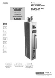
Instruktor<br />
900<br />
Veritas<br />
1000<br />
4000<br />
Veritas<br />
5000<br />
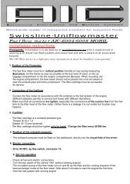
Fuel flow<br />
Master<br />
<strong>6000</strong><br />
Swissline<br />
FS<br />
BC 2022<br />
+<br />
Totalizer<br />
CE Zertifiziert<br />
EME geprüft<br />
Laut Euro-Norm<br />
95/54/CE<br />
CE certified<br />
EME Test according to<br />
95/54/CE directives<br />
Certifié CE<br />
Conforme aux tests<br />
EME suivant la<br />
directive 95/54/CE<br />
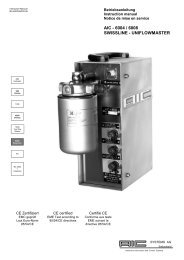
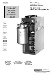
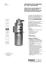
Instruction manual<br />
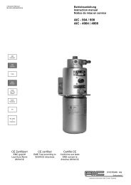
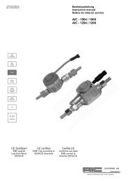
<strong>AIC</strong>-<strong>6000</strong> series<br />
Installation of circulation <strong>pump</strong><br />
SYSTEMS AG<br />
Switzerland<br />
Automotive Information and Control <strong>Systems</strong>
SAFETY FIRST<br />
The <strong>AIC</strong> 6004 or <strong>AIC</strong> 6008 meters can only be installed in order to measure any fuel flow.<br />
Other applications are not guaranteed by <strong>AIC</strong>.<br />
The meters shall be installed, connected, commissioned, operated and maintained under supervision of a qualified<br />
engine engineer, who is aware of all danger factors.<br />
Important<br />
While opening the <strong>AIC</strong>-<strong>6000</strong> meter make sure that fuel oil has been removed from it.<br />
Removing the existing <strong>pump</strong><br />
1st step<br />
Outflow side first (Fork wrench 14 mm + 17 mm)<br />
Unscrew at the outflow side the elbow pipe connector first.<br />
Maintain the <strong>pump</strong> side nut (DN 14) with the fork wrench, and<br />
unscrew the elbow nut (DN 17). As shown on the picture.<br />
2nd step<br />
Outflow side (Fork wrench 2 x17 mm)<br />
Unscrew at the outside flow side, the banjo connector.<br />
Maintain the <strong>pump</strong> side screw (DN 17) with the fork wrench, and<br />
unscrew the nut (DN 17). As shown on the picture.<br />
2<br />
fork wrench 14<br />
fork wrench 17<br />
fork wrench 17
3rd step<br />
Inflow side (Fork wrench 2 x 19 mm)<br />
Unscrew at the inside flow, the banjo bolt of the extension pipe. Maintain the<br />
extension pipe (DN 19) with the fork wrench, and unscrew the banjo bolt (DN<br />
19). As shown on the picture.<br />
4th step<br />
Disconnect the electrical connections<br />
Remove the <strong>pump</strong> from inside the stainless<br />
steel housing.<br />
Unscrew both electrical connector from the<br />
<strong>pump</strong><br />
Remove the protection<br />
caps, and disconnect the<br />
<strong>pump</strong><br />
5th step<br />
Inflow side (Fork wrench 22 mm + 19 mm)<br />
Unscrew at the inside flow, the extension pipe from the <strong>pump</strong>.<br />
Maintain the <strong>pump</strong> (DN 22) with the fork wrench, and unscrew the<br />
extension pipe (DN 19). As shown on the picture.<br />
3<br />
fork<br />
wrench<br />
19<br />
fork wrench 19<br />
fork<br />
wrench<br />
22
Mounting the new <strong>pump</strong><br />
Important<br />
• Make sure that while proceeding to the mounting of the <strong>pump</strong>, that no dirt is entering the <strong>pump</strong>.<br />
• While putting back the different bolts and nuts, please use always new copper washers.<br />
For mounting the new <strong>pump</strong> onto the <strong>AIC</strong>-<strong>6000</strong> meter, proceed from the step 5 to the step 1<br />
of the removing <strong>pump</strong> explanation.<br />
• Never exceed the following tightening torque :<br />
• Step 1 = 30 Nm<br />
• Step 2 = 30 Nm<br />
• Step 3 = 40 Nm<br />
• Step 4 = 5 Nm<br />
• Step 5 = 40 Nm<br />
Connection to the fuel hoses<br />
Important : all connections from tank, couplings and measuring instrument must be absolutely tight. When fuel<br />
leakage happens on suction side, no fuel leak can be seen, but engine malfunctions can be expected.<br />
After installation of the <strong>AIC</strong>-measuring-unit, the filter cartridge must be filled up with clean Diesel fuel (approx. 1 litre)<br />
before starting the engine.<br />
It is recommended to fill the filter via the external holes (inlet side of the filter) in order to filter the fuel brought in.<br />
Tighten up the filter cartridge by hand only.<br />
Do not fill Diesel this side<br />
4<br />
Fill Diesel this side
Bleeding / Venting<br />
Once the flow meter is mounted on the vehicle, meter, filter and piping system must be vented.<br />
Important notice:<br />
If the Diesel piping system is not vented correctly, an accurate measurement cannot be guaranteed.<br />
NB: the bleeding can be done by starting the engine then, it is not necessary to use the hand <strong>pump</strong> first!<br />
Bleeding / venting, step by step:<br />
On the flow meter, disconnect the return-line coming from the engine.<br />
Close the return-fitting on the flow meter with a cap-nut. The pipe connections need to be hermetically closed, to avoid<br />
air coming into the piping system during the bleeding / venting.<br />
Introduce the return-line into the filler-cap of the fuel-tank or into an other receptacle.<br />
Start the engine and run it in idling rpm.. Run the engine minimum 10 minutes as long as bubbles remain in the fuel.<br />
Stop the engine, remove cap nut on the return fitting, and connect the return-line to the flow meter<br />
Start again the engine and check the tightness after the test drive.<br />
Attention: engines with specific bleeding arrangement (fine filter for exp.), must be vented according to the<br />
engine manufacturer recommendations.<br />
Maintenance<br />
The maintenance of the <strong>AIC</strong> flow meters is limited to the exchange of the filter, to the periodical check of the fuel lines<br />
and to the tightness of the connectors.<br />
According to the fuel quality, we recommend to exchange the filter every 30 000 to 50 000 Km (20 000 to 35 000 Mi.)<br />
Filter characteristics<br />
Filter cartridge to be screwed on:<br />
0.75 to 1 litre<br />
Thread: M16 x 1.5<br />
Gasket diameter: 71 /62 mm<br />
Filter cartridge diameter: 93 mm<br />
Never blast compressed air into the flow meter !<br />
Example: HENGST H 17 WK 03 (L = 142 mm)<br />
MANN WK 940 / 5 (L = 142 mm)<br />
MANN WK 962 / 4 (L = 210 mm)<br />
HIFI FF 231 (L = 142 mm)<br />
HIFI FF 4070 (L = 210 mm)<br />
5
<strong>AIC</strong> Services Hotline: +41 79 212 28 31<br />
Doc. ref. <strong>BA</strong> <strong>6000</strong>/circ. <strong>pump</strong>/e/11.05<br />
Never blast compressed air into the flow meter !<br />
6<br />
<strong>AIC</strong> SYSTEMS USA<br />
2970 N. Stowell Ave.<br />
Milwaukee, WI 53211<br />
United States of America<br />
T/M +1 262 206 03 96<br />
aic-usa@wi.rr.com<br />
<strong>AIC</strong> SYSTEMS S.A.<br />
Postfach / P.O. Box 341<br />
Ringstrasse 9<br />
CH - 4123 Allschwil<br />
Switzerland<br />
T +41 61 841 84 39<br />
F +41 61 841 84 40<br />
M +41 79 212 28 31<br />
www.flowmeter-aic.com<br />
aic@bluewin.ch<br />
SYSTEMS AG<br />
Switzerland<br />
Automotive Information and Control <strong>Systems</strong>