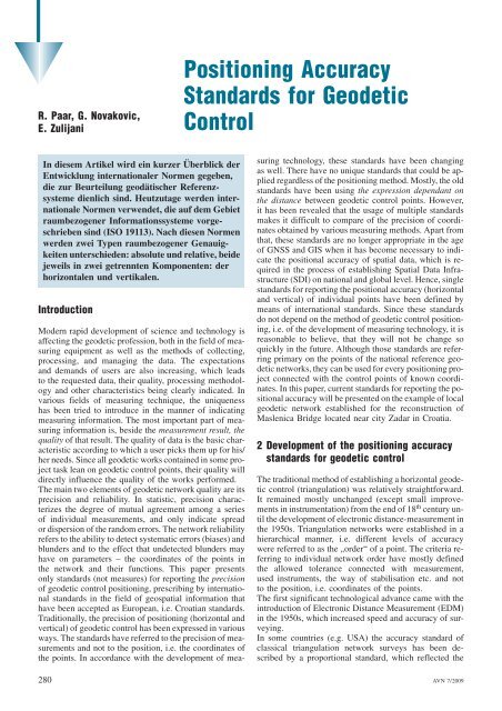
Positioning Accuracy Standards for Geodetic Control
Positioning Accuracy Standards for Geodetic Control
Positioning Accuracy Standards for Geodetic Control

Create successful ePaper yourself
Turn your PDF publications into a flip-book with our unique Google optimized e-Paper software.
R. Paar, G. Novakovic,<br />
E. Zulijani<br />
In diesem Artikel wird ein kurzer Überblick der<br />
Entwicklung internationaler Normen gegeben,<br />
die zur Beurteilung geodätischer Referenzsysteme<br />
dienlich sind. Heutzutage werden internationale<br />
Normen verwendet, die auf dem Gebiet<br />
raumbezogener In<strong>for</strong>mationssysteme vorgeschrieben<br />
sind (ISO 19113). Nach diesen Normen<br />
werden zwei Typen raumbezogener Genauigkeiten<br />
unterschieden: absolute und relative, beide<br />
jeweils in zwei getrennten Komponenten: der<br />
horizontalen und vertikalen.<br />
Introduction<br />
Modern rapid development of science and technology is<br />
affecting the geodetic profession, both in the field of measuring<br />
equipment as well as the methods of collecting,<br />
processing, and managing the data. The expectations<br />
and demands of users are also increasing, which leads<br />
to the requested data, their quality, processing methodology<br />
and other characteristics being clearly indicated. In<br />
various fields of measuring technique, the uniqueness<br />
has been tried to introduce in the manner of indicating<br />
measuring in<strong>for</strong>mation. The most important part of measuring<br />
in<strong>for</strong>mation is, beside the measurement result, the<br />
quality of that result. The quality of data is the basic characteristic<br />
according to which a user picks them up <strong>for</strong> his/<br />
her needs. Since all geodetic works contained in some project<br />
task lean on geodetic control points, their quality will<br />
directly influence the quality of the works per<strong>for</strong>med.<br />
The main two elements of geodetic network quality are its<br />
precision and reliability. In statistic, precision characterizes<br />
the degree of mutual agreement among a series<br />
of individual measurements, and only indicate spread<br />
or dispersion of the random errors. The network reliability<br />
refers to the ability to detect systematic errors (biases) and<br />
blunders and to the effect that undetected blunders may<br />
have on parameters – the coordinates of the points in<br />
the network and their functions. This paper presents<br />
only standards (not measures) <strong>for</strong> reporting the precision<br />
of geodetic control positioning, prescribing by international<br />
standards in the field of geospatial in<strong>for</strong>mation that<br />
have been accepted as European, i.e. Croatian standards.<br />
Traditionally, the precision of positioning (horizontal and<br />
vertical) of geodetic control has been expressed in various<br />
ways. The standards have referred to the precision of measurements<br />
and not to the position, i.e. the coordinates of<br />
the points. In accordance with the development of mea-<br />
<strong>Positioning</strong> <strong>Accuracy</strong><br />
<strong>Standards</strong> <strong>for</strong> <strong>Geodetic</strong><br />
<strong>Control</strong><br />
suring technology, these standards have been changing<br />
as well. There have no unique standards that could be applied<br />
regardless of the positioning method. Mostly, the old<br />
standards have been using the expression dependant on<br />
the distance between geodetic control points. However,<br />
it has been revealed that the usage of multiple standards<br />
makes it difficult to compare of the precision of coordinates<br />
obtained by various measuring methods. Apart from<br />
that, these standards are no longer appropriate in the age<br />
of GNSS and GIS when it has become necessary to indicate<br />
the positional accuracy of spatial data, which is required<br />
in the process of establishing Spatial Data Infrastructure<br />
(SDI) on national and global level. Hence, single<br />
standards <strong>for</strong> reporting the positional accuracy (horizontal<br />
and vertical) of individual points have been defined by<br />
means of international standards. Since these standards<br />
do not depend on the method of geodetic control positioning,<br />
i.e. of the development of measuring technology, it is<br />
reasonable to believe, that they will not be change so<br />
quickly in the future. Although those standards are referring<br />
primary on the points of the national reference geodetic<br />
networks, they can be used <strong>for</strong> every positioning project<br />
connected with the control points of known coordinates.<br />
In this paper, current standards <strong>for</strong> reporting the positional<br />
accuracy will be presented on the example of local<br />
geodetic network established <strong>for</strong> the reconstruction of<br />
Maslenica Bridge located near city Zadar in Croatia.<br />
2 Development of the positioning accuracy<br />
standards <strong>for</strong> geodetic control<br />
The traditional method of establishing a horizontal geodetic<br />
control (triangulation) was relatively straight<strong>for</strong>ward.<br />
It remained mostly unchanged (except small improvements<br />
in instrumentation) from the end of 18 th century until<br />
the development of electronic distance-measurement in<br />
the 1950s. Triangulation networks were established in a<br />
hierarchical manner, i.e. different levels of accuracy<br />
were referred to as the „order“ of a point. The criteria referring<br />
to individual network order have mostly defined<br />
the allowed tolerance connected with measurement,<br />
used instruments, the way of stabilisation etc. and not<br />
to the position, i.e. coordinates of the points.<br />
The first significant technological advance came with the<br />
introduction of Electronic Distance Measurement (EDM)<br />
in the 1950s, which increased speed and accuracy of surveying.<br />
In some countries (e.g. USA) the accuracy standard of<br />
classical triangulation network surveys has been described<br />
by a proportional standard, which reflected the<br />
280 AVN 7/2009
distance-dependant nature of terrestrial surveying error<br />
(e.g. it has been prescribed that the First-order network<br />
has got a minimum distance accuracy 1:100000. Distance<br />
accuracy is the ratio of the relative positional error of a<br />
pair of control points to the horizontal separation of those<br />
points). The distance accuracy pertains to all pairs of<br />
points. The worst distance accuracy (smallest denominator)<br />
is taken as the accuracy <strong>for</strong> classification (FGCC<br />
1984). Hence, the accuracy of coordinates of individual<br />
points in the network has not been determined, but the order<br />
of the entire network. The same concept was valid <strong>for</strong><br />
vertical networks. The accuracy standards have been referring<br />
to the accuracy in determining height differences<br />
(not to the bench mark heights) and they have been proportional<br />
to distance: <strong>for</strong> differential levelling directly<br />
proportional to square root of distance, and <strong>for</strong> trigonometric<br />
levelling directly proportional to distance between<br />
points.<br />
The second, more significant technological advance has<br />
been the development of Global <strong>Positioning</strong> System<br />
(GPS) – an order of magnitude more precise (<strong>for</strong> horizontal<br />
positioning) than the data obtained from earlier classical<br />
methods. The accuracy of GPS surveys, being less<br />
distance dependant requires different accuracy standards.<br />
Since the previous survey standards were not adequate <strong>for</strong><br />
classifying high precision GPS survey, a new system of<br />
classification has been adopted. In some countries, new<br />
network orders are introduced and new standards set<br />
that are valid only <strong>for</strong> GPS-positioning (e.g. USA, Australia).<br />
<strong>Accuracy</strong> standards <strong>for</strong> GPS are expressed in terms of<br />
maximum allowable base error and line-length error <strong>for</strong><br />
relative position (e.g. <strong>for</strong> B-order the allowed relative position<br />
of a single points as related to some other is<br />
8mm þ 1 ppm-minimum geometric accuracy standard<br />
at the 95 % confidence level, FGCC 1988). The network<br />
order has been determined, similarly as with triangulation,<br />
according to the baseline in the network that has the smallest<br />
relative accuracy. It must be emphasised that new, statistical<br />
concept <strong>for</strong> reporting the results at defined confidence<br />
level is applied here.<br />
The use of multiple standards created difficulty in comparing<br />
the accuracy of coordinate values obtained by different<br />
survey methods. So, the new methodology <strong>for</strong> reporting<br />
the accuracy of horizontal and vertical coordinate<br />
values has been introduced, which is independent of positioning<br />
methods. These criteria are contained in the standards<br />
referring to the field of geospatial in<strong>for</strong>mation.<br />
2.1 Standardisation of geospatial data<br />
There are various standard components <strong>for</strong> geodetic data<br />
(NGS 2002). One of the components refers to the quality<br />
standards. These are the accuracy standards and operational<br />
standards <strong>for</strong> data collection. The criteria <strong>for</strong> positioning<br />
accuracy reporting are prescribed by the standards<br />
ISO 19113, ISO 19114 and ISO 19115, that have been accepted<br />
as European, i.e. Croatian standards. ISO Standard<br />
19113: Geographic In<strong>for</strong>mation – Quality principles defines<br />
a data quality model and identifies Positional accuracy<br />
as one of a spatial data quality element with two sub<br />
elements: absolute or external accuracy and relative or<br />
R. Paar, G. Novakovic, E. Zulijani – <strong>Positioning</strong> <strong>Accuracy</strong> <strong>Standards</strong> <strong>for</strong> <strong>Geodetic</strong> <strong>Control</strong><br />
internal accuracy. They express the quantitative in<strong>for</strong>mation<br />
about data quality. Positional accuracy (absolute and<br />
relative) have to be reported <strong>for</strong> both horizontal and vertical<br />
component of position.<br />
Hence, when reporting the precision of geodetic control<br />
positioning, two types of precision should be reported<br />
in accordance with the mentioned standard: absolute<br />
and relative, both <strong>for</strong> horizontal coordinates and <strong>for</strong><br />
height. These types of precision should be clearly defined<br />
and their calculation explained.<br />
Here is a comment referring to terminology. This standard<br />
prescribes that absolute or relative accuracies are expressed<br />
quantitatively (associate a number). This is not<br />
in accordance with the definitions in Guide to the expression<br />
of uncertainty in measurement (ISO 1995). In Appendix<br />
D, article D.1.1.1 comment 2, is stated: Because „accuracy“<br />
is a qualitative concept, one should not use it<br />
quantitatively, that is, associate numbers with it; numbers<br />
should be associated with measures of uncertainty instead.<br />
Thus, one may write, „the standard uncertainty is 2 cm“<br />
but not „the accuracy is 2 cm.“<br />
Many countries, in their national accuracy standards <strong>for</strong><br />
geodetic control positioning, use different terms <strong>for</strong> reporting<br />
absolute and relative accuracies, but they refer<br />
to mentioned ISO standard. For example, in USA and Canada<br />
these terms are Network accuracy (absolute accuracy)<br />
and Local accuracy (relative accuracy). According<br />
to definitions in GUM (ISO 1995), much more appropriate<br />
are notation accepted in Australia: Positional uncertainty<br />
(absolute) and Local uncertainty (relative). In Hungary,<br />
the accepted terms are Positional accuracy (absolute)<br />
and Positional precision (relative) (INSPIRE 2004). In<br />
Croatia, these terms are not defined yet (Novaković<br />
2006), so in our paper we will use the terms accepted<br />
in Australia: Positional and Local uncertainty.<br />
3 Geospatial positional accuracy standards<br />
<strong>for</strong> geodetic control<br />
Using various statistical methods, it can be created many<br />
different position accuracy measures. The position is fundamentally<br />
three dimensional, but not everyone is interested<br />
in obtaining three-dimensional accuracy. One user<br />
might care about horizontal accuracy, another might<br />
want vertical. Thus, we must consider different 1-D, 2-<br />
D or 3-D accuracy measures (statistics). Statistics can<br />
have varying confidence levels and each of them has<br />
its certain importance <strong>for</strong> particular applications. Each<br />
of those measures provides an indication of the spread<br />
or dispersion of the set of estimates about their mean<br />
or expected value, reflecting the random error in the repeated<br />
measurements, so, in fact, they provide an indication<br />
of precision or repeatability.<br />
The most commonly used linear measures (1-D) are 1-r<br />
standard deviation (68.27 % probability) and 95 % Probability/Confidence<br />
(95 % probability), typical used <strong>for</strong> expressing<br />
the precision of vertical component of position.<br />
In 2-D case (horizontal components of position), commonly<br />
used measures are: 1-r Standard Error Circle<br />
(39 % probability), Circular Error Probable (CEP)<br />
AVN 7/2009 281
R. Paar, G. Novakovic, E. Zulijani – <strong>Positioning</strong> <strong>Accuracy</strong> <strong>Standards</strong> <strong>for</strong> <strong>Geodetic</strong> <strong>Control</strong><br />
(50 % probability), 95 % 2-D Positional Confidence Circle<br />
(95 % probability), 2-Dev. Root Mean Square<br />
(2DRMS) (95 – 98 % probability). In 3-D case, those measures<br />
are: 1-r Spherical Standard Error (19.9 % probability),<br />
Spherical Error Probable (SEP) (50 % probability),<br />
95 % 3-D Confidence Spheroid (95 % probability) and<br />
many others (EM 1110-1-1003, Diggelen 1998). GPS positional<br />
accuracies are normally estimate and report using<br />
root mean square (RMS) error statistic. The probability<br />
associated with rms depends on whether one is using<br />
rms in one, two, or three dimensions.<br />
According to ISO standards, the geospatial positional uncertainty<br />
shall be reported separately in two components:<br />
horizontal and vertical. Reporting standards are a circle<br />
<strong>for</strong> horizontal uncertainty and a linear value <strong>for</strong> vertical<br />
uncertainty, both at specified confidence level (FGDC<br />
1998, ICSM 2004) (fig. 1). It is accepted that the confidence<br />
level <strong>for</strong> reporting the uncertainty of geodetic control<br />
position is 95 %.<br />
Horizontal: The reporting standard in the horizontal component<br />
is the radius of a circle of uncertainty, such that<br />
true or theoretical location of the point falls within that<br />
circle, at the 95 % confidence level.<br />
Vertical: The reporting standard in the vertical component<br />
is a linear uncertainty value, such that true or theoretical<br />
location of the point falls within the sum of the positive<br />
and negative ranges of that linear uncertainty value, at the<br />
95 % confidence level.<br />
In Canada, instead of confidence circle, the uncertainty<br />
region is confidence ellipse and reporting standard is<br />
the values of the semi-major axes (GSD 1996).<br />
Since the Positional accuracy consists of two sub-elements:<br />
absolute and relative accuracy (ISO 19113), the<br />
quantitative indication of the quality of coordinates (horizontal<br />
and vertical) requires two criteria to be defined<br />
and indicated. These are:<br />
Positional Uncertainty of a control point is the value that<br />
represents the uncertainty in the coordinates of the control<br />
point with respect to the geodetic datum, at the 95 % confidence<br />
level.<br />
<strong>Geodetic</strong> datum is expressed by the geodetic value of<br />
the control points that define national reference system.<br />
For horizontal coordinates, the Positional uncertainty<br />
of a point is the radius of the 95 % confidence circle.<br />
For vertical coordinate, the Positional uncertainty of<br />
Fig. 1: <strong>Standards</strong> <strong>for</strong><br />
positional uncertainty<br />
a point is the 95 % confidence interval. Positional uncertainty<br />
measures how well coordinates approach an<br />
ideal, error-free datum. Positional Uncertainty can be<br />
computed <strong>for</strong> any positioning project that is connected<br />
to the national reference network.<br />
Local uncertainty of a control point is a value that represents<br />
the uncertainty in the coordinates of the control point<br />
relative to the coordinates of other directly connected, adjacent<br />
control points at the 95 % confidence level. The reported<br />
Local Uncertainty is an approximate average of the<br />
individual local uncertainty values between this control<br />
point and other observed control points used to establish<br />
the coordinate of the control point. Extremely high or low<br />
individual local uncertainties are not considered in computing<br />
the average Local uncertainty of a control point.<br />
For horizontal coordinate, the Local uncertainty of a<br />
point is computed using an average of the radius of<br />
the 95 % relative confidence circle, between the point<br />
and other adjacent points. For vertical coordinate,<br />
the Local accuracy of a point is computed using an average<br />
of the 95 % relative confidence intervals between<br />
a point and other adjacent points.<br />
Positional and local uncertainties are fundamentally similar<br />
concepts. Local uncertainty describes positional uncertainty<br />
between adjacent points, and Positional uncertainty<br />
describes the positional uncertainty between a point and<br />
the national reference network. Used together, it is possible<br />
to estimate uncertainties between points not directly<br />
measured, or compare positions determined from two separate<br />
surveys (TxDOT 2005).<br />
Additionally, the Positional and Local uncertainty may be<br />
classified by comparing the radius of the 95 % confidence<br />
circle <strong>for</strong> horizontal coordinate uncertainty, and the 95 %<br />
confidence interval <strong>for</strong> vertical uncertainty, against a set<br />
of standards (accuracy classes). Namely, in the process of<br />
establishing the National Spatial Data Infrastructure<br />
(NSDI), all spatial data (as well as geodetic control points)<br />
are classified into individual precision classes. In some<br />
countries, the organisations <strong>for</strong> standardisation or other<br />
authorized institutions have officially prescribed the classification<br />
into classes, as e.g.: USA – 13 classes (> 1mm<br />
– 10 m) (FGDC 1998), Australia – same as USA, Canada<br />
– 14 classes (1 cm–200 m) (GSD 1996), Mexico – 1 cm –<br />
500 m (HANSEN ALBITES 2005).<br />
3.1 Computation of the Positional and Local<br />
uncertainty of the geodetic control points<br />
The Positional and Local uncertainty (horizontal and vertical)<br />
of each point in the network can be computed using<br />
elements of a global variance-covariance matrix of the adjusted<br />
parameters (coordinates), produced from a least<br />
squares adjustment. This matrix contains the following in<strong>for</strong>mation:<br />
– standard deviations of the estimated parameters<br />
– correlations between the parameters<br />
– absolute or point error ellipses (or ellipsoids)<br />
– line or relative error ellipses (or ellipsoids).<br />
The global cofactor matrix of the coordinates can be partitioned<br />
into block sub-matrices representing the cofactor<br />
matrix <strong>for</strong> each station and the cofactor matrix between<br />
282 AVN 7/2009
pairs of stations. The elements of absolute and relative<br />
ellipses can be computed using elements of corresponding<br />
sub-matrices (KUANG 1996, PELZER 1985).<br />
3.1.1 Vertical coordinate uncertainty computation<br />
The statistic used to represent the Positional and Local<br />
uncertainty of the height of the point is the 95 % confidence<br />
interval (fig. 1).<br />
Positional uncertainty<br />
The standard deviation, derived from the covariance matrix<br />
of the estimated parameters, represents the one-sigma<br />
Positional uncertainty of the adjusted height at the point.<br />
The statistic used to represent the Positional uncertainty of<br />
the vertical coordinate (height) of the point is the 95 %<br />
confidence interval (fig. 1). To obtain the 95 % confidence<br />
interval, the standard deviation is scaled by 1.96.<br />
Local uncertainty<br />
Local uncertainty at the point is based upon an average of<br />
the individual local uncertainties (or relative uncertainties)<br />
between that point and other adjacent points. The<br />
standard deviation of the height difference between two<br />
points can be derived from the covariance matrix of the<br />
estimated parameters. To obtain the 95 % confidence interval,<br />
the standard deviation of the height difference is<br />
scaled by 1.96.<br />
3.1.2 Horizontal coordinate uncertainty computation<br />
The statistic used to represent the Positional and Local<br />
uncertainty of the horizontal coordinates of the point is<br />
the radius of the 95 % confidence circle (fig. 1). The radius<br />
of the 95 % confidence circle can be computed using the<br />
elements of standard error ellipse.<br />
The „absolute“ or „point“ error ellipse gives the confidence<br />
region of the coordinates of a single point with respect<br />
to the constraining stations. The „relative“ or „line“<br />
ellipses indicate the precision of any point in a network<br />
relative to another point in that network. The equations<br />
<strong>for</strong> computation the size and orientation of absolute<br />
and relative ellipses are well known and published in<br />
many textbooks and publications (e.g. PELZER 1985, CASP-<br />
ARY 2000, KUANG 1996, WOLF, GHILANI 1997). Thus, the<br />
Positional uncertainty of the point should be computed<br />
using absolute or point error ellipse, and Local uncertainty<br />
should be computed using line or relative error ellipses.<br />
Fig. 2: The 95 % confidence ellipse and circle<br />
R. Paar, G. Novakovic, E. Zulijani – <strong>Positioning</strong> <strong>Accuracy</strong> <strong>Standards</strong> <strong>for</strong> <strong>Geodetic</strong> <strong>Control</strong><br />
Positional uncertainty<br />
Once the standard (point) error ellipse is available, the radius<br />
r of the 95 % confidence circle (fig. 2) is approximated<br />
by (LEENHOUTS 1985, GSD 1996, ICSM 2004):<br />
r ¼ Kpa<br />
where<br />
Kp ¼ 1:960790 þ 0:004071 C þ 0:114276 C 2 þ 0:371625 C 3<br />
C ¼ b=a<br />
and<br />
a semi-major axis of the standard error ellipse<br />
b semi-minor axis of the standard error ellipse.<br />
It must be noted that the coefficients in the above expression<br />
are specific to the 95 % confidence level, so that the<br />
radius of the 95 % confidence circle is obtained directly.<br />
The radius of a 95 % circle of uncertainty is produced by<br />
many least squares adjustment software (e.g. Trimble Total<br />
<strong>Control</strong>).<br />
In Canada, instead of the confidence circle, the statistics<br />
<strong>for</strong> reporting the uncertainty of horizontal position is the<br />
95 % confidence ellipse (fig. 2). The standard ellipse representing<br />
the one-sigma Network accuracy (Positional<br />
uncertainty) of the adjusted horizontal coordinates at a<br />
point. To convert the standard ellipse to a 95 % confidence<br />
ellipse the computed values of a and b must be multiplied<br />
by the appropriate expansion factor (this factor is 2.45 <strong>for</strong><br />
adjustment with high degrees of freedom). The major<br />
semi-axes of the 95 % confidence ellipse represent the<br />
Network accuracy of a point (GSD 1996). It is not necessary<br />
directly connect control point to a national reference<br />
network to compute its Positional uncertainty. It is necessary<br />
that the survey be connected to existing control points<br />
with known Positional uncertainty values. Standard error<br />
ellipse used to calculate Positional uncertainty might be<br />
obtained by one of the following methods (ICSM 2004):<br />
– Rigorous least squares adjustment of all observations<br />
linking the point in question back to the national geodetic<br />
datum. This would only be done as part of a national<br />
adjustment, in which case the error ellipses <strong>for</strong> all<br />
points in the adjustment would be available.<br />
– A statistical combination of the chain of error ellipses<br />
obtained from each level of the adjustment process,<br />
down to the point in question.<br />
– By constraining the control in the local least square adjustment<br />
to the known error ellipse in terms of the national<br />
geodetic datum.<br />
Local uncertainty<br />
The Local uncertainty at the point is based upon an average<br />
of the individual local uncertainties (or relative uncertainties)<br />
between that point and other adjacent points. The<br />
calculation of Local Uncertainty is identical to the method<br />
<strong>for</strong> calculation Positional Uncertainty, except that error<br />
ellipse used is relative ellipse between the two points<br />
in question, or the average of those from the point in question<br />
to adjacent points in the network.<br />
AVN 7/2009 283
R. Paar, G. Novakovic, E. Zulijani – <strong>Positioning</strong> <strong>Accuracy</strong> <strong>Standards</strong> <strong>for</strong> <strong>Geodetic</strong> <strong>Control</strong><br />
3.2 Example of calculating Positional and Local<br />
uncertainty of geodetic control points<br />
Although the illustrated standards <strong>for</strong> reporting the uncertainty<br />
of coordinates are mostly founded <strong>for</strong> the points of<br />
national reference geodetic networks, they can be used <strong>for</strong><br />
every positioning project connected with the reference<br />
control points.<br />
For many engineering applications, the precision of positioning<br />
of two points relative to each other (local uncertainty)<br />
is of much more importance that their precise positioning<br />
in a coordinate system (Positional uncertainty).<br />
The point ellipses may not indicate the relativity between<br />
points if there is high correlation between them. In a minimally<br />
constrained or constrained adjustment, there are different<br />
point ellipses <strong>for</strong> each of the points, depending on<br />
the choice of the fixed point(s), i.e. the absolute error<br />
ellipses will vary with the choice of origin of a network.<br />
However, in the minimally constrained adjustment, the<br />
relative ellipses are practically fixed. The relative error<br />
ellipses are unaffected by the choice of origin.<br />
Computation of the Positional and Local uncertainty of<br />
horizontal coordinates will be shown on the geodetic network<br />
established <strong>for</strong> the reconstruction of old Maslenica<br />
Bridge. The old Maslenica Bridge was demolished 1991,<br />
during Croatian War of Independence (fig. 3), and its reconstruction<br />
has been finished in 2006.<br />
The new Maslenica Bridge (fig. 4) is 315.30 m long, according<br />
to weight assignment, it is arch bridge, and it is<br />
Fig. 3: Destroyed Maslenica Bridge<br />
Fig. 4: Reconstructed Maslenica Bridge Fig. 5: Stabilization of the control points<br />
Fig. 6: Configuration of the geodetic control of Maslenica<br />
Bridge<br />
284 AVN 7/2009
Fig. 7: The 95 % point and relative ellipses and confidence<br />
circles<br />
Tab. 1: Positional and Local uncertainty of horizontal<br />
coordinates (95 %)<br />
Station Type To Station Horizontal uncertainties<br />
(mm)<br />
1 Positional 13.8<br />
Local 2 0.7<br />
Local 3 0.9<br />
Local 4 1.2<br />
Local average 0.93<br />
2 Positional 12.9<br />
Local 1 0.7<br />
Local 3 0.9<br />
Local 4 1.2<br />
Local DT13 0.6<br />
Local average 0.85<br />
3 Positional 13.8<br />
Local 1 0.9<br />
Local 2 0.9<br />
Local 4 1.2<br />
Local DT55 0.7<br />
Local average 0.93<br />
4 Positional 16.4<br />
Local 1 1.2<br />
Local 2 1.2<br />
Local 3 1.2<br />
Local average 1.2<br />
R. Paar, G. Novakovic, E. Zulijani – <strong>Positioning</strong> <strong>Accuracy</strong> <strong>Standards</strong> <strong>for</strong> <strong>Geodetic</strong> <strong>Control</strong><br />
made of steel. The bridge is designed <strong>for</strong> road and pedestrian<br />
traffic. According to span dimension (100 – 300 m),<br />
this is a big bridge. There are two traffic and two pedestrian<br />
tracks, which are all together 10.5 m wide.<br />
For the bridge reconstruction, the local geodetic network<br />
was established. The network consists of six points<br />
(fig. 6), monumented as shown on figure 5. For surveying<br />
the network, Fast Static GPS method, in combination with<br />
triangulation and trilateration, was used. The heights were<br />
determined by precise differential levelling.<br />
In this paper, calculation of Positional and Local uncertainty<br />
of horizontal coordinates using only terrestrial<br />
data is presented. The survey was connected to existing<br />
control points DT13 and DT55 (fig. 7). During adjustment,<br />
datum values are weighted using one-sigma their Positional<br />
uncertainty. At first, results of a minimally constrained,<br />
least squares adjustment of the survey measurements<br />
are examined (using statistical tests) to ensure correct<br />
weighting of the observations and freedom of outlying<br />
observations (examination of the reliability). After<br />
that, Positional and Local uncertainties of the new points<br />
were determined (table 1).<br />
Point error ellipses were used to compute error circle radii<br />
<strong>for</strong> Positional uncertainty. Relative error ellipse values<br />
were used to compute error circle radii <strong>for</strong> Local uncertainty.<br />
The evaluation has been made from each point to<br />
all adjacent points regardless of the direct connections in<br />
the network.<br />
The calculation of Positional and Local Uncertainty of<br />
heights is identical to the method <strong>for</strong> calculation these values<br />
<strong>for</strong> horizontal coordinates, except that in stead 95 %<br />
confidence circles the 95 % confidence intervals are used.<br />
From the results, we can conclude that high absolute and<br />
relative precision of the established network were obtained.<br />
4 Conclusion<br />
The quality of geodetic control, which all works within<br />
some project are based on, influences directly the successful<br />
implementation of that project. The positioning precision,<br />
as one of the most important component of geodetic<br />
control quality, has been expressed in various ways depending<br />
on the positioning method. The standards have<br />
been referring to the precision of observations, and not<br />
to the coordinates of geodetic control points. These standards<br />
reflected the distance-dependant nature of terrestrial<br />
surveying error: Triangulation and Traverse – directly<br />
proportional to distance between points; differential levelling<br />
– directly proportional to square root of the distance;<br />
trigonometric levelling – directly proportional to distance<br />
between points and GPS – horizontal: base error<br />
þ directly proportional to distance between points<br />
at 95 % confidence level, vertical: directly proportional<br />
to distance between points.<br />
Since the usage of multiple standards makes the comparison<br />
of the accuracy of the points coordinates obtained<br />
with various measuring methods very difficult, unique<br />
standards have been established <strong>for</strong> expressing the spatial<br />
data accuracy, and they are defined by international stan-<br />
AVN 7/2009 285
R. Paar, G. Novakovic, E. Zulijani – <strong>Positioning</strong> <strong>Accuracy</strong> <strong>Standards</strong> <strong>for</strong> <strong>Geodetic</strong> <strong>Control</strong><br />
dards. There is only one type of data used that the standards<br />
refer to, i.e. the coordinates of geodetic control<br />
points.<br />
New standards present a significant change in expressing<br />
the positioning accuracy of geodetic control points. They<br />
describe general classification that is based on the accuracy<br />
of spatial coordinates expressing at the defined confidence<br />
level. Principal changes included requirements to<br />
report numeric uncertainty values: a composite statistic<br />
<strong>for</strong> horizontal uncertainty (radius of confidence circle<br />
r) instead of individual component of uncertainty (sx,<br />
sy), and standard deviation <strong>for</strong> vertical uncertainty.<br />
Various data users have various demands with regard to<br />
the quality of these data, and hence, two types of standards<br />
have been defined <strong>for</strong> the geodetic control points: Positional<br />
and Local uncertainty, which are compatible with<br />
the quantities Absolute <strong>Positioning</strong> <strong>Accuracy</strong> and Relative<br />
Positional <strong>Accuracy</strong> prescribed by ISO 19113. These<br />
quantities might be applied to positions determined by<br />
any means, but <strong>for</strong> geodetic surveying, they are computed<br />
from the appropriate error ellipses (<strong>for</strong> horizontal position)<br />
and standard deviations (<strong>for</strong> heights).<br />
Positional and local uncertainties are simple indicators of<br />
the quality of position. For horizontal coordinates of the<br />
point, the uncertainty is the radius of a „circle of error“<br />
derived using a 95 % confidence level. For height, the uncertainty<br />
is a linear interval, using 95 % confidence level.<br />
Positional uncertainty is global or absolute, computed<br />
with respect to the reference frame or datum and Local<br />
uncertainty is computed with respect to adjacent points<br />
within the same data set or source.<br />
Although the illustrated standards <strong>for</strong> reporting the uncertainty<br />
of coordinates are mostly founded <strong>for</strong> the points of<br />
national reference geodetic networks, they can be used <strong>for</strong><br />
every positioning project connected with the reference<br />
control points. For engineering projects, it is more important<br />
to obtain estimates of the precision of the relative positions<br />
(local uncertainty) of two points, rather than of<br />
their absolute positions (positional uncertainty).<br />
Since the current standards do not refer to the quality of<br />
surveying being constantly changed along with the development<br />
of technology, this means of reporting the positioning<br />
quality will not be changed so soon.<br />
References<br />
[1] Anonym. (2003): NAVSTAR Global <strong>Positioning</strong> System<br />
Surveying (EM 1110-1-1003), US Army Corps of Engineers,<br />
Washington, DC<br />
[2] CASPARY, W. F. (2000): Concepts of Network and De<strong>for</strong>mation<br />
Analysis, School of Surveying, The University of<br />
New South Wales, Kensington<br />
[3] Country report on SDI, INSPIRE initiative. (2004): Spatial<br />
Data Infrastructure in Hungary<br />
[4] DIGGELEN, F. (1998): GPS <strong>Accuracy</strong>: Lies, Damn Lies,<br />
and Statistics, GPS World, Nov. 1998<br />
[5] FGCC (Federal <strong>Geodetic</strong> <strong>Control</strong> Committee). (1984):<br />
<strong>Standards</strong> and Specifications <strong>for</strong> <strong>Geodetic</strong> <strong>Control</strong> Networks,<br />
Silver Spring, Maryland, National <strong>Geodetic</strong> Survey,<br />
National Oceanic and Atmospheric Administration<br />
[6] FGCC (Federal <strong>Geodetic</strong> <strong>Control</strong> Committee). (1988):<br />
Geometric <strong>Geodetic</strong> <strong>Accuracy</strong> <strong>Standards</strong> and Specifica-<br />
tions <strong>for</strong> Using GPS Relative <strong>Positioning</strong> Technique, Version<br />
5.0, reprinted with corrections 1989, Silver Spring,<br />
Maryland, National <strong>Geodetic</strong> Survey, National Oceanic<br />
and Atmospheric Administration<br />
[7] FGDC (Federal Geographic Data Committee). (1998):<br />
Geospatial <strong>Positioning</strong> <strong>Accuracy</strong> <strong>Standards</strong>, Part 2, <strong>Standards</strong><br />
<strong>for</strong> <strong>Geodetic</strong> Networks, FGDC-STD-007.2-1998.<br />
Washington<br />
[8] GSD (<strong>Geodetic</strong> Survey Division). (1996): <strong>Accuracy</strong><br />
<strong>Standards</strong> <strong>for</strong> <strong>Positioning</strong>, Version 1.0, Ottawa, Canada,<br />
Natural Resources Canada<br />
[9] HANSEN ALBITES, D. A. (2005): Geodesy as a Fundamental<br />
Data Set in the Mexican SDI, FIG Working Week<br />
2005 and GSDI-8, Cairo, Egypt<br />
[10] ICSM (Inter-Governmental Committee on Surveying and<br />
Mapping). (2004): <strong>Standards</strong> and Practices <strong>for</strong> <strong>Control</strong><br />
Surveys (SP1), version 1.6, Australia<br />
[11] ISO (1995): Guide to the expression of uncertainty in<br />
measurement (GUM)<br />
[12] ISO/TC 211: ISO Standard 19113:2002 Geographic In<strong>for</strong>mation<br />
– Quality principles. (HRN EN ISO<br />
19113:2005)<br />
[13] KUANG, S. (1996): <strong>Geodetic</strong> Network Analysis and Optimal<br />
Design: Concepts and Applications, Ann Arbor<br />
Press, Inc., Chelsea, Michigan<br />
[14] LEENHOUTS, P. P. (1985): On the computation of Bi-Normal<br />
Radial Error, NAVIGATION: Journal of the Institut<br />
of Navigation, Vol. 32, No. 1, pp. 16–28<br />
[15] NGS (National <strong>Geodetic</strong> Survey) (2002): The Contribution<br />
of <strong>Geodetic</strong> data to the National Spatial Data Infrastructure,<br />
USA<br />
[16] NOVAKOVIĆ, G. (2006): Guidelines <strong>for</strong> development the<br />
Book of rules of technical standards <strong>for</strong> geodetic control,<br />
project <strong>for</strong> State <strong>Geodetic</strong> Administration Republic of<br />
Croatia, Zagreb<br />
[17] PELZER, H. (1985): Geodätische Netze in Landes- und Ingenieurvermessung<br />
II, Konrad Wittwer, Stuttgart<br />
[18] TxDOT (Texas Department of Transportation). (2005):<br />
GPS User’s Manual, Committee on Surveying<br />
[19] WOLF, P. R.; GHILANI, C. D. (1997): Adjustment computations<br />
– Statistics and least squares in surveying and<br />
GIS, John Wiley & Sons, New York<br />
Addresses of the autors:<br />
Prof. Dr. sc. GORANA NOVAKOVIĆ, University of Zagreb,<br />
Faculty of Geodesy, Kaciceva 26, 10000 Zagreb, Croatia,<br />
Tel. þ 3 85-(1)-46 39-3 07, Fax þ 3 85-(1)-46 39-2 22.<br />
gorana.novakovic@geof.hr<br />
MSc. RINALDO PAAR, University of Zagreb, Faculty of<br />
Geodesy, Kaciceva 26, 10000 Zagreb, Croatia, Tel.<br />
þ 3 85-(1)-46 39-3 71, Fax þ 3 85-(1)-46 39-2 22.<br />
rpaar@geof.hr<br />
EMILI ZULIJANI, Univ.-Dipl. Ing., Geofoto d.o.o., Buzinski<br />
prilaz 28, 10010 Zagreb, Croatia<br />
286 AVN 7/2009
Abstract<br />
Since the geodetic control points are the base (framework) <strong>for</strong> all surveying activities, the quality of these activities will<br />
directly depend of the quality (accuracy) of geodetic control. Traditionally, the accuracy standards <strong>for</strong> geodetic control<br />
positioning were related to the precision of observations, and not to the result, i.e. to the coordinates of geodetic control<br />
points. In the application of various positioning methods there were different standards used, which often made the<br />
comparison of measurement result quality impossible. Beside that, such standards are no longer adequate in the age of<br />
GNSS and GIS. The establishment of highly precise spatial reference system at the global and at the national level, and also<br />
great advance in achieving positioning precision referring to that system, have entailed new standards <strong>for</strong> reporting the<br />
positional accuracy of geodetic control. Current standards are related to the spatial position (coordinates) of geodetic<br />
control being independent of positioning methods or the survey instruments used. The paper presents these common<br />
standards <strong>for</strong> reporting the precision of positioning geodetic control points (horizontal and vertical) prescribed by<br />
international standards in the field of geospatial in<strong>for</strong>mation that have been accepted as European, i.e. Croatian standards<br />
(ISO 19113). In this paper, current standards <strong>for</strong> reporting the positional accuracy will be presented on the example of local<br />
geodetic network established <strong>for</strong> the reconstruction of Maslenica Bridge located near city Zadar in Croatia.<br />
Zusammenfassung<br />
Festpunkte bilden den Rahmen aller Vermessungsarbeiten, so dass die Qualität (Genauigkeit) des Referenzsystems direkt<br />
die Ergebnisse der Vermessungen beeinflusst. Die Qualität des Festpunktnetzes wird angegeben durch die Präzision<br />
und durch die Zuverlässigkeit. In diesem Beitrag werden die Normen angesprochen, die für die Bestimmung der<br />
Positionspräzision der Festpunkte relevant sind.<br />
Die Genauigkeitsangaben für das geodätische Referenzsystem sind traditionell mit der Präzision der Beobachtungen<br />
verbunden, und nicht mit dem Resultat, bzw. den Koordinaten der Festpunkte. Bei der Anwendung verschiedener<br />
Messmethoden wurden unterschiedliche Normen benutzt, die den Vergleich der Qualität der Messresultate unmöglich<br />
machen. Außerdem sind in der Zeit von GNSS und GIS derartige Normen nicht mehr relevant. Die Festlegung von<br />
hochpräzisen Raumbezugssystemen auf globaler und nationaler Ebene, wie auch die Entwicklung von hochpräzisen<br />
Verfahren der Positionsbestimmung er<strong>for</strong>dern die Bereitstellung neuer Normen. Jetzige Normen beziehen sich auf die<br />
Raumposition (Koordinaten) des geodätischen Referenzsystems. Der Beitrag stellt die internationalen Normen für die<br />
Bestimmung der Präzision der Festpunkte dar (horizontale und vertikale), die auf dem Gebiet der raumbezogenen<br />
In<strong>for</strong>mationssysteme vorgeschrieben sind und von europäischen bzw. kroatischen Normen übernommen worden sind<br />
(ISO 19113). In diesem Beitrag werden die derzeitigen Normen für die Bestimmung der Positionsgenauigkeit dargestellt,<br />
und zwar anhand eines Beispiels eines lokalen geodätischen Netzes, das für die Rekonstruktion der Maslenica-Brücke<br />
neben der Stadt Zadar in Kroatien geschaffen worden ist.<br />
Workshop „Basiswissen GDI“ vom 7. bis 11. September 2009<br />
an der Fachhochschule Frankfurt am Main<br />
Der fünftägige Workshop<br />
Basiswissen GDI ist ein<br />
Grundkurs für Personen, die<br />
in ihrem Berufsumfeld mit<br />
dem breiten Spektrum von<br />
Geodateninfrastrukturen in<br />
Berührung kommen. Das Angebot<br />
richtet sich insbesondere<br />
an Mitarbeiter der öffentlichen<br />
Verwaltung sowie<br />
Ingenieur- und Planungsbüros,<br />
die unter anderem durch<br />
die INSPIRE-Richtlinie animiert<br />
sind, sich mit den Möglichkeiten<br />
und Zielen einer<br />
R. Paar, G. Novakovic, E. Zulijani – <strong>Positioning</strong> <strong>Accuracy</strong> <strong>Standards</strong> <strong>for</strong> <strong>Geodetic</strong> <strong>Control</strong><br />
Geodateninfrastruktur vertraut<br />
zu machen.<br />
Der Workshop setzt keinerlei<br />
Vorwissen im Bereich der<br />
Geodateninfrastrukturen voraus,<br />
jedoch sollten die Teilnehmer<br />
Grundkenntnisse in<br />
der Anwendung von Geoin<strong>for</strong>mationssystemen<br />
sowie<br />
der Behandlung von Geodaten<br />
mitbringen. Der Workshop<br />
findet an fünf aufeinander<br />
folgenden Tagen statt,<br />
wobei jeder Tag ein für sich<br />
eigenes Themengebiet be-<br />
handelt und getrennt gebucht<br />
werden kann. In praxisnahen<br />
Übungen werden Anwendungen<br />
und Dienste einer GDI<br />
selbständig erlernt und somit<br />
die vorher gelegten theoretischen<br />
Grundlagen vertieft.<br />
Um dem Charakter eines<br />
Workshops gerecht zu werden,<br />
ist ausreichend Zeit vorgesehen<br />
Fragen der Teilnehmer<br />
zu Anwendungen und<br />
Entwicklungen im Kontext<br />
einer GDI zu beantworten<br />
oder zu diskutieren. Wegen<br />
ANKÜNDIGUNGEN<br />
. . . . . . . . . . . . . .<br />
des hohen Praxisanteils ist<br />
die Teilnehmeranzahl auf<br />
maximal 20 Personen pro<br />
Tag begrenzt.<br />
Dieser Workshop ist eine Gemeinschaftsveranstaltung<br />
des Instituts für Kommunale<br />
Geoin<strong>for</strong>mationssysteme e.V.<br />
(IKGIS) und der Fachhochschule<br />
Frankfurt am Main.<br />
Weitere In<strong>for</strong>mationen:<br />
www.gdi-testplatt<strong>for</strong>m.de<br />
bzw. www.ikgis.de<br />
AVN 7/2009 287