∫ ∫ ∫
∫ ∫ ∫
∫ ∫ ∫

You also want an ePaper? Increase the reach of your titles
YUMPU automatically turns print PDFs into web optimized ePapers that Google loves.
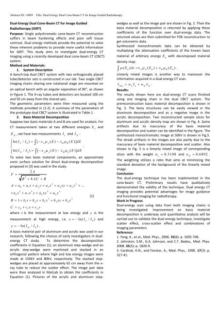
Abstract ID: 14889 Title: Dual-Energy Dual Cone-Beam CT for Image Guided Radiotherapy<br />
Dual-Energy Dual Cone-Beam CT for Image Guided<br />
Radiotherapy (IGRT)<br />
Purpose: Single polychromatic cone-beam CT reconstruction<br />
suffers in beam hardening effects and poor soft tissue<br />
contrast. Dual energy methods provide the potential to solve<br />
these inherent problems to provide more useful information<br />
for IGRT. This study aims to investigate dual-energy CT<br />
imaging using a recently developed dual cone-beam CT (CBCT)<br />
system.<br />
Method and Materials:<br />
1. System Description<br />
A bench-top dual CBCT system with two orthogonally placed<br />
tube/detector sets is constructed in our lab. Two single CBCT<br />
imaging chains sharing one rotational stage are mounted on<br />
an optical bench with an angular separation of 90°, as shown<br />
in Figure 1. The X-ray tubes and detectors are located 100 cm<br />
and 50 cm away from the shared axis.<br />
The geometric parameters were then measured using the<br />
methods provided in [1-2]. A summary of the parameters of<br />
the prototype dual CBCT system is illustrated in Table 1.<br />
2. Basis Material Decomposition<br />
Suppose two basis materials A and B are used for analysis. For<br />
CT measurement taken at two different energies E and L<br />
E , we have two measurements I and I :<br />
H<br />
L<br />
H<br />
ln( I / I ) [ x ( E ) x ( E )] dE<br />
L 0 A A B B<br />
<br />
.<br />
ln(<br />
I / I ) [ x ( E ) x ( E )] dE<br />
H 0<br />
A A B B<br />
<br />
To solve two basis material components, an approximate<br />
conic surface solution for direct dual-energy decomposition<br />
proposed in [3] was used in the study.<br />
2 A<br />
F <br />
2<br />
B 4 AC B<br />
2 2<br />
0 1 2 3 4 5<br />
A a a x a y a x a xy a y ...<br />
3 2 2 3<br />
6 7 8 9<br />
a x a x y a xy a y<br />
2 2<br />
1 2 3 4 5<br />
B 1 b x b y b x b xy b y<br />
C c c x c y<br />
0 1 2<br />
where x is the measurement at low energy and y is the<br />
measurement at high energy, i.e. x ln( I / I ) and<br />
L 0<br />
y ln( I / I ) .<br />
H<br />
0<br />
A basis material pair of aluminum and acrylic was used in our<br />
research, following the choices of early investigators in dualenergy<br />
CT study. To determine the decomposition<br />
coefficients in Equation (1), an aluminum step-wedge and an<br />
acrylic step-wedge were machined and stacked in an<br />
orthogonal pattern where high and low energy images were<br />
made at 150kV and 80kV, respectively. The stacked stepwedges<br />
are placed at approximately 65 cm away from the xray<br />
tube to reduce the scatter effect. The image pair data<br />
were then analyzed in MatLab to obtain the coefficients in<br />
Equation (1). Pictures of the acrylic and aluminum step-<br />
(1)<br />
wedges as well as the image pair are shown in Fig. 2. Then the<br />
basis material decomposition is returned by applying these<br />
coefficients of the function over dual-energy data. The<br />
returned values are then submitted for FDK reconstruction to<br />
get volumetric data.<br />
Synthesized monochromatic data can be obtained by<br />
multiplying the attenuation coefficients of the known basis<br />
material of arbitrary energy E with decomposed material<br />
0<br />
density map:<br />
<br />
( E ) ds x( E ) x ( E ) .<br />
0 A A 0 B B 0<br />
Linearly mixed images is another way to maneuver the<br />
information acquired in a dual-energy CT scan.<br />
I w I w I .<br />
Mix L L H H<br />
Results:<br />
The results shown here are dual-energy CT scans finished<br />
using one imaging chain in the dual CBCT system. The<br />
prereconstruction basis material decomposition is shown in<br />
Fig. 3. The bony structures can be easily viewed in the<br />
aluminum decomposition and as a negative image in the<br />
acrylic decomposition. Two reconstructed sample slices for<br />
aluminum and acrylic density map are shown in Fig. 4. Some<br />
artifacts due to inaccuracy of the basis material<br />
decomposition and scatter can be identified in the figure. The<br />
synthesized monochromatic image at 50kV is shown in Fig.5.<br />
The streak artifacts in the images are also partly due to the<br />
inaccuracy of basis material decomposition and scatter. Also<br />
shown in Fig. 5 is a linearly mixed image of corresponding<br />
slices with the weight w 0.3108 and w 0.6892 .<br />
L<br />
H<br />
The weighting utilizes a ratio that aims at minimizing the<br />
standard deviation of the background of the linearly mixed<br />
image.<br />
Conclusion<br />
The dual-energy technique has been implemented in the<br />
cone-beam CT. Preliminary results have qualitatively<br />
demonstrated the validity of the technique. Dual energy CT<br />
imaging provides potential advantages for image guidance<br />
and functional imaging for radiotherapy.<br />
Work in Progress<br />
Dual-energy scan using data from both imaging chains is<br />
being investigated. Improvement on basis material<br />
decomposition is underway and quantitative analysis will be<br />
carried out to validate the dual-energy technique, investigate<br />
scatter effect, cross-scatter effect and combinations of<br />
imaging parameters.<br />
Reference:<br />
1. Yang, K., et al., Med. Phys., 2006. 33(6): p. 1695-706.<br />
2. Johnston, S.M., G.A. Johnson, and C.T. Badea,. Med. Phys.<br />
2008. 35(5): p. 1820-9.<br />
3. Cardinal, H.N., and Fenster, A., Med. Phys., 1990. 17(3): p.<br />
327-41.
Abstract ID: 14889 Title: Dual-Energy Dual Cone-Beam CT for Image Guided Radiotherapy<br />
Figure 1. Picture of the dual cone-beam CT in the study.<br />
TABLE I. Summary of characteristics of the<br />
prototype dual CBCT system<br />
Dual CBCT Characteristics Values<br />
Acquisition Geometry<br />
Subsystem 1:<br />
Source-axis distance 99.9cm<br />
Source-imager distance 150.0cm<br />
Subsystem 2:<br />
Source-axis distance 100.0 cm<br />
Source-imager distance 150.2cm<br />
Cone Angle ~ 9.5<br />
Field of View 26.7 cm<br />
Angular Separation (measured) 90.6<br />
X-ray Beam<br />
Beam Energy (Maximal) 150 kV<br />
Exit Filtration 0.7 mm Al<br />
Flat Panel Detectors<br />
Manufacture and Model Varian Paxscan® 4030CB<br />
Pixel Matrix 2048 x 1536<br />
Pixel Pitch 194 μm<br />
Effective Area 397 mm x 298mm<br />
Limit Resolution 2.58 lp/mm @ 7.5 FPS (1x1)<br />
1.29 lp/mm @ 30 FPS (2x2)<br />
Conversion Screen Integral columnar CsI:Tl<br />
Receptor Type Amorphous Silicon<br />
Energy Range 40-150kVp<br />
Acquisition Procedure<br />
Number of Projections 360<br />
Angular Increment 1<br />
Rotational Speed 2/s<br />
Reconstruction Parameters<br />
Reconstruction matrix 512x512x160<br />
Voxel Dimension 0.488 mm x 0.488 mm x1 mm<br />
Figure 2. Pictures of the step-wedges and the image pair.<br />
Figure 3. Prereconstruction basis material<br />
decomposition.<br />
Figure 4. Reconstructed slices of basis material<br />
decomposition<br />
Figure 5. Synthesized monochromatic images and<br />
linearly mixed images.