INTEGRAL+ POSIGAM+ or MODUGAM+ - Fluid Control Services
INTEGRAL+ POSIGAM+ or MODUGAM+ - Fluid Control Services
INTEGRAL+ POSIGAM+ or MODUGAM+ - Fluid Control Services

Create successful ePaper yourself
Turn your PDF publications into a flip-book with our unique Google optimized e-Paper software.
NR1088A QXD Rev D<br />
Commissioning instructions f<strong>or</strong> f<strong>or</strong><br />
<strong>INTEGRAL+</strong><br />
control control<br />
and<br />
<strong>POSIGAM+</strong> <strong>or</strong> <strong>MODUGAM+</strong><br />
positioner<br />
L. BERNARD s.a.<br />
4 rue d'Arsonval - BP 91 - 95505 GONESSE CEDEX (FRANCE)<br />
Tél : (33).01.34.07.71.00 - Fax : (33).01.34.07.71.01 - E-mail : mail @ bernard-actuat<strong>or</strong>s.com
SUMMARY<br />
FEATURES . . . . . . . . . . . . . . . . . . . . . . . . . . . . . . . . . . . . . . . . . . . . . . . . . . . . . . . . . . . . . . . . . . . . .1<br />
1. INTRODUCTION . . . . . . . . . . . . . . . . . . . . . . . . . . . . . . . . . . . . . . . . . . . . . . . . . . . . . . . . . . . . . . . .2<br />
2. CONFIGURATION . . . . . . . . . . . . . . . . . . . . . . . . . . . . . . . . . . . . . . . . . . . . . . . . . . . . . . . . . . . . . . .2<br />
3. POWER SUPPLY . . . . . . . . . . . . . . . . . . . . . . . . . . . . . . . . . . . . . . . . . . . . . . . . . . . . . . . . . . . . . . .2<br />
3.1. ACTUATOR POWER SUPPLY . . . . . . . . . . . . . . . . . . . . . . . . . . . . . . . . . . . . . . . . . . . . . . . .2<br />
3.2. OUTPUT POWER SUPPLY . . . . . . . . . . . . . . . . . . . . . . . . . . . . . . . . . . . . . . . . . . . . . . . . . .2<br />
4. ACTUATOR OPERATION . . . . . . . . . . . . . . . . . . . . . . . . . . . . . . . . . . . . . . . . . . . . . . . . . . . . . . . . .3<br />
4.1 DIRECTION OF ROTATION . . . . . . . . . . . . . . . . . . . . . . . . . . . . . . . . . . . . . . . . . . . . . . . . . .3<br />
4.2 CLOSING TYPE . . . . . . . . . . . . . . . . . . . . . . . . . . . . . . . . . . . . . . . . . . . . . . . . . . . . . . . . . .3<br />
4.3 BY-PASS OF OPEN TORQUE SWITCH WHEN<br />
STARTING TO OPEN FROM CLOSED POSITION . . . . . . . . . . . . . . . . . . . . . . . . . . . . . . . . .3<br />
4.4 ROTATION REVERSE RELAY . . . . . . . . . . . . . . . . . . . . . . . . . . . . . . . . . . . . . . . . . . . . . . . .4<br />
5. REMOTE CONTROL . . . . . . . . . . . . . . . . . . . . . . . . . . . . . . . . . . . . . . . . . . . . . . . . . . . . . . . . . . . . .4<br />
5.1 DRY CONTACTS CONTROL . . . . . . . . . . . . . . . . . . . . . . . . . . . . . . . . . . . . . . . . . . . . . . . . .4<br />
5.2 VOLTAGE CONTROL . . . . . . . . . . . . . . . . . . . . . . . . . . . . . . . . . . . . . . . . . . . . . . . . . . . . . . .4<br />
5.3 SINGLE DRY CONTACT CONTROL . . . . . . . . . . . . . . . . . . . . . . . . . . . . . . . . . . . . . . . . . . .5<br />
5.4 PRIORITY TO OPEN OR TO CLOSE . . . . . . . . . . . . . . . . . . . . . . . . . . . . . . . . . . . . . . . . . . .5<br />
5.5 EMERGENCY CONTROL (ESD) . . . . . . . . . . . . . . . . . . . . . . . . . . . . . . . . . . . . . . . . . . . . . .6<br />
5.6 LOCAL CONTROL INHIBITION . . . . . . . . . . . . . . . . . . . . . . . . . . . . . . . . . . . . . . . . . . . . . . .7<br />
6. LOCAL CONTROL . . . . . . . . . . . . . . . . . . . . . . . . . . . . . . . . . . . . . . . . . . . . . . . . . . . . . . . . . . . . . .7<br />
6.1 SELF-HOLDING LOCAL CONTROL . . . . . . . . . . . . . . . . . . . . . . . . . . . . . . . . . . . . . . . . . . .7<br />
6.2 LOCAL STOP . . . . . . . . . . . . . . . . . . . . . . . . . . . . . . . . . . . . . . . . . . . . . . . . . . . . . . . . . . . .7<br />
6.3 GENERAL STOP . . . . . . . . . . . . . . . . . . . . . . . . . . . . . . . . . . . . . . . . . . . . . . . . . . . . . . . . . .8<br />
6.4 LOCAL/REMOTE SELECTOR PADLOCK . . . . . . . . . . . . . . . . . . . . . . . . . . . . . . . . . . . . . . .8<br />
7. INDICATIONS . . . . . . . . . . . . . . . . . . . . . . . . . . . . . . . . . . . . . . . . . . . . . . . . . . . . . . . . . . . . . . . . . .8<br />
7.1 BLINKING INDICATIONS . . . . . . . . . . . . . . . . . . . . . . . . . . . . . . . . . . . . . . . . . . . . . . . . . . . .9<br />
7.2 INDICATION RELAY N°1 . . . . . . . . . . . . . . . . . . . . . . . . . . . . . . . . . . . . . . . . . . . . . . . . . . . .9<br />
7.3 INDICATION RELAY N°2 . . . . . . . . . . . . . . . . . . . . . . . . . . . . . . . . . . . . . . . . . . . . . . . . . . . .9<br />
7.4 INDICATION RELAY N°3 . . . . . . . . . . . . . . . . . . . . . . . . . . . . . . . . . . . . . . . . . . . . . . . . . . .10<br />
7.5 INDICATION RELAY N°4 . . . . . . . . . . . . . . . . . . . . . . . . . . . . . . . . . . . . . . . . . . . . . . . . . . .10<br />
7.6 FAULT MONITORING RELAY . . . . . . . . . . . . . . . . . . . . . . . . . . . . . . . . . . . . . . . . . . . . . . .11<br />
8. FUSES PROTECTION . . . . . . . . . . . . . . . . . . . . . . . . . . . . . . . . . . . . . . . . . . . . . . . . . . . . . . . . . . .12<br />
9. POSITIONER OPTION . . . . . . . . . . . . . . . . . . . . . . . . . . . . . . . . . . . . . . . . . . . . . . . . . . . . . . . . . .13<br />
9.1 INPUT SIGNAL CONFIGURATION . . . . . . . . . . . . . . . . . . . . . . . . . . . . . . . . . . . . . . . . . . .13<br />
9.1.1 Operation with signal 0-20mA . . . . . . . . . . . . . . . . . . . . . . . . . . . . . . . . . . . . . . . . .13<br />
9.1.2 Operation with signal 0-10V . . . . . . . . . . . . . . . . . . . . . . . . . . . . . . . . . . . . . . . . . . .13<br />
9.2 OPERATION DIRECTION CONFIGURATION . . . . . . . . . . . . . . . . . . . . . . . . . . . . . . . . . . .13<br />
9.3 'STAY PUT' FUNCTION CONFIGURATION . . . . . . . . . . . . . . . . . . . . . . . . . . . . . . . . . . . . .14<br />
9.4 DEAD BAND ADJUSTMENT . . . . . . . . . . . . . . . . . . . . . . . . . . . . . . . . . . . . . . . . . . . . . . . .14<br />
9.5 LOCAL OPERATION . . . . . . . . . . . . . . . . . . . . . . . . . . . . . . . . . . . . . . . . . . . . . . . . . . . . . .14<br />
9.6 ADJUSTMENT OF 0% . . . . . . . . . . . . . . . . . . . . . . . . . . . . . . . . . . . . . . . . . . . . . . . . . . . . .14<br />
9.7 ADJUSTMENT OF 100% . . . . . . . . . . . . . . . . . . . . . . . . . . . . . . . . . . . . . . . . . . . . . . . . . . .15<br />
9.8 SPLIT RANGE . . . . . . . . . . . . . . . . . . . . . . . . . . . . . . . . . . . . . . . . . . . . . . . . . . . . . . . . . . .15<br />
9.9 OPERATION WITH A TRANSMITTER 4-20mA . . . . . . . . . . . . . . . . . . . . . . . . . . . . . . . . . .15<br />
9.10 REMOTE CONTROL AUTO/ON-OFF CONTROL . . . . . . . . . . . . . . . . . . . . . . . . . . . . . . . .16<br />
10. OPTION TIMING CONTROL BOARD . . . . . . . . . . . . . . . . . . . . . . . . . . . . . . . . . . . . . . . . . . . . . .16<br />
11. OPTION LOCAL INDICATION . . . . . . . . . . . . . . . . . . . . . . . . . . . . . . . . . . . . . . . . . . . . . . . . . . . .16<br />
12. FUNCTIONAL FAULTS OF <strong>INTEGRAL+</strong> VERSION . . . . . . . . . . . . . . . . . . . . . . . . . . . . . . . . . . . .17<br />
13. FUNCTIONAL FAULTS OF POSITIONER VERSIONS . . . . . . . . . . . . . . . . . . . . . . . . . . . . . . . . . .20
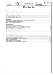
FP HOUSING<br />
Local control<br />
buttons<br />
(as an option with<br />
electronic positioner)<br />
<strong>INTEGRAL+</strong><br />
BOARD SETTING<br />
Configuration<br />
jumpers<br />
Lamp indicates<br />
actuat<strong>or</strong><br />
closing<br />
Lamp indicates<br />
actuat<strong>or</strong><br />
opening<br />
Electronic board<br />
configuration<br />
POSITIONER BOARD<br />
SETTING<br />
Potentiometer f<strong>or</strong><br />
setting of 100%<br />
Potentiometer f<strong>or</strong><br />
setting of dead-band<br />
Configuration switches<br />
1<br />
Terminal strip<br />
Configuration<br />
switches<br />
Lamp indicates<br />
thermal sens<strong>or</strong><br />
tripped<br />
Lamp indicates<br />
t<strong>or</strong>que switch<br />
tripped<br />
Secondary<br />
fuses<br />
Primary fuse<br />
Local control switch<br />
LED indicating<br />
actuat<strong>or</strong> running in<br />
open direction<br />
LED indicating<br />
actuat<strong>or</strong> running in<br />
close direction<br />
Potentiometer f<strong>or</strong><br />
local control
1. INTRODUCTION<br />
The configuration panel of the card <strong>INTEGRAL+</strong> allows to adapt the actuat<strong>or</strong> at each<br />
particular application. Inf<strong>or</strong>mation to be transmitted and actuat<strong>or</strong> behaviour configuration<br />
are set with switches and jumpers on the panel. The actuat<strong>or</strong> is deliverable with standard<br />
configuration, <strong>or</strong> optional configuration if requested at <strong>or</strong>der.<br />
The configuration can be change on site.<br />
2. CONFIGURATION<br />
Configuration is easily done by moving switches and jumpers.<br />
Figure 2 Figure 3<br />
Switches configuration Jumpers configuration<br />
B<br />
A<br />
SPECIFIC<br />
BASIC<br />
Configuration spécifique<br />
Configuration standard<br />
2<br />
A B<br />
BASIC SPECIFIC<br />
Configuration standard Configuration spécifique<br />
In " standard " configuration, the most common, all the switches and jumpers are in position<br />
A.<br />
3. POWER SUPPLY<br />
3.1. Actuat<strong>or</strong> power supply<br />
Actuat<strong>or</strong> power supply can be 3 phase, single phase <strong>or</strong> DC.<br />
☞ F Jumper 100 supp<strong>or</strong>t (located on lower board)<br />
The electronic board includes an automatic phase c<strong>or</strong>rection device and a detection of<br />
missing phase device. In 3 phase supply, whatever the power connection, the actuat<strong>or</strong><br />
always rotates in the right direction. If, in 3 phase supply, one phase is lost, the actuat<strong>or</strong><br />
stops automatically and the monit<strong>or</strong>ing relay drops.<br />
In single phase <strong>or</strong> DC supply, one must inhibit the automatic phase c<strong>or</strong>rection and the<br />
detection of missing phase by moving the jumper 100 to position M.<br />
➯ Single phase <strong>or</strong> DC power supply<br />
3.2 Output power supply<br />
One power supply unit 23V - 1,2VA DC is available (through the card CI2701) to power a<br />
remote position current transmitter and remote controls dry contacts. This power supply<br />
unit is isolated from the other electrical circuits
4. ACTUATOR OPERATION<br />
4.1 Direction of rotation<br />
In standard, the actuat<strong>or</strong> closes clockwise.<br />
☞ Switch 7<br />
Move the switch 7 to position B f<strong>or</strong> the valves closing counter-clockwise. This switch<br />
reverses :<br />
➩ The mot<strong>or</strong> direction of rotation<br />
➩ The limit switches<br />
➩ The t<strong>or</strong>que switches<br />
3<br />
➯ Closing counter-clockwise<br />
4.2 Closing type<br />
In standard, the actuat<strong>or</strong> closes on limit switch.<br />
☞ Switch 1<br />
Move switch 1 to position B f<strong>or</strong> closing on t<strong>or</strong>que switch (only f<strong>or</strong> actuat<strong>or</strong> equipped with<br />
t<strong>or</strong>que limit switches). The associated limit switch must also be operated when the valve is<br />
closed.<br />
➯ Closing on t<strong>or</strong>que switch<br />
The limit switch is used f<strong>or</strong> valve closed indication and also allows to detect stopping on<br />
t<strong>or</strong>que switch at mid-stroke as a fault and stopping on t<strong>or</strong>que switch in closed position as<br />
n<strong>or</strong>mal.<br />
4.3 By-pass of open t<strong>or</strong>que switch when starting to open from closed position<br />
In standard, the open t<strong>or</strong>que switch is active on the whole actuat<strong>or</strong> stroke.<br />
☞ Switch 6<br />
Move switch 6 to position B to by-pass the open t<strong>or</strong>que switch by the closed limit switch<br />
when starting to open from the closed<br />
position.<br />
➯ By-pass the open t<strong>or</strong>que switch by<br />
the closed limit switch in closed<br />
position<br />
This must be used when actuat<strong>or</strong> including mechanically maintained t<strong>or</strong>que switches [SR<br />
type] is set f<strong>or</strong> closing on t<strong>or</strong>que switch. This avoid the open t<strong>or</strong>que switch to trip when
4.4 Rotation reverse delay<br />
In standard the reverse delay is 50ms. Jumper on supp<strong>or</strong>t 25 in position 50ms.<br />
☞ Jumper supp<strong>or</strong>t 25<br />
Move the jumper on supp<strong>or</strong>t 25 to position 200ms to have a reverse delay of 200ms.<br />
➯ Reverse delay of 200 ms<br />
Note : the setting of the reverse delay is a fact<strong>or</strong>y setting. It allows the use of bigger single<br />
phase mot<strong>or</strong>s.<br />
5. REMOTE CONTROL<br />
Remote control of an actuat<strong>or</strong> equipped with the electronic board CI2701 can be done from<br />
an external voltage supply <strong>or</strong> an internal voltage supply..<br />
Inputs on the board are completely isolated by opto-isolat<strong>or</strong>s.<br />
Pulse commands (with self-holding) requires 4 wires connected to the customer terminal<br />
board: Common, stop, open and close. If the stop button is not used, do not connect the<br />
wire STOP, open contact (<strong>or</strong> close) must be maintained to operate the actuat<strong>or</strong>.<br />
5.1 Dry contacts control<br />
In case of dry contact control, a jumper must be put on customer terminals 31-32.<br />
5.2 Voltage control<br />
Remote control can be done either in AC <strong>or</strong> DC voltage.<br />
4
F<strong>or</strong> lower voltages from 10 to 55V, use common terminal 31.<br />
F<strong>or</strong> higher voltages from 55 to 250V, use common terminal 30<br />
Caution : do never connect voltage higher than 55V on common terminal 31.<br />
5.3 Single dry contact control<br />
It is possible to control the actuat<strong>or</strong> with a single external dry contact.<br />
➩ Contact closed : opening of the valve<br />
➩ Contact open : closing of the valve<br />
One must configure the actuat<strong>or</strong> f<strong>or</strong> pri<strong>or</strong>ity to open (see 5.4).<br />
The opposite control is possible :<br />
➩ Contact closed : closing of the valve<br />
➩ Contact open : opening of the valve<br />
One must configure the actuat<strong>or</strong> f<strong>or</strong> pri<strong>or</strong>ity to close (see 5.4)<br />
5.4 Pri<strong>or</strong>ity to Open <strong>or</strong> to Close<br />
In standard there is no pri<strong>or</strong>ity to open <strong>or</strong> to close. These pri<strong>or</strong>ities are used to :<br />
➩ Change the direction during operation without going through a stop command. In that<br />
case pri<strong>or</strong>ity to Open and to Close are needed.<br />
➩ Give pri<strong>or</strong>ity to one position : if the actuat<strong>or</strong> receives both open and close comand and<br />
a pri<strong>or</strong>ity to Open <strong>or</strong> to Close are needed.<br />
➩ <strong>Control</strong> by a single dry contact<br />
☞ Switch 9<br />
☞ Switch 10<br />
Move switch 9 to position B f<strong>or</strong> pri<strong>or</strong>ity to Close.<br />
Move switch 10 to position B f<strong>or</strong> pri<strong>or</strong>ity to Open<br />
5<br />
➯ Pri<strong>or</strong>ity to Close<br />
➯ Pri<strong>or</strong>ity to Open
6<br />
➯ Change of operation direction<br />
without going through a stop<br />
command<br />
Pri<strong>or</strong>ity command stops the pending operation and is immediately active.<br />
5.5 Emergency control (ESD)<br />
ESD (Emergency Shut Down) is a remote emergency control, with pri<strong>or</strong>ity on all other<br />
controls. Acc<strong>or</strong>ding to the valve operation, ESD can be open command <strong>or</strong> close command.<br />
To increase the availability of the actuat<strong>or</strong> in extreme conditions, ESD can also override the<br />
mot<strong>or</strong> thermal sens<strong>or</strong>.<br />
Note : ESD is not available when local / remote select<strong>or</strong> is in position "OFF".<br />
In standard, ESD control is perf<strong>or</strong>med by closing a contact. Jumper on supp<strong>or</strong>t 27 position<br />
.<br />
☞ Jumper supp<strong>or</strong>t 27<br />
Move jumper on supp<strong>or</strong>t 27 position to have ESD by opening a contact.<br />
Caution : In this configuration, if ESD input is not connected, the actuat<strong>or</strong> receives a<br />
operation command when powered on. It is theref<strong>or</strong>e recommended to add a jumper on the<br />
terminal board [in place of ESD] pri<strong>or</strong> to power on.<br />
In standard, ESD control is a close command. Jumper on supp<strong>or</strong>t 28 position CLOSE.<br />
☞ Jumper supp<strong>or</strong>t 28<br />
Move jumper on supp<strong>or</strong>t 28 to position OPEN f<strong>or</strong> open command.<br />
In standard, ESD control does not override the mot<strong>or</strong> thermal sens<strong>or</strong><br />
☞ Switch 8<br />
Move switch 8 to position B to by-pass the mot<strong>or</strong> thermal sens<strong>or</strong> when ESD control.<br />
➯ Configuration of ESD control: Jumper<br />
supp<strong>or</strong>t N°27 and N°28<br />
➯ By-pass of mot<strong>or</strong> thermal sens<strong>or</strong><br />
when ESD control.
5.6 Local control inhibition<br />
The inhibition of the local control is a remote command. This command freezes open and<br />
close commands sent in local and auth<strong>or</strong>ise remote commands even if the local / remote<br />
select<strong>or</strong> is in local position.<br />
In standard configuration, local stop and general stop remain possible locally on the<br />
actuat<strong>or</strong>.<br />
F<strong>or</strong> inhibition of local stop and general stop, see 6.3 (switch 4 on position B)<br />
Note : the command inhibition of local control is not available with the option positioner. It is<br />
replaced [automatically] by the function "AUTO / ON-OFF CONTROL".<br />
6. LOCAL CONTROL<br />
As f<strong>or</strong> remote control, local control can be used. A local select<strong>or</strong> allows to choose between<br />
remote and local control. The button f<strong>or</strong> local control open, close allows to operate the<br />
actuat<strong>or</strong> in the appropriate direction. Local stop is done by a momentary rotation of the local<br />
/ remote select<strong>or</strong>.<br />
6.1 Self-holding local control<br />
In standard, local controls are self-holding. (One pulse is enough to send a close <strong>or</strong> open<br />
command)<br />
☞ Switch 5<br />
Move switch 5 to position B to cancel the self-holding. (Open <strong>or</strong> close command must be<br />
maintained during the operation)<br />
7<br />
➯ Local control without self-holding.<br />
6.2 Local stop<br />
In standard, it is possible to stop the actuat<strong>or</strong> locally, even if the select<strong>or</strong> local / remote is<br />
on remote position.<br />
☞ Locking pin<br />
To inhibit a local stop when the select<strong>or</strong> is on remote position, fit the locking pin on the local<br />
/ remote select<strong>or</strong>.<br />
Note : This inhibition is effective only when the select<strong>or</strong> is padlocked in the remote position.
6.3 General stop<br />
In standard, it is possible to do a general stop of the actuat<strong>or</strong>. Move the select<strong>or</strong> local /<br />
remote to position OFF. No electrical controls in local <strong>or</strong> remote is theref<strong>or</strong>e possible.<br />
If the remote command " local control inhibition " is used, pri<strong>or</strong>ity remains to the function<br />
general stop.<br />
☞ Switch 4<br />
Move switch 4 to position B to prohibit local stop and OFF position when local control<br />
inhibition.<br />
8<br />
➯ Local stop impossible if local control<br />
inhibition.<br />
6.4 Local / remote select<strong>or</strong> padlock<br />
The local / remote select<strong>or</strong> can be padlocked in position OFF, local <strong>or</strong> remote.<br />
7. INDICATIONS<br />
Remote indication is done through 5 relays :<br />
➩ Four relays 'single contact' f<strong>or</strong> operation indications. Contacts can be n<strong>or</strong>mally open <strong>or</strong><br />
n<strong>or</strong>mally closed.<br />
Note : Voltage free, relays are always with n<strong>or</strong>mally open contact.<br />
➩ One reversing relay f<strong>or</strong> fault monit<strong>or</strong>ing.<br />
Note : The monit<strong>or</strong>ing relay is n<strong>or</strong>mally energised and drops in case of fault.<br />
Relays inf<strong>or</strong>mation :<br />
(Grey : standard configuration)<br />
N° Relay Inf<strong>or</strong>mation to be transmitted Location of Customer<br />
jumper terminal<br />
Relay 1 Limit switch open 14 - LSO 50 - 51<br />
T<strong>or</strong>que switch open 14 - TSO<br />
Relay 2 Limit switch close 15 - LSC 52 - 53<br />
T<strong>or</strong>que switch close 15 - TSC<br />
Limit switch open 16 - LSO 54 - 55<br />
T<strong>or</strong>que switch open 16 - TSO<br />
Relay 3 Local/remote select<strong>or</strong> on local 17 - LOCAL<br />
Local/remote select<strong>or</strong> on remote 17 - REMOTE<br />
Actuat<strong>or</strong> moving electrically 18 - RUNNING<br />
Actuat<strong>or</strong> opening electrically 18 - OPENING<br />
Limit switch close 19 - LSC 56 - 57<br />
T<strong>or</strong>que switch close 19 - TSC<br />
Relay 4 Actuat<strong>or</strong> receives an emergency command (ESD) 20 - ESD<br />
Actuat<strong>or</strong> closing electrically 20 - CLOSING<br />
Local/remote select<strong>or</strong> on local 21 - LOCAL<br />
Local/remote select<strong>or</strong> on remote 21 - REMOTE
7.1 Blinking indications<br />
In standard, inf<strong>or</strong>mation :<br />
➩ Actuat<strong>or</strong> running electrically<br />
➩ Actuat<strong>or</strong> opening electrically<br />
➩ Actuat<strong>or</strong> closing electrically<br />
are not blinking.<br />
☞ Switch 11<br />
Move switch 11 to position B to have the 3 inf<strong>or</strong>mation blinking<br />
9<br />
Indications<br />
➩ Actuat<strong>or</strong> running<br />
➩ Actuat<strong>or</strong> opening<br />
➩ Actuat<strong>or</strong> closing<br />
are blinking<br />
7.2 Indication relay N°1<br />
In standard, relay N°1 indicates limit switch open. Jumper on supp<strong>or</strong>t 14 in position LSO<br />
(Limit Switch Open).<br />
☞ Jumper supp<strong>or</strong>t 14<br />
Move jumper on supp<strong>or</strong>t 14 to position TSO (T<strong>or</strong>que Switch Open) f<strong>or</strong> relay N°1 to indicate<br />
t<strong>or</strong>que switch open.<br />
In standard, relay N°1 is with contact n<strong>or</strong>mally open. Jumper on supp<strong>or</strong>t 22 in position<br />
☞ Jumper supp<strong>or</strong>t 22<br />
Move jumper on supp<strong>or</strong>t 22 position f<strong>or</strong> relay N°1 to be with contact n<strong>or</strong>mally close.<br />
➯ Configuration relay 1 : jumper supp<strong>or</strong>t N°14 and N°22<br />
7.3 Indication relay N°2<br />
In standard, relay N°2 indicates limit switch close. Jumper on supp<strong>or</strong>t 15 in position LSC<br />
(Limit Switch Close).<br />
☞ Jumper supp<strong>or</strong>t 15<br />
Move jumper on supp<strong>or</strong>t 15 to position TSC (T<strong>or</strong>que Switch Close) f<strong>or</strong> relay N°2 to indicate<br />
t<strong>or</strong>que switch close.<br />
In standard, relay N°2 is with contact n<strong>or</strong>mally open. Jumper on supp<strong>or</strong>t 23 in position<br />
☞ Jumper supp<strong>or</strong>t 23<br />
Move jumper on supp<strong>or</strong>t 23 to position f<strong>or</strong> relay N°2 to be with contact n<strong>or</strong>mally closed.
➯ Configuration relay 2 : Jumper supp<strong>or</strong>t N°15 and N°23<br />
7.4 Indication relay N°3<br />
In standard, relay N°3 indicates limit switch open. Jumper on supp<strong>or</strong>t 16 in position LSO<br />
(Limit Switch Open).<br />
☞ Jumper supp<strong>or</strong>t 16<br />
☞ Jumper supp<strong>or</strong>t 17<br />
☞ Jumper supp<strong>or</strong>t 18<br />
➩ Move jumper on supp<strong>or</strong>t 16 to position TSO (T<strong>or</strong>que Switch Open) f<strong>or</strong> relay N°3 to<br />
indicate t<strong>or</strong>que switch open.<br />
➩ Move jumper on supp<strong>or</strong>t 17 to position REMOTE f<strong>or</strong> relay N°3 to indicate local/remote<br />
select<strong>or</strong> in position remote.<br />
➩ Move jumper on supp<strong>or</strong>t 17 to position LOCAL f<strong>or</strong> relay N°3 to indicate local/remote<br />
select<strong>or</strong> in position local.<br />
➩ Move jumper on supp<strong>or</strong>t 18 to position OPENING f<strong>or</strong> relay N°3 to indicate that actuat<strong>or</strong><br />
is running in opening direction.<br />
➩ Move jumper on supp<strong>or</strong>t 18 to position RUNNING f<strong>or</strong> relay N°3 to indicate that actuat<strong>or</strong><br />
is running.<br />
In standard, relay N°3 is with contact n<strong>or</strong>mally open. Jumper on supp<strong>or</strong>t 24 in position<br />
☞ Jumper supp<strong>or</strong>t 24<br />
Move jumper on supp<strong>or</strong>t 24 to position f<strong>or</strong> relay N°3 to be with contact n<strong>or</strong>mally closed.<br />
➯ Configuration relay 3 : jumper supp<strong>or</strong>t N°16, 17, 18 and<br />
N°24.<br />
➯ 1 unique jumper f<strong>or</strong> supp<strong>or</strong>ts 16,17 and 18.<br />
7.5 Indication relay N°4<br />
In standard, relay N°4 indicates limit switch closed. Jumper on supp<strong>or</strong>t 19 in position LSC<br />
(Limit Switch Close).<br />
☞ Jumper supp<strong>or</strong>t 19<br />
☞ Jumper supp<strong>or</strong>t 20<br />
☞ Jumper supp<strong>or</strong>t 21<br />
➩ Move jumper on supp<strong>or</strong>t 19 to position TSC (T<strong>or</strong>que Switch Close) f<strong>or</strong> relay N°4 to<br />
indicate t<strong>or</strong>que switch close.<br />
10
➩ Move jumper on supp<strong>or</strong>t 20 to position CLOSING f<strong>or</strong> relay N°4 to indicate that actuat<strong>or</strong><br />
is running in closed direction.<br />
➩ Move jumper on supp<strong>or</strong>t 20 to position ESD (Emergency Shut Down) f<strong>or</strong> relay N°4 to<br />
indicate that actuat<strong>or</strong> is receiving an ESD command.<br />
➩ Move jumper on supp<strong>or</strong>t 21 to position REMOTE f<strong>or</strong> relay N°4 to indicate local/remote<br />
select<strong>or</strong> in position remote.<br />
➩ Move jumper on supp<strong>or</strong>t 21 to position LOCAL f<strong>or</strong> relay N°4 to indicate local/remote<br />
select<strong>or</strong> in position local.<br />
In standard, relay N°4 is with contact n<strong>or</strong>mally open. Jumper on supp<strong>or</strong>t 26 in position<br />
☞ Jumper supp<strong>or</strong>t 26<br />
Move jumper on supp<strong>or</strong>t 26 to position f<strong>or</strong> relay N°4 to be with contact n<strong>or</strong>mally closed.<br />
➯ Configuration relay 4 : jumper supp<strong>or</strong>t N°19, 20, 21 and<br />
N°26<br />
➯ 1 unique jumper f<strong>or</strong> supp<strong>or</strong>ts 19, 20 and 21<br />
7.6 Fault monit<strong>or</strong>ing relay<br />
The fault monit<strong>or</strong>ing relay indicates a non-availability of the actuat<strong>or</strong> <strong>or</strong> an abn<strong>or</strong>mal<br />
operation. The fault monit<strong>or</strong>ing relay is n<strong>or</strong>mally energised, and is disenergised in case of<br />
fault.<br />
The relay is disenergised upon the following events:<br />
➩ Loss of main power supply, control voltage, fuse.<br />
➩ Loss of 1 phase (in case of 3 phase supply)<br />
➩ Tripping of mot<strong>or</strong> thermal protection<br />
➩ Loss of input signal 4-20mA (with option positioner)*<br />
➩ Local/remote select<strong>or</strong> in position local <strong>or</strong> off**<br />
* On version without positioner, switch N°2 has no effect.<br />
** In case of local controls inhibition, select<strong>or</strong> in position local is not indicated as a fault, because actuat<strong>or</strong> is<br />
still available f<strong>or</strong> the remote commands.<br />
The user can modify the conditions upon which the relay is disenergised.<br />
☞ Switch 2<br />
Move switch 2 to position B f<strong>or</strong> loss of input signal 4-20mA not indicated as a fault. (Option<br />
positioner only).<br />
☞ Switch 3<br />
Move switch 3 to position B f<strong>or</strong> local/remote select<strong>or</strong> in local <strong>or</strong> off not indicated as a fault.<br />
☞ Switch 12<br />
Move switch 12 to position B f<strong>or</strong> tripping of t<strong>or</strong>que switch open to be a fault.<br />
☞ Switch 13<br />
Move switch 13 to position B f<strong>or</strong> tripping of t<strong>or</strong>que switch close to be a fault.<br />
11
12<br />
➯ Loss of input signal 4-20mA is not a<br />
fault. (Option positioner only).<br />
➯ Local/remote select<strong>or</strong> in local <strong>or</strong> off is<br />
not a fault.<br />
➯ Tripping of t<strong>or</strong>que switch close is a<br />
fault.<br />
➯ Tripping of t<strong>or</strong>que switch open is a<br />
fault.<br />
Note : Supervis<strong>or</strong> system is able to detect if the valve close on t<strong>or</strong>que, and in this case there<br />
is no fault indication<br />
8. FUSES PROTECTION<br />
Accessibility :<br />
➩ Switch off power supply on actuat<strong>or</strong>.<br />
➩ Remove cover on terminal box.<br />
➩ Unfasten the 4 screws located near the covers screws.<br />
➩ Move a few centimetres backward the electric block, until seeing on the side the fuses<br />
supp<strong>or</strong>ts.<br />
➩ Unfasten the covers and change the fuses if necessary.<br />
Fuses data :<br />
FU1 : transf<strong>or</strong>mer primary fuse 6,3 x 32mm - 0,5A - 500V<br />
FU2 : transf<strong>or</strong>mer secondary fuse 5 x 20mm - 0,5A<br />
FU3 : transf<strong>or</strong>mer secondary fuse 5 x 20mm - 0,05A
9. POSITIONER OPTION<br />
The option positioner is connected to the basic board CI2701. The positioner allows the<br />
actuat<strong>or</strong> to reach a position prop<strong>or</strong>tionally to a command input signal. The configuration<br />
panel of L. BERNARD positioner allows:<br />
➩ To give local positioning commands<br />
➩ To adapt the actuat<strong>or</strong> to the type of input signal<br />
➩ To configure the reaction of the actuat<strong>or</strong> in case of loss of input signal<br />
9.1 Input signal configuration<br />
The standard input signal is 4-20 mA<br />
9.1.1 Operation with signal 0-20 mA<br />
☞ Switch 4<br />
☞ Switch 8<br />
Move switches 4 and 8 to position B f<strong>or</strong> operation with signal 0-20mA. The output signal<br />
[position indication] is also 0-20 mA.<br />
9.1.2 Operation with signal 0-10 V<br />
☞ Switch 4<br />
☞ Switch 8<br />
☞ Switch 9<br />
☞ Switch 10<br />
Move switches 4, 8, 9 and 10 to position B f<strong>or</strong> operation with signal 0-10 V. The output signal<br />
is 0-20 mA.<br />
9.2 Operation direction configuration<br />
The standard is 4 mA valve closed and 20 mA valve open.<br />
☞ Switch 3<br />
☞ Potentiometer connection<br />
Move switch 3 to position B, and move actuat<strong>or</strong> potentiometer connection from position<br />
"POT STD" to position "POT REV" to obtain 4 mA valve open, and 20 mA valve closed.<br />
Type of input<br />
signal<br />
Valve action<br />
Closing<br />
clockwise<br />
Configuration Standard<br />
Operation direction configuration<br />
Open<br />
4mA 20mA<br />
0mA 20mA<br />
0v 10V<br />
Closing counterclockwise<br />
Card CI2701 :<br />
switch 7 on B<br />
Reverse<br />
potentiometer<br />
13<br />
Closing<br />
clockwise<br />
Close<br />
4mA 20mA<br />
0mA 20mA<br />
Card GAMK :<br />
switch 3 on B<br />
Reverse<br />
potentiometer<br />
0v 10V<br />
Closing counterclockwise<br />
Card CI2701 :<br />
switch 7 on B<br />
Card GAMK :<br />
switch 3 on B
9.3 'Stay put' function configuration<br />
With input signal 4-20 mA, it is possible to configure a failsafe position in case of loss of<br />
input signal.<br />
In standard, the function is active, and the actuat<strong>or</strong> stays in position in case of loss of input<br />
signal.<br />
☞ Switch 5<br />
☞ Switch 6<br />
☞ Switch 8<br />
Move switch 5 to position B f<strong>or</strong> actuat<strong>or</strong> to open in case of loss of input signal<br />
Move switch 6 to position B f<strong>or</strong> actuat<strong>or</strong> to close in case of loss of input signal<br />
Move switch 8 to position B to disactivate the 'stay put' function.<br />
Caution : in case of input signal 0-20 mA <strong>or</strong> 0-10 V, the 'stay put' function cannot be used<br />
and must be disactivated. Move switch 8 to position B.<br />
9.4 Dead band adjustment<br />
This adjustment is fact<strong>or</strong>y done, but one can adjust it with the potentiometer "DEAD BAND".<br />
To reduce the dead band turn it counter-clockwise.<br />
Caution : Reducing the dead band too much will provoke "hunting" on the actuat<strong>or</strong>.<br />
9.5 Local operation<br />
One can simulate an input signal 4-20 mA locally to check the operation of the actuat<strong>or</strong>. The<br />
local/off/remote select<strong>or</strong> must be on the remote position<br />
➩ AUT : Operation by external signal<br />
➩ 0% : Internal signal 0% (4mA in standard)<br />
➩ MAN : Internal signal adjustable from 0 to 100%<br />
➩ 100 % : Internal signal 100% (20mA in standard)<br />
Move local control switch to position 0%, MAN <strong>or</strong> 100%. Turn potentiometer "MAN" to<br />
simulate an input signal 4-20 mA.<br />
9.6 Adjustment of 0%<br />
The local/off/remote select<strong>or</strong> must be on remote position. Move local control switch to<br />
position 0% f<strong>or</strong> the actuat<strong>or</strong> to receive a closing command (4mA).<br />
Case N°1 : actuat<strong>or</strong> starts closing and stops bef<strong>or</strong>e the close limit switch.<br />
Turn actuat<strong>or</strong> potentiometer progressively to bring the actuat<strong>or</strong> on the close limit<br />
switch, LED on. Turn potentiometer slowly in opposite direction until the red LED<br />
goes off.<br />
14
Case N°2:actuat<strong>or</strong> starts closing, stops on the close limit switch, and the LED<br />
indicating closing is still on.<br />
Turn actuat<strong>or</strong> potentiometer progressively to off the LED.<br />
9.7 Adjustment of 100%<br />
The local/off/remote select<strong>or</strong> must be on remote position. Move local control switch to<br />
position 100% f<strong>or</strong> the actuat<strong>or</strong> to receive an opening command (20mA).<br />
Case N°1:actuat<strong>or</strong> starts opening and stops bef<strong>or</strong>e the open limit switch.<br />
Turn potentiometer "ADJ 100%" (adjustment of 100%) progressively clockwise<br />
to bring the actuat<strong>or</strong> on the open limit switch. Turn slowly this potentiometer in<br />
opposite direction until the green LED goes off.<br />
Case N°2:actuat<strong>or</strong> starts opening, stops on the open limit switch, and the green LED<br />
is still on.<br />
Turn potentiometer "ADJ 100%" (adjustment of 100%) progressively counterclockwise<br />
to off the green LED.<br />
9.8 Split Range<br />
The positioner card can be configured f<strong>or</strong> split range.<br />
Split range means input signals 4-12mA and 12-20mA. The end user signal is n<strong>or</strong>mal :4-<br />
20mA. A first actuat<strong>or</strong> is set to receive a signal from 4 to 12mA and a second actuat<strong>or</strong> is<br />
set to receive a signal from 12 to 20mA. Each actuat<strong>or</strong> receives the signal 4-20mA. The<br />
first one opens completely from 0 to 50% of the signal and the second from 50 to 100%<br />
of the signal.<br />
☞ Switch 1<br />
☞ Switch 2<br />
Move switch 1 to position B f<strong>or</strong> the actuat<strong>or</strong> to receive an input signal 12-20mA.<br />
Move switch 2 to position B f<strong>or</strong> the actuat<strong>or</strong> to receive an input signal 4-12mA.<br />
9.9 Operation with a transmitter 4-20mA<br />
In standard the actuat<strong>or</strong> potentiometer is used to know the valve position.<br />
☞ Switch 7<br />
Move switch 7 to position B f<strong>or</strong> operation with a transmitter 4-20mA instead of the actuat<strong>or</strong><br />
potentiometer. The CI2701 board can provide the power supply to the transmitter TAM <strong>or</strong><br />
FSG.<br />
15
9.10 Remote control AUTO / ON-OFF CONTROL<br />
With a positioner, one can do remote control by a signal 4-20mA <strong>or</strong> by open/close/stop<br />
commands. The input AUTO / ON-OFF CONTROL on the customer terminal board allows<br />
to switch from one type of control to the other one.<br />
See chapter 5 "remote control" f<strong>or</strong> the configuration of the open and close commands.<br />
Note : The remote controls " AUTO / ON-OFF CONTROL " and "LOCAL CONTROL<br />
INHIBITION" use the same input on the customer terminal board. The implementation of<br />
the positioner automatically allocates this input to the function AUTO / ON-OFF CONTROL.<br />
The function "LOCAL CONTROL INHIBITION" cannot be used with a positioner.<br />
10. OPTION TIMING CONTROL BOARD<br />
The timing control board allows to reduce the operating speed of the actuat<strong>or</strong>, to protect f<strong>or</strong><br />
example a pipeline from the effects of hammering.<br />
This additional board is connected with the main board.<br />
Two potentiometers allow to set the running time and the stop time f<strong>or</strong> an intermittent<br />
operation.. (The settings in open and close direction are independents).<br />
One can use an additional limit switch to start the intermittent operation from a preset<br />
position.<br />
11. OPTION LOCAL INDICATION<br />
In option a local indication through a window at the local controls level shows the actuat<strong>or</strong><br />
status.<br />
➩ Lamp valve open<br />
➩ Lamp valve closed<br />
➩ Lamp actuat<strong>or</strong> power-on<br />
16
12. FUNCTIONAL FAULTS OF <strong>INTEGRAL+</strong> VERSION<br />
In case of doubt as to the unit's functionality, firstly set the local/remote select<strong>or</strong> switch to<br />
"local" and actuate the local open/close controls.<br />
PROBLEM<br />
No operation<br />
CAUSE<br />
Actuat<strong>or</strong> power supply<br />
A local control inhibit<br />
command is present.<br />
An emergency control<br />
command is present and<br />
inhibits all other<br />
commands.<br />
Fuse blown<br />
Power supply type<br />
configuration<br />
Tripping of mot<strong>or</strong> thermal<br />
protective device<br />
The declutchable manual<br />
control handwheel<br />
remained engaged (only on<br />
versions with electrical<br />
safety contact)<br />
Configuration jumpers are<br />
inc<strong>or</strong>rectly set <strong>or</strong> missing<br />
17<br />
CORRECTIVE ACTION<br />
Check the power supply voltage<br />
(terminals L1, L2, L3 in 3 PH voltage).<br />
The voltage is specified on the<br />
identification plate.<br />
Check that the Actuat<strong>or</strong> receives no local<br />
control inhibit command.<br />
With the unit "off", the local control inhibit<br />
wire, connected to terminal 37 may be<br />
removed to carry out a functional check of<br />
the Actuat<strong>or</strong>.<br />
Check that the Actuat<strong>or</strong> receives no<br />
emergency command.<br />
With the unit "off", jumper #27 may be<br />
removed from the "integral+" board,<br />
taking care to rec<strong>or</strong>d its position to make<br />
sure it is replaced at the c<strong>or</strong>rect location.<br />
With the jumper removed, the ESD<br />
function is inhibited, and a functional<br />
check of the Actuat<strong>or</strong> can be carried out.<br />
Return the jumper to <strong>or</strong>iginal location.<br />
Check fuses and replace as required.<br />
Check position of jumper 100 on the<br />
"Integral+" board.<br />
Three-phase : position T<br />
Single-phase <strong>or</strong> DC: position M<br />
The TH light on the "Integral+" board<br />
configuration panel indicates thermal<br />
tripping of thermal protective device. The<br />
Actuat<strong>or</strong> will again be available after the<br />
mot<strong>or</strong> has cooled off.<br />
Check that the handwheel is in<br />
disengaged position.<br />
There must be 11 jumpers on the<br />
"Integral+" board.<br />
There shall be only one jumper on jumper<br />
16-17-18 supp<strong>or</strong>t and only one jumper on<br />
jumper 19-20-21 supp<strong>or</strong>t.
PROBLEM<br />
The actuat<strong>or</strong><br />
operates in<br />
local mode, not<br />
in remote<br />
mode<br />
The actuat<strong>or</strong><br />
operates in<br />
remote mode,<br />
not in local<br />
mode<br />
The actuat<strong>or</strong><br />
does not rotate<br />
in the c<strong>or</strong>rect<br />
rotational<br />
direction<br />
The Actuat<strong>or</strong><br />
does not stop<br />
on the closing<br />
limit switch<br />
The Actuat<strong>or</strong><br />
does not stop<br />
on the opening<br />
limit switch<br />
CAUSE<br />
Local/remote select<strong>or</strong><br />
switch set to local <strong>or</strong> to off<br />
Contact control: no voltage<br />
across terminals 32 and<br />
33.<br />
Voltage control:<br />
inappropriate input voltage.<br />
Local/remote select<strong>or</strong><br />
switch set to remote <strong>or</strong> to<br />
off<br />
A local control inhibit<br />
command is present.<br />
Configuration inc<strong>or</strong>rect<br />
The mot<strong>or</strong> has been<br />
unwired and rotates in the<br />
reverse direction (mot<strong>or</strong><br />
replacement)<br />
The Actuat<strong>or</strong> is configured<br />
f<strong>or</strong> t<strong>or</strong>que closing.<br />
The closing limit switch is<br />
misadjusted.<br />
The mot<strong>or</strong> has been<br />
unwired and rotates in the<br />
reverse direction (mot<strong>or</strong><br />
replacement)<br />
The opening limit switch is<br />
misadjusted.<br />
The mot<strong>or</strong> has been<br />
unwired and rotates in the<br />
reverse direction (mot<strong>or</strong><br />
replacement)<br />
18<br />
CORRECTIVE ACTION<br />
Set the local/remote select<strong>or</strong> switch to<br />
remote.<br />
Check that a shunt is present at the client<br />
terminal strip between terminals 31 and<br />
32.<br />
Check fuse FU3 on the "Integral+" board.<br />
Check connection in voltage control<br />
mode:<br />
Voltage 10 to 55 V: Terminal strip 31<br />
Voltage 55 to 250 V: Terminal strip 30<br />
Set the local/remote select<strong>or</strong> switch to<br />
local.<br />
Check that the Actuat<strong>or</strong> receives no local<br />
control inhibit command.<br />
With the unit "off", the local control inhibit<br />
wire, connected to terminal 37 may be<br />
removed to carry out a functional check of<br />
the Actuat<strong>or</strong>.<br />
Check the rotational direction<br />
configuration. Switch #7 of the "Integral+"<br />
board:<br />
Position A: clockwise closing<br />
Position B: counterclockwise closing<br />
When replacing a mot<strong>or</strong>, wire markings<br />
must be observed. In case of doubt,<br />
check rotational direction. To reverse the<br />
mot<strong>or</strong> rotational direction, change over<br />
wires 2 and 3 of the mot<strong>or</strong> terminal strip.<br />
Check closing configuration (switch 1 of<br />
the "Integral+" board.<br />
Adjust the closing limit switch. The closing<br />
limit switch must be actuated with the<br />
valve closed (even if the Actuat<strong>or</strong> is set<br />
f<strong>or</strong> t<strong>or</strong>que closing).<br />
When replacing a mot<strong>or</strong>, wire markings<br />
must be observed. In case of doubt,<br />
check rotational direction. To reverse the<br />
mot<strong>or</strong> rotational direction, change over<br />
wires 2 and 3 of the mot<strong>or</strong> terminal strip.<br />
Adjust the opening limit switch. The<br />
opening limit switch must be actuated<br />
with the valve open.<br />
When replacing a mot<strong>or</strong>, wire markings<br />
must be observed. In case of doubt,<br />
check rotational direction. To reverse the<br />
mot<strong>or</strong> rotational direction, change over<br />
wires 2 and 3 of the mot<strong>or</strong> terminal strip.
PROBLEM<br />
Indications are<br />
inoperative<br />
The t<strong>or</strong>que<br />
limiter<br />
indications are<br />
inoperative<br />
The t<strong>or</strong>que<br />
limiter<br />
indication does<br />
not return to<br />
initial condition<br />
once the<br />
t<strong>or</strong>que limiter is<br />
no longer<br />
actuated.<br />
CAUSE<br />
The Actuat<strong>or</strong> is "off"<br />
Configuration inc<strong>or</strong>rect<br />
The t<strong>or</strong>que limiter has been<br />
actuated manually.<br />
T<strong>or</strong>que limiter data st<strong>or</strong>age<br />
19<br />
CORRECTIVE ACTION<br />
Indications are only available with the<br />
Actuat<strong>or</strong> "on".<br />
Check that the concerned indication relay<br />
has been configured f<strong>or</strong> t<strong>or</strong>que limiter<br />
indication. The jumper of the "Integral+"<br />
board is set to:<br />
TS0 f<strong>or</strong> opening t<strong>or</strong>que limiter<br />
TSC f<strong>or</strong> closing t<strong>or</strong>que limiter<br />
The electronics only st<strong>or</strong>e the limiter data<br />
if a manoeuvre is in progress. The<br />
electronics further only st<strong>or</strong>es the data f<strong>or</strong><br />
the t<strong>or</strong>que limiter c<strong>or</strong>responding to the<br />
rotational direction.<br />
The t<strong>or</strong>que limiter data are st<strong>or</strong>ed<br />
electronically. To clear a t<strong>or</strong>que limiter<br />
mem<strong>or</strong>y, a reverse <strong>or</strong>der must be sent.
13 FUNCTIONAL FAULTS OF POSITIONER VERSIONS<br />
In case of doubt as to the unit's functionality, firstly set the local/remote select<strong>or</strong> switch to<br />
"local" and actuate the local open/close controls.<br />
PROBLEM<br />
No operation<br />
CAUSE<br />
Actuat<strong>or</strong> power supply<br />
An emergency control<br />
command is present and<br />
inhibits all other<br />
commands.<br />
Fuse blown<br />
Power supply type<br />
configuration<br />
Tripping of mot<strong>or</strong> thermal<br />
protective device<br />
The declutchable manual<br />
control handwheel<br />
remained engaged (only on<br />
versions with electrical<br />
safety contact)<br />
Configuration jumpers are<br />
inc<strong>or</strong>rectly set <strong>or</strong> missing<br />
20<br />
CORRECTIVE ACTION<br />
Check the power supply voltage<br />
(terminals L1, L2, L3 in three-phase<br />
voltage). The voltage is specified on the<br />
identification plate.<br />
Check that the Actuat<strong>or</strong> receives no<br />
emergency control command.<br />
With the unit "off", jumper #27 may be<br />
removed from the "integral+" board,<br />
taking care to rec<strong>or</strong>d its position to make<br />
sure it is replaced at the c<strong>or</strong>rect location.<br />
With the jumper removed, the ESD<br />
function is inhibited, and a functional<br />
check of the Actuat<strong>or</strong> can be carried out.<br />
Return the jumper to <strong>or</strong>iginal location.<br />
Check fuses of "Integral+" board and<br />
replace as required.<br />
Check position of jumper 100 on the<br />
"Integral+" board.<br />
Three-phase : position T<br />
Single-phase <strong>or</strong> DC: position M<br />
The TH light on the "Integral+" board<br />
configuration panel indicates thermal<br />
tripping of thermal protective device. The<br />
Actuat<strong>or</strong> will again be available after the<br />
mot<strong>or</strong> has cooled off.<br />
Check that the handwheel is in<br />
disengaged position.<br />
There must be 11 jumpers on the<br />
"Integral+" board.<br />
There shall be only one jumper on jumper<br />
16-17-18 supp<strong>or</strong>t and only one jumper on<br />
jumper 19-20-21 supp<strong>or</strong>t.
PROBLEM<br />
The actuat<strong>or</strong><br />
operates in<br />
local<br />
open/close<br />
control mode,<br />
not in<br />
positioner<br />
mode<br />
The Actuat<strong>or</strong><br />
operates in<br />
positioner<br />
mode in local<br />
mode, not in<br />
remote mode<br />
CAUSE<br />
Local/remote select<strong>or</strong><br />
switch set to local <strong>or</strong> to off<br />
An auto/on-off control <strong>or</strong>der<br />
is present and inhibits the<br />
positioner.<br />
The connect<strong>or</strong> connecting<br />
the positioner board to the<br />
"Integral+" board is<br />
disconnected.<br />
The actuat<strong>or</strong> repeater<br />
potentiometer is inc<strong>or</strong>rectly<br />
set<br />
Input signal inc<strong>or</strong>rect<br />
The Auto - 0% - 100%<br />
switch is not set to Auto<br />
Signal defective<br />
Signal polarity<br />
21<br />
CORRECTIVE ACTION<br />
Set the local/remote select<strong>or</strong> switch to<br />
remote to use the positioner (even when<br />
the positioner is set to manual).<br />
Check that the Actuat<strong>or</strong> receives no<br />
Auto/on-off control command.<br />
Disconnect this remote control (terminal<br />
37) as required f<strong>or</strong> confirmation.<br />
Check the positioner board-Integral board<br />
connection.<br />
Turn the Actuat<strong>or</strong> potentiometer by a<br />
quarter-turn and repeat adjustments in<br />
acc<strong>or</strong>dance with commissioning<br />
instructions.<br />
Check input signal configuration on the<br />
positioner board:<br />
4-20 mA signal:<br />
Switch 4 set to A<br />
Switch 9 set to A<br />
Switch 10 set to A<br />
0-20 mA signal:<br />
Switch 4 set to B<br />
Switch 8 set to B<br />
Switch 9 set to A<br />
Switch 10 set to A<br />
0-10 V signal:<br />
Switch 4 set to B<br />
Switch 8 set to B<br />
Switch 9 set to B<br />
Switch 10 set to B<br />
Check setting of Auto - 0% - 100% switch<br />
on the positioner board.<br />
Check the reference signal using a<br />
milliammeter connected in series<br />
(terminal 70).<br />
Check that the plus (+) of the signal is<br />
present at terminal 70
PROBLEM<br />
The Actuat<strong>or</strong><br />
does not follow<br />
the input signal<br />
The Actuat<strong>or</strong><br />
does not stop<br />
on the closing<br />
limit switch<br />
CAUSE<br />
Potentiometer reversemounted<br />
Signal reversed <strong>or</strong><br />
configuration inc<strong>or</strong>rect<br />
Rotational direction<br />
reversed<br />
The Actuat<strong>or</strong> repeater<br />
potentiometer is inc<strong>or</strong>rectly<br />
set<br />
The mot<strong>or</strong> has been<br />
unwired and rotates in the<br />
reverse direction (mot<strong>or</strong><br />
replacement)<br />
The Actuat<strong>or</strong> is configured<br />
f<strong>or</strong> t<strong>or</strong>que closing.<br />
The closing limit switch is<br />
misadjusted.<br />
Position 0% is misadjusted<br />
The mot<strong>or</strong> has been<br />
unwired and rotates in the<br />
reverse direction (mot<strong>or</strong><br />
replacement)<br />
22<br />
CORRECTIVE ACTION<br />
Check the potentiometer connection.<br />
The potentiometer should be connected<br />
to "POT STD" f<strong>or</strong>:<br />
• 4 mA (<strong>or</strong> (0 mA <strong>or</strong> 0 V acc<strong>or</strong>ding to<br />
signal) = closed position and clockwise<br />
direction closing.<br />
• 4 mA (<strong>or</strong> (0 mA <strong>or</strong> 0 V acc<strong>or</strong>ding to<br />
signal) = open position and<br />
counterclockwise direction closing<br />
The potentiometer should be connected<br />
to "POT REV" f<strong>or</strong>:<br />
• 4 mA (<strong>or</strong> (0 mA <strong>or</strong> 0 V acc<strong>or</strong>ding to<br />
signal) = closed position and<br />
counterclockwise direction closing.<br />
• 4 mA (<strong>or</strong> (0 mA <strong>or</strong> 0 V acc<strong>or</strong>ding to<br />
signal) = open position and clockwise<br />
direction closing<br />
Check signal configuration.<br />
Switch #3 on positioner board:<br />
Position A: 4 mA = valve closed<br />
Position B: 4 mA = valve open<br />
Check signal configuration.<br />
Switch #3 on "Integral+" board:<br />
Position A: clockwise direction closing<br />
Position B: counterclockwise direction<br />
opening<br />
Turn the Actuat<strong>or</strong> potentiometer by a<br />
quarter-turn and repeat adjustments in<br />
acc<strong>or</strong>dance with commissioning<br />
instructions.<br />
When replacing a mot<strong>or</strong>, wire markings<br />
must be observed. In case of doubt,<br />
check rotational direction. To reverse the<br />
mot<strong>or</strong> rotational direction, change over<br />
wires 2 and 3 of the mot<strong>or</strong> terminal strip.<br />
Check closing configuration (switch 1 of<br />
the "Integral+" board.<br />
Adjust the closing limit switch. The closing<br />
limit switch must be actuated with the<br />
valve closed (even if the Actuat<strong>or</strong> is set<br />
f<strong>or</strong> t<strong>or</strong>que closing).<br />
Adjust Actuat<strong>or</strong> potentiometer<br />
When replacing a mot<strong>or</strong>, wire markings<br />
must be observed. In case of doubt,<br />
check rotational direction. To reverse the<br />
mot<strong>or</strong> rotational direction, change over<br />
wires 2 and 3 of the mot<strong>or</strong> terminal strip.
PROBLEM<br />
The Actuat<strong>or</strong><br />
does not stop<br />
on the opening<br />
limit switch<br />
Indications are<br />
inoperative<br />
The t<strong>or</strong>que<br />
limiter<br />
indications are<br />
inoperative<br />
The t<strong>or</strong>que<br />
limiter indication<br />
does not return<br />
to initial reading<br />
once the t<strong>or</strong>que<br />
limiter is no<br />
longer actuated.<br />
A fault is<br />
indicated but<br />
the Actuat<strong>or</strong> is<br />
fully functional.<br />
CAUSE<br />
The opening limit switch is<br />
misadjusted.<br />
Position 100% is<br />
misadjusted<br />
The mot<strong>or</strong> has been<br />
unwired and rotates in the<br />
reverse direction (mot<strong>or</strong><br />
replacement)<br />
The Actuat<strong>or</strong> is "off"<br />
Configuration inc<strong>or</strong>rect<br />
The load limiter has been<br />
actuated manually.<br />
T<strong>or</strong>que limiter data st<strong>or</strong>age<br />
The datum signal is not<br />
present. In standard<br />
configuration, the Actuat<strong>or</strong><br />
indicates a fault and<br />
remains in position<br />
The select<strong>or</strong> switch is set<br />
to "local" <strong>or</strong> "off" position. In<br />
standard configuration the<br />
Actuat<strong>or</strong> indicates a fault.<br />
23<br />
CORRECTIVE ACTION<br />
Adjust the opening limit switch. The<br />
opening limit switch must be actuated<br />
with the valve open.<br />
Adjust 100% potentiometer on positioner<br />
board.<br />
When replacing a mot<strong>or</strong>, wire markings<br />
must be observed. In case of doubt,<br />
check rotational direction. To reverse the<br />
mot<strong>or</strong> rotational direction, change over<br />
wires 2 and 3 of the mot<strong>or</strong> terminal strip.<br />
Indications are only available with the<br />
Actuat<strong>or</strong> "on".<br />
Check that the concerned indication relay<br />
has been configured f<strong>or</strong> t<strong>or</strong>que limiter<br />
indication. The jumper of the "Integral+"<br />
board is set to:<br />
TS0 f<strong>or</strong> opening t<strong>or</strong>que limiter<br />
TSC f<strong>or</strong> closing t<strong>or</strong>que limiter<br />
The electronics only st<strong>or</strong>e the limiter data<br />
if a manoeuvre is in progress. The<br />
electronics further only st<strong>or</strong>es the data f<strong>or</strong><br />
the load limiter c<strong>or</strong>responding to the<br />
rotational direction.<br />
The t<strong>or</strong>que limiter data are st<strong>or</strong>ed<br />
electronically. To clear a t<strong>or</strong>que limiter<br />
mem<strong>or</strong>y, a reverse <strong>or</strong>der must be sent.<br />
Send a control signal on the input<br />
Set the select<strong>or</strong> switch to "remote".
AUSTRALIA BEACON Pty<br />
☎+ 61 2 98 41 23 45 25 South Street Rydalmere<br />
✉+ 61 2 96 84 64 39 NSW 2116 AUSTRALIA<br />
j.outram@<br />
peglerbeacon.com.au<br />
AUSTRIA IPU ING PAUL UNGER<br />
☎+ 43 1 60 24 549 Hardtmuthgasse 53<br />
✉+ 43 1 60 32 943 1100 WIEN<br />
BELGIUM BERNARD BENELUX SA<br />
☎+ 32 2 34 34 122 Rue Saint-Denis, 135<br />
✉+ 32 2 34 72 843 1190 BRUXELLES<br />
christian.baert@<br />
bernard-benelux.com<br />
BRASIL JCN<br />
☎+ 55 11 39 02 26 00 Av. Mutinga, 3188 - Pirituba<br />
✉+ 55 11 39 02 40 18 CEP 05110-000 Sao Paulo SP<br />
jcn@jcn.com.br<br />
CHINA TADELLA LIMITED<br />
☎+ 86 10 66 21 03 95/03 96 5th flo<strong>or</strong>, Ping-an mansion,<br />
✉+ 86 10 66 21 03 99 23 Financial street Xicheng district<br />
tadella@public.east.cn.net BEIJING - CHINA 100032<br />
DENMARK ARMATEC A/S<br />
☎+ 45 46 96 00 00 Mjolnersvej 4-8<br />
✉+ 45 46 96 00 01 DK 2600 Glostrup<br />
jh@armatec.dk<br />
EGYPT E.K.E.O.<br />
☎+ 202 27 40 550/27 40 559 106 El-Emam Hassan Maamoun<br />
✉+ 202 27 40 558 6th zone<br />
mahrous123@yahoo.com Naser City - Cairo<br />
FINLAND OY SOFFCO AB<br />
☎+ 358 9 54 04 620 Karapellontie 11<br />
✉+ 358 9 54 04 6250 FIN-02610 ESPOO<br />
pekka.tontti@soffco.fi<br />
GERMANY DEUFRA GmbH<br />
☎+ 49 22 41 98 340 Kasinostrasse 22<br />
✉+ 49 22 41 98 3444 53840 TROISDORF<br />
bernard@deufra.de<br />
GREECE PI&MS<br />
☎+ 30 1 66 69 129 3 Pendelis Str. Pallini<br />
✉+ 30 1 66 69 130 153 51 Athènes - Hellas<br />
yanpap@acci.gr<br />
INDIA INSTRUMENTATION LTD<br />
☎+ 91 491 566 127/566 128 Kanjikode West 678623<br />
✉+ 91 491 566 135/566 240 PALGHAT-KERALA<br />
mail@ilpgt.com<br />
ITALY PECHINEY ITALIA S.P.A.<br />
☎+ 39 2 668 931 Viale F. Restelli 5<br />
✉+ 39 2 608 1513 20124 MILAN<br />
derman_vanni@pechiney.com<br />
JAPAN PECHINEY JAPON<br />
☎+ 81 3 33 49 66 58 29 Fl. Shinjuku Mitsui Bldg.<br />
✉+ 81 3 33 49 67 70 2-1-1 Nishi Shinjuku Shinjuku-ku<br />
n.suzuki@pechineyj.co.jp TOKYO 163-0429<br />
KOREA (Rep. Of) SEWON INTERNATIONAL CO<br />
☎+ 82 2 581 72 29/72 27 #1501, K<strong>or</strong>ea Business Center<br />
✉+ 82 2 581 72 28 1338-32 Seocho Dong, Seocho-ku<br />
sewonkim@unitel.co.kr SEOUL<br />
MALAYSIA ACTUATION & CONTROLS ENGINEER<br />
☎+ 60 7 23 502 77/23 502 81 7, Jalan Bayu 2/5 - Taman Perindustrian<br />
✉+ 60 7 23 502 80/23 502 85 Tampoi Jaya - 81100 JOHOR BAHRU<br />
tcmeng@pc.jaring.my<br />
NETHERLAND BERNARD BENELUX NV<br />
☎+ 31 30 24 14 700 Sophialaan 5<br />
✉+ 31 30 24 13 949 3542 AR UTRECHT<br />
bernard.benelux@12move.nl<br />
NORWAY G. FAGERBERG NORGE<br />
☎+ 47 69 26 50 44 Postboks 536 - HØDEN<br />
✉+ 47 69 26 73 33 1522 MOSS<br />
jer@fagerberg.no<br />
POLAND MARCO<br />
☎+ 48 22 86 49 421 Ksiezycowa 1<br />
✉+ 48 22 86 49 422 01-934 WARSZAWA<br />
PORTUGAL PINHOL, GOMES & GOMES LDA.<br />
☎+ 351 1 397 11 65 Avenida 24 de Julho, 174<br />
✉+ 351 1 390 68 58 1300 LISBOA<br />
pinhol@mail.telepac.pt<br />
SINGAPORE ACTUATION & CONTROLS ENG. (ASIA)<br />
☎+ 65 742 72 48 Block 3029A UBI RD 3<br />
✉+ 65 742 98 57 #01-97 SINGAPORE 408661<br />
acesin@singnet.com.sg<br />
SOUTH AFRICA (Rep. Of) ACTUATOR TECHNICAL SERVICES<br />
☎+ 27 11 397 47 56 Patrick RD, Jet Park<br />
✉+ 27 11 397 47 68 KEMPTON PARK 1620<br />
actuat<strong>or</strong>@jhbmail.co.za<br />
SOUTH-EAST ASIA BERNARD SOUTH-EAST ASIA<br />
☎+ 66 2 391 46 51 25, soi Sang-Ngen - Sukhumvit Road<br />
✉+ 66 2 391 34 90 Sukhumvit 55 - Bangkok 10110. Thailand<br />
pinvidic@ksc7.th.com<br />
SPAIN BERNARD SERVOMOTORES<br />
☎+ 34 91 304 11 39 C/ Valentin Beato, 11 - 1°D<br />
✉+ 34 91 327 34 42 28037 MADRID<br />
bernardservo@wanadoo.es<br />
SWEDEN G. FAGERBERG AB<br />
☎+ 46 31 69 37 00 Postbox 12105<br />
✉+ 46 31 69 38 00 40241 GOETEBORG<br />
www.fagerberg.se<br />
SWITZERLAND INOXLINE<br />
☎+ 41 61 481 51 00 Binningerstrasse 86<br />
✉+ 41 61 481 50 05 CH- 4123 ALLSCHWILL<br />
matokem@datacomm.ch<br />
TURKEY CIMTEK A.S.<br />
☎+ 90 312 417 49 00 Kenedy Caddesi Yalim Sok N°3<br />
✉+ 90 312 418 97 16 KAVAKLIDERE<br />
cimtek@superonline.com 06660 - ANKARRA<br />
UNITED ARAB EMIRATES EMIRATES HOLDINGS<br />
☎+ 97 12 644 73 73 P.O. Box 984<br />
✉+ 97 12 644 40 66 Abu Dhabi<br />
emhold@emirates.net.ae<br />
UNITED-KINGDOM ZOEDALE Plc<br />
☎+ 44 12 34 83 28 32 Stannard Way<br />
✉+ 44 12 34 83 28 00 Pri<strong>or</strong>y Business Park<br />
enquiries@zoedale.co.uk BEDFORD MK44 3WG<br />
USA BERNARD CONTROLS Inc<br />
☎+ 1 281 578 66 66 15740 Park Row, Suite 100<br />
✉+ 1 281 578 27 97 HOUSTON - TEXAS 77084<br />
bernard.sales@<br />
bernardcontrols.com<br />
L. BERNARD 4 rue d'arsonval - BP 91 - 95505 GONESSE. France<br />
Tel. +33.1.34.07.71.00 - Fax +33.1.34.07.71.01<br />
E-mail : mail@bernard-actuat<strong>or</strong>s.com - Internet . http://www.bernard-actuat<strong>or</strong>s.com