ELECTRIC ACTUATORS - YOO SHIN E&I CO., LTD.
ELECTRIC ACTUATORS - YOO SHIN E&I CO., LTD.
ELECTRIC ACTUATORS - YOO SHIN E&I CO., LTD.
Create successful ePaper yourself
Turn your PDF publications into a flip-book with our unique Google optimized e-Paper software.
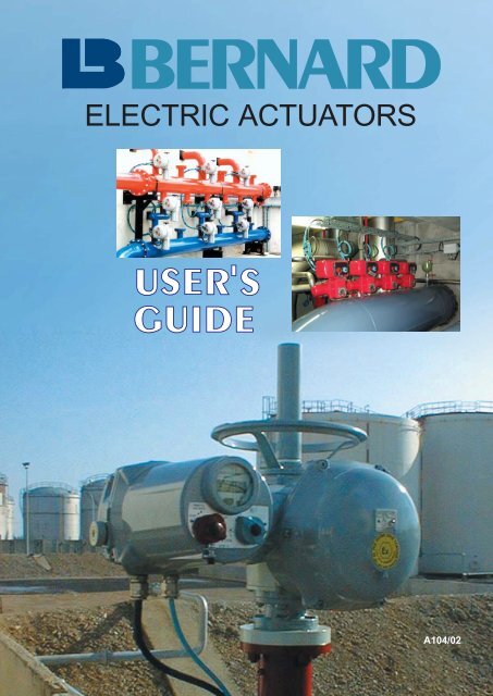
<strong>ELECTRIC</strong> <strong>ACTUATORS</strong><br />
A104/02
2<br />
USER’S<br />
GUIDE<br />
SUMMARY<br />
CHOOSING<br />
THE RANGE<br />
CHOOSING<br />
THE<br />
<strong>CO</strong>NTROL<br />
FIELDBUS<br />
p4 Analysis<br />
p6 Environment<br />
p8 Operation type<br />
p9 Fail safe<br />
p10 Choosing the range<br />
p12 Mechanical and electrical features<br />
p16 The possibilities<br />
p17 Comparison<br />
p18 Integral control<br />
p20 Signalling options<br />
p21 Communication by fieldbus
The electric actuator, initially designed to operate<br />
valves and dampers has now become a maintenance<br />
and control tool.<br />
The integration of the control elements directly inside<br />
the actuator provides for a command perfectly<br />
adapted to the various functions of the device.<br />
The data of its internal sensors are conveyed by a<br />
fieldbus, informing the users of the valve operating<br />
conditions and enabling remote modification of<br />
some parameters.<br />
The user can thus modify the operating parameters<br />
locally and without opening the covers, providing<br />
for a real “plug and play”.<br />
Ranges suited to the need<br />
Depending on the element to be driven, the electric<br />
actuator shall be designed so as to meet the requirements<br />
of its operating environment. Data such as<br />
the degree of water tightness, the desired explosion-proof<br />
protection and also the presence of certain<br />
corrosive agents must be perfectly known by<br />
the user and taken into account.<br />
Requirements can be of several types : for instance,<br />
electrical actuators intended for nuclear plants<br />
shall feature high resistance to earthquakes or<br />
extreme temperatures.<br />
Operating conditions are a key factor and the design<br />
itself depends on requirements such as the type<br />
of operation : on/off or modulating, the number of<br />
operations (3000 or 1 million) or the precision of<br />
positioning (low or high). With the L. BERNARD<br />
classification, users can easily define their needs.<br />
Moreover, a fail-safe system is available for the<br />
users, even with an electric actuator.<br />
Choice of control depends on process<br />
During installation, users can choose to integrate<br />
3<br />
USER’S<br />
GUIDE<br />
THE <strong>ELECTRIC</strong><br />
ACTUATOR<br />
the control boxes to the electric actuator or to<br />
remotely install them into control cabinets. A series<br />
of controls are proposed to the users on all ranges.<br />
The integral version, adapted or not to modulation<br />
provide for local or remote controls. The smart versions<br />
combine the advantages of the classic integral<br />
versions with the flexibility offered by the<br />
microprocessor : maintenance, automatic adjustment,<br />
etc.<br />
Communication by fieldbus is possible whatever<br />
the range or control selected.<br />
As the fieldbus is now available on a growing number<br />
of facilities, large volumes of data can be transferred<br />
while considerably reducing the on-site<br />
wiring costs. Several Bus interfaces are available<br />
whatever the electric actuator and its control.<br />
Thus, the choice of an electric actuator is critical as<br />
regards the reliability of the industrial process but<br />
also the optimum operation at commissioning as<br />
well as throughout the device lifetime.<br />
The L. BERNARD products have been designed to<br />
be tailored to the required needs with the best quality/cost<br />
combination. They are manufactured<br />
according to recognized quality standards :<br />
As the L. BERNARD products are constantly<br />
enhanced, please check the specifications when<br />
placing your orders.
4<br />
USER’S<br />
GUIDE<br />
CHOOSING<br />
THE RANGE<br />
Analysis<br />
Four questions to be asked for determining<br />
the most suited range :<br />
1. TYPE OF MOVEMENT OF THE DEVICE TO BE DRIVEN<br />
Type of device . . . . . . . . . . . . . . . . . . . . . . . . . . . . . . . . . Movement<br />
Butterfly valves . . . . . . . . . . . . . . . . . . . . . . . . . . . . . . . . . . Quarter-turn<br />
Ball and Plug valves . . . . . . . . . . . . . . . . . . . . . . . . . . . . . . Quarter-turn<br />
Dampers and louvers . . . . . . . . . . . . . . . . . . . . . . . . . . . . . Quarter-turn<br />
Globe valves . . . . . . . . . . . . . . . . . . . . . . . . . . . . . . . . . . . . Multiturn<br />
Pinch and diaphragm valves . . . . . . . . . . . . . . . . . . . . . . . . Multiturn<br />
Gate or knife valves . . . . . . . . . . . . . . . . . . . . . . . . . . . . . . Linear<br />
2. TYPE OF ENVIRONMENT<br />
Site of installation . . . . . . . . . . . . . . . . . . . . . . . . . . . . . . . Actuator enclosure protection<br />
Normal environment . . . . . . . . . . . . . . . . . . . . . . . . . . . . . . Watertight<br />
Hazardous areas . . . . . . . . . . . . . . . . . . . . . . . . . . . . . . . . Explosion proof<br />
Nuclear sites . . . . . . . . . . . . . . . . . . . . . . . . . . . . . . . . . . . Nuclear<br />
Corrosive atmosphere . . . . . . . . . . . . . . . . . . . . . . . . . . . . . Special
5<br />
USER’S<br />
GUIDE<br />
3. TYPE OF OPERATION OF THE DEVICE TO BE DRIVEN<br />
CHOOSING<br />
THE RANGE<br />
Analysis<br />
Type of operation . . . . . . . . . . . . . . . . . . . . . . . . . . . . . . . Actuator function<br />
Open or close the full stroke, . . . . . . . . . . . . . . . . . . . . . . . . On-Off<br />
on average 20 to 30 times/day.<br />
Select intermediate positions, Modulating<br />
with good precision (better than 2 %) . . . . . . . . . . . . . . . . . Class III<br />
on average 360 times/day.<br />
Select intermediate positions, Modulating<br />
with high precision (better than 1 %) . . . . . . . . . . . . . . . . . . Class II<br />
on a permanent basis every 2 or 3 seconds.<br />
Fast positioning Modulating<br />
with an excellent precision (0,5 % or better) . . . . . . . . . . . . Class I<br />
and continuous movement.<br />
4. SAFETY POSITION<br />
Safety requirement . . . . . . . . . . . . . . . . . . . . . . . . . . . . . Type of actuator<br />
In case of power supply failure,<br />
the valve can remain in the last position . . . . . . . . . . . . . . . Stay put<br />
without any danger.<br />
In case of control signal failure, Actuator with automatic<br />
the valve should move automatically . . . . . . . . . . . . . . . . . . emergency action<br />
to the safe position.<br />
In case of a complete power failure,<br />
the valve should move automatically . . . . . . . . . . . . . . . . . . Fail safe<br />
to the safety position.
6<br />
USER’S<br />
GUIDE<br />
CHOOSING<br />
THE RANGE<br />
Environment<br />
If the actuator is :<br />
Inside a building<br />
Outdoors under shelter<br />
Outdoors<br />
Risk of temporary submersion<br />
(less than 30 mn and less than 1 m deep)<br />
Risk of temporary submersion<br />
(time lapse and depth to be defined)<br />
On-shore<br />
Off-shore<br />
In case of special constraints :<br />
Hazardous areas<br />
Nuclear sites<br />
Corrosive environment<br />
(chemical products, alumina, etc, ...)<br />
Recommanded actuator protection<br />
Weatherproof IP 65 or NEMA 4<br />
Weatherproof IP 65 or NEMA 4<br />
+<br />
Weatherproof IP 67 or NEMA 4<br />
+ Epoxy paint +<br />
polyurethane finishing<br />
Weatherproof IP 67 or NEMA 6<br />
+ special paint +<br />
Weatherproof IP 68 or NEMA 6P<br />
+ special paint +<br />
Weatherproof IP 66 or NEMA 4X<br />
+ marine protection +<br />
Weatherproof IP 66 or NEMA 4X<br />
+ offshore protection +<br />
= Anti-condensation heater<br />
Explosion proof<br />
ATEX or NEMA<br />
Actuator qualification<br />
according to RCC-E and IEEE<br />
Special
The European directive 94/9/CE, applicable from<br />
the 30th of June 2003, states the conditions to be<br />
met by the equipment items for use under poten-<br />
GROUP I<br />
Underground<br />
parts of mines<br />
Our explosion proof products have been designed<br />
for use in GROUP II, Category 2 or 3 G (D) areas.<br />
These products shall, among other requirements,<br />
undergo a CE examination of the type corres-<br />
Equipment with electric<br />
connection in increased<br />
safety “e” (tight terminal<br />
box).<br />
The remaining parts of<br />
the electric equipment<br />
are in explosion-proof “d”<br />
enclosure.<br />
7<br />
9<br />
Hazardous areas<br />
EUROPEAN STANDARD ATEX<br />
GROUP II<br />
Other areas<br />
under explosible<br />
atmosphere<br />
I Combustible<br />
gases and<br />
vapours<br />
II Combustible<br />
dusts<br />
7<br />
USER’S<br />
GUIDE<br />
CHOOSING<br />
THE RANGE<br />
Environment<br />
tially explosive atmosphere.<br />
It classifies the installation areas according to<br />
groups and categories :<br />
CATEGORY 1 : Areas in which explosive atmospheres<br />
are present continuously or frequently.<br />
CATEGORY 2 : Areas in which explosive atmospheres<br />
are likely to occur.<br />
CATEGORY 3 :<br />
Areas in which explosive atmospheres<br />
are unlikely to occur or, if they do occur,<br />
are likely to do so only infrequently or for<br />
short period only.<br />
Protection by flame-proof<br />
enclosure. Connection is<br />
achieved inside the<br />
enclosure. Enclosure is<br />
resistant to internal<br />
explosion without flame<br />
path.<br />
Group B : Hydrogen<br />
Group C : Ether, Ethylene,...<br />
Group D : Butane, Propane,...<br />
Group E : Metal dust<br />
Group F : Coal dust<br />
Group G : Flour and other<br />
dusts<br />
G/ gas or vapour<br />
D/ dust<br />
ponding to the sections of the standards CENELEC<br />
EN 50014, 50018, 50019 applicable for each<br />
product :<br />
EEx (e) d II C T6<br />
Explosionproof actuator<br />
EEx ed<br />
NORTH-AMERICAN STANDARDS : NEMA RATINGS<br />
Group I : Equipment for<br />
underground mining.<br />
Group II : Equipment for<br />
explosive atmosphere<br />
other than mining.<br />
A : butane, propane,...<br />
B : ethylene,...<br />
C : hydrogen, acetylene<br />
1 : normal<br />
conditions<br />
2 : abnormal<br />
conditions<br />
Maximum surface<br />
temperature<br />
T1 = 450 °C<br />
T2 = 300 °C<br />
T3 = 200 °C<br />
T4 = 135 °C<br />
T5 = 100 °C<br />
T6 = 85 °C<br />
Explosionproof actuator<br />
EEx d or NEMA 7 or NEMA 9<br />
NEMA Class Group Division T4<br />
Maximum<br />
surface<br />
temperature<br />
T1 = 842 °F<br />
T2 = 572 °F<br />
T3 = 392 °F<br />
T4 = 275 °F<br />
T5 = 212 °F<br />
T6 = 185 °F
8<br />
USER’S<br />
GUIDE<br />
CHOOSING<br />
THE RANGE<br />
Operation type<br />
The requirements of the process determine the<br />
characteristics of an actuator.<br />
A modulating actuator has to be fully adapted to<br />
the duty given by the modulating loop. According to<br />
the duty or the function frequency, the actuator<br />
technology and its cost will be different.<br />
Within the range of actuators produced by L.<br />
BERNARD, the users can choose among four<br />
types of operation.<br />
ON/OFF<br />
● The actuator has been designed to operate from<br />
an extreme position to another with intermediate<br />
positions, if needed.<br />
● The motor is capable of starting 360 times per<br />
hour with a duty cycle of 30% and an ambient<br />
temperature under 40°C. This rate decreases<br />
when temperature rises.<br />
● The actuator is capable of performing approximately<br />
15 to 20 operations a day.<br />
CLASS III MODULATING<br />
Open<br />
Close<br />
CLASS III<br />
Time<br />
● The actuator is able to reach an intermediate<br />
position with a sufficient precision (better than<br />
2%).<br />
● The motor is able to start 1200 times per hour<br />
with a duty cycle of 50%, as to say a start every<br />
3 seconds. This starting frequency allows the<br />
process to stabilise a position, but shall not be<br />
kept permanently.<br />
● A class III actuator is designed for an average of<br />
360 changes of position a day.<br />
Technology : A class III actuator is selected in the<br />
On/Off actuators range.<br />
CLASS II MODULATING<br />
Open<br />
Close<br />
● The actuator is able to reach an intermediate<br />
position with a good precision (better than 1%).<br />
● The motor is able to start 1800 times per hour<br />
with a duty cycle of 100%.<br />
● A class II actuator is designed to move every 2 or<br />
3 seconds.<br />
Technology : Actuator with high mechanical efficiency,<br />
special modulating motor, solid state relay<br />
control.<br />
CLASS I MODULATING<br />
Open<br />
Close<br />
CLASS II<br />
CLASS I<br />
Time<br />
Time<br />
● The actuator is able to reach an intermediate<br />
position with a precision of 0,5% or better.<br />
● The actuator can move the valve, full stroke, very<br />
quickly.<br />
● A class I actuator is designed to move permanently.<br />
Technology : Actuator with high mechanical efficiency,<br />
brushless electric motor with speed regulation.
The fail-safe devices are used to provide for the<br />
safety of the fixtures when the external power source<br />
to the actuator is no longer supplied.<br />
APPLICATION FIELDS<br />
They include :<br />
● All the fields where the interruption of the actuator<br />
power requires the automatic switching of the<br />
driven device to a safe postion.<br />
● All the facilities where the risks are such that driving<br />
the device to its safe position must be possible<br />
at any time even in the absence of external<br />
power.<br />
Example : storage and distribution of gas and dangerous<br />
liquids, fire protection systems, protection<br />
of chemical facilities, air conditioning and ventilation<br />
of hazardours areas.<br />
IMPORTANT FUNCTIONS<br />
ACTUATOR WITH RETURN SPRING<br />
The actuator operates under normal conditions,<br />
actuated by an electric motor, which simultaneously<br />
drives the device to be motorised and a high<br />
resistance spiral spring.<br />
What is FAIL SAFE ?<br />
A solenoid which is<br />
continuously power<br />
supplied releases the<br />
device + spring assembly<br />
when its power supply<br />
is interrupted, for<br />
whatever reason.<br />
When power is restored,<br />
the actuator automatically<br />
comes back to<br />
its position, according to<br />
the commands received.<br />
9<br />
USER’S<br />
GUIDE<br />
CHOOSING<br />
THE RANGE<br />
Fail safe<br />
ACTUATOR WITH INTEGRATED BATTERY<br />
The actuator is a standard D.C. equipment item, to<br />
which is added an integrated control card and a<br />
battery. It is operated under normal conditions with<br />
an external power supply which charges the battery<br />
at the same time.<br />
In case of short-cut, the<br />
actuator automatically<br />
returns to its safe position<br />
with the help of the<br />
integrated battey.<br />
Once the power is restored,<br />
the actuator can<br />
operate under normal<br />
conditions and the battery<br />
recharges.<br />
The activation of an emergency signal triggers the immediate opening or closing of the backup device<br />
without the need of any external power source.<br />
This signal can be activated following :<br />
● an ABNORMAL EVENT (fire, overflow, ...)<br />
● AUTOMATIC <strong>CO</strong>NTROL<br />
● OPERATOR’S ACTION<br />
● or the ABSENCE OF POWER
ENVIRONMENT<br />
10<br />
USER’S<br />
GUIDE<br />
CHOOSING<br />
THE RANGE<br />
WITHOUT<br />
FAIL SAFE<br />
POSITION<br />
STANDARD<br />
EXPLOSION<br />
PROOF<br />
OPERATION<br />
NUCLEAR<br />
ON / OFF<br />
&<br />
MODULATING<br />
CLASS III<br />
MODULATING<br />
CLASSES II & I<br />
ON / OFF<br />
&<br />
MODULATING<br />
CLASS III<br />
MODULATING<br />
CLASS II<br />
TYPE OF MOVEMENT<br />
QUARTER-TURN<br />
Torque Torque MULTITURN LINEAR<br />
< 4 000 N.m. > 4 000 N.m.<br />
SD<br />
Catalogue<br />
Modulating<br />
Catalogue<br />
SD<br />
Catalogue<br />
Modulating<br />
Catalogue<br />
ST<br />
Catalogue<br />
Modulating<br />
Catalogue<br />
ST<br />
Catalogue<br />
Modulating<br />
Catalogue<br />
Nuclear Nuclear<br />
Catalogue<br />
ST<br />
Catalogue<br />
Modulating<br />
Catalogue<br />
ST<br />
Catalogue<br />
Modulating<br />
Catalogue<br />
ST ST<br />
Catalogue<br />
Modulating<br />
Catalogue<br />
ST<br />
Catalogue<br />
Modulating<br />
Modulating<br />
Catalogue
ENVIRONMENT<br />
WITH<br />
FAIL SAFE<br />
POSITION<br />
STANDARD<br />
EXPLOSION<br />
PROOF<br />
OPERATION<br />
ON / OFF<br />
MODULATING<br />
CLASS III<br />
ON / OFF<br />
MODULATING<br />
CLASS III<br />
11<br />
USER’S<br />
GUIDE<br />
TYPE OF MOVEMENT<br />
CHOOSING<br />
THE RANGE<br />
QUARTER-TURN LINEAR<br />
FQ<br />
Catalogue<br />
Modulating<br />
Catalogue<br />
FQ<br />
Catalogue<br />
Modulating<br />
Catalogue<br />
FL<br />
Catalogue<br />
Modulating<br />
Catalogue<br />
FL<br />
Catalogue<br />
Modulating<br />
Catalogue
12<br />
USER’S<br />
GUIDE<br />
CHOOSING<br />
THE RANGE<br />
Mechanical and<br />
electrical features<br />
QUARTER-TURN<br />
Often installed in enclosed<br />
spaces, the quarter-turn electrical<br />
actuator must be as<br />
compact as possible. The irreversibility<br />
of the actuator is<br />
necessary in order not to supply<br />
power on a permanent<br />
basis even when the device is shutdown and to<br />
guarantee that the valve stays in the required position.<br />
Moreover, for operation in environments generating<br />
strong vibrations, it is essential that the gear<br />
modules be well sized for a better resistance.<br />
Lastly, even if the travel limitation provides for the<br />
stop of the actuator, it shall also be equipped with<br />
mechanical stops in order to protect the driven<br />
device in the case of a manual operation with the<br />
handwheel.<br />
Our choice : – compact<br />
– self-locking with a worm/<br />
quadrant gear<br />
– large gear modules<br />
– adjustable mechanical stops<br />
MULTITURN<br />
The multiturn electric actuators<br />
can either be mounted<br />
directly or with additional<br />
reduction gears. In order to<br />
meet the requirements of<br />
their numerous functions, a<br />
wide range of torque and speed values are required.<br />
They must also offer full irreversibility, whatever<br />
the operating speed, in order to maintain the<br />
valve in position. For the user’s safety, it is highly<br />
recommended that the handwheel does not rotate;<br />
priority must also be given to the electric control,<br />
without clutch system for high torque actuators.<br />
Geardrives<br />
Our choice : – wide range of speed and<br />
torque values<br />
– easy-to-use<br />
– self-locking at all speed<br />
– non-rotating handwheel with<br />
priority to electric control<br />
For high torque values, our SERMATIC system<br />
combined with a differential gear on the output<br />
shaft enables driving either by a motor or a<br />
handwheel without any clutch system, providing for<br />
considerable enhancement and simplification of the<br />
geardrive.<br />
MODULATING<br />
As regards modulation, the<br />
most important criteria are<br />
precision and long-term availability.<br />
The use of small motors<br />
considerably reduces the<br />
inertia.<br />
Furthermore, a high reduction gear directly installed<br />
at the motor output provides for a better control<br />
of the actuator.<br />
Lastly, to reduce the play in the handwheel mechanism<br />
to a minimum, the use of a system with<br />
manual priority is better adapted.<br />
Our choice : – precision with small motors<br />
– quality / price ratio<br />
– long term availability<br />
thanks to our epicycloidal<br />
gear system<br />
LINEAR<br />
The L. BERNARD range of linear actuators is<br />
obtained by adding a movement conversion system<br />
to the multiturn actuator.
Electric motors<br />
The choice of an operation type determines the<br />
selection of a motor for each function.<br />
The IEC 34 recommendation has defined several<br />
types of actuator standard duty cycles for determining<br />
the use conditions of an electric motor.<br />
IEC 34 STANDARD<br />
S1 : Continuous duty<br />
Operation with constant load over a sufficient duration for reaching<br />
a thermal equilibrium.<br />
S2 : Short time duty<br />
Short time operation, total cooling between each start.<br />
S3 : Intermittent periodic duty<br />
The starting current has no significant effect on temperature rise.<br />
To be followed by the max. operating time.<br />
S4 : Intermittent duty with starting<br />
Repetition of cycles including :<br />
● starting period D,<br />
● period of constant speed N,<br />
● rest period R.<br />
MODULATING<br />
To be followed by the duty factor in %, as well as the number of starts per hour.<br />
Our choice : S4<br />
13<br />
USER’S<br />
GUIDE<br />
CHOOSING<br />
THE RANGE<br />
Mechanical and<br />
electrical features<br />
The only duty cycle corresponding to the required<br />
actuator operation is S4. Its parameters will be<br />
optimised to fit each application.<br />
DUTY OBJECTIVE TYPE OF MOTOR TYPE OF DUTY FREQUENCY<br />
● Operating time Asynchronous AC : 360 starts/hour<br />
ON / OFF ● Successive starts 3 phase or single phase S4 - 30 % DC : 60 starts/hour<br />
Direct current<br />
● Operating time Asynchronous<br />
CLASS III ● Repetition of starts 3 phase or single phase S4 - 50 % 1 200 starts/hour<br />
(Direct current possible)<br />
● High number Asynchronous 3 phase<br />
CLASS II l of starts (Single phase possible) S4 - 100 % 1 800 starts/hour<br />
● Low inertia<br />
● Speed variation Brushless direct current<br />
CLASS I ● Continuous operation with servo drive S4 - 100 % NO LIMITS<br />
General technical data<br />
of AC motors<br />
➜ SQUIRREL CAGE type<br />
➜ Insulation CLASS F<br />
➜ Watertight enclosure<br />
➜ Built-in thermal protection<br />
General technical data<br />
of DC motors<br />
Applicable only for ON / OFF and Class III duty<br />
➜ <strong>CO</strong>MPOUND type winding<br />
➜ Insulation CLASS F<br />
➜ Watertight enclosure<br />
➜ Built-in thermal protection
14<br />
USER’S<br />
GUIDE<br />
CHOOSING<br />
THE RANGE<br />
Mechanical and<br />
electrical features<br />
Depending on the markets and types of facilities,<br />
the features of the emergency manual control, one<br />
of the key functions of the actuator, can be very different.<br />
However, several features are of prime significance,<br />
mainly :<br />
● a well adapted gear ratio, in order to limit the<br />
number of turns required to operate the valve,<br />
● a reliable use safety in order not to endanger the<br />
users,<br />
● full availability.<br />
Manual control with electrical priority is required in<br />
most of the technical specifications. However, the<br />
following 2 principles must be obeyed :<br />
● it must be possible to operate the manual control<br />
in any case,<br />
● the number of turns on the handwheel must not<br />
be too significant.<br />
<strong>CO</strong>RRECT SIZED HANDWHEEL GEARING<br />
SAFETY<br />
Manual operation<br />
Example 1 : On a pressurised<br />
steam circuit, the valve closes<br />
using the torque limiter. When<br />
the torque is high, the use of a<br />
dog coupling is not safe enough<br />
as the force to be applied to the<br />
clutch lever for switching to<br />
manual mode is high.<br />
Example 2 : Depending on the technology used,<br />
the number of turns on the handwheel can vary<br />
from 30 to more than 500 turns, in order to drive a<br />
DN500 quarter-turn valve with a torque of approximately<br />
2500 Nm. Thus, the stacking of reduction<br />
gears can inhibit the safety function of the manual<br />
control.<br />
In conclusion, there is not one solution for all the<br />
applications but different techniques adapted to the<br />
real needs.<br />
QUARTER-TURN MULTITURN<br />
Type No. of turns Torque Ratio<br />
OA 9 to 21 < 60 Nm 1/1<br />
AS < 800 Nm 8 to 11 < 300 Nm 1/2<br />
AS > 1 000 Nm 50 to 216 > 300 Nm 1/*<br />
BS 14 * according to torque<br />
UX 8 to 11<br />
QUARTER-TURN<br />
MULTITURN<br />
Modulating Classes II, I<br />
Full handwheel rotating at low speed.<br />
Non rotating handwheel, with electrical priority, for high torque values.<br />
Non rotating handwheel, with electrical priority.<br />
Non rotating handwheel, motor automatically switched off during manual operation.
The use of a patented cam holder system has the<br />
following advantages :<br />
● easy setting, without any special tools<br />
● vibration proof<br />
● precise proportional indication<br />
The large diameter cam block includes four cams<br />
which can be adjusted separately on the overall<br />
travel. By simply pushing the adjusting slot of a<br />
L. BERNARD design of torque limiters is of proven<br />
technical superiority, offering :<br />
● full reliability,<br />
● ease of adjustment,<br />
● high precision,<br />
Travel limitation<br />
The torque is always measured on non moving<br />
parts, thus avoiding risk of wear.<br />
In the case of kinematics chains with planetary<br />
gear drives, the torque is measured on the external<br />
crown by helical springs.<br />
The torque is no longer applied when the motor is<br />
stopped, thus releasing the mechanical parts. If the<br />
Torque limiters<br />
15<br />
USER’S<br />
GUIDE<br />
CHOOSING<br />
THE RANGE<br />
Mechanical and<br />
electrical features<br />
cam, the latter is released and can be freely positioned.<br />
When the adjusting slot is released, the<br />
cam is automatically locked. As no screw tightening<br />
is needed, the system is not sensitive to vibrations.<br />
In smart versions, the cam block is replaced by an<br />
absolute position sensor with optical absolute<br />
encoder.<br />
signal must be maintained, electrical or mechanical<br />
memorisation is available as an option.<br />
In the case of differential chains, the torque is<br />
higher and will be measured directly on the actuator<br />
shaft, at the differential manual end.<br />
On the ST range actuators, the torque limiter is<br />
always memorised mechanically and a proportional<br />
torque adjustment system which can be adjusted<br />
locally or remotely is available, depending on<br />
the control versions adopted.<br />
Note : the memorised torque limiter function is<br />
always included in the versions with built-in electronics,<br />
such as INTEGRAL+, POSIGAM+, MODU-<br />
GAM+ and INTELLI+.
16<br />
USER’S<br />
GUIDE<br />
CHOOSING<br />
THE <strong>CO</strong>NTROL<br />
The possibilities<br />
Two main types of commands are available :<br />
● fieldbus command<br />
● wire-by-wire command<br />
VERSION <strong>CO</strong>NTROL<br />
STANDARD<br />
The control unit is external to<br />
the actuator. It receives information<br />
from the actuator and<br />
directly controls the electric<br />
motor.<br />
CLASSIC<br />
The control unit and power<br />
contactors are integrated to<br />
the actuator. It executes the<br />
orders received by the supervisor.<br />
DIGITAL<br />
The control unit is digital and<br />
integrated to the actuator. In<br />
addition to the standard<br />
control and monitoring functions,<br />
it provides for numerous<br />
adjustment, monitoring<br />
and maintenance functions,<br />
locally or remotely.<br />
ON / OFF<br />
The travel limitation and<br />
torque limiter contacts transmit<br />
the information to the<br />
external control system which<br />
controls the motor.<br />
PROPORTIONAL<br />
In addition to the contacts, the<br />
position transmitter indicates<br />
the position of the valve and<br />
provides for proportional<br />
control managed by users.<br />
ON / OFF<br />
The information from the<br />
contacts are directly processed<br />
by the integrated control<br />
unit and relayed to the outside<br />
for signalling.<br />
PROPORTIONAL<br />
The position transmitter<br />
directly informs the integrated<br />
positioner, providing for a proportional<br />
control managed by<br />
the actuator.<br />
The position and torque sensors<br />
are absolute, digital and<br />
proportional. Numerous<br />
control variants are possible<br />
and can be programmed from<br />
the outside of the actuator.<br />
All the L. BERNARD ranges are compatible with<br />
both options. The various FIELDBUS interfaces<br />
are listed at the end of this guide.<br />
The user can choose among three versions, two of<br />
them being integral.<br />
<strong>CO</strong>MMANDS<br />
Wire-by-wire Fieldbus<br />
not<br />
applicable
REMOTE<br />
<strong>CO</strong>NTROL<br />
LOCAL<br />
<strong>CO</strong>NTROL<br />
INTERNAL<br />
PROTECTION<br />
SIGNALLING<br />
SETTING AND<br />
<strong>CO</strong>MMISSIONING<br />
MONITORING<br />
AND MAINTENANCE<br />
■ Standard<br />
Standard and “smart” controls<br />
17<br />
USER’S<br />
GUIDE<br />
CHOOSING<br />
THE <strong>CO</strong>NTROL<br />
Comparison<br />
Standard integrated Digital integrated<br />
control control<br />
Pulse command ■ ■<br />
Maintained signal ■ ■<br />
Proportional ■ ■<br />
Positioner version Positioner version<br />
ESD ■ ■<br />
Auxiliary ■ 2 commands,<br />
Local command inhibition 9 possibilities<br />
Timer Option ■<br />
Pad-lockable selectors ■ ■<br />
Digital text display – ■<br />
Power indication – ■<br />
Timer Option ■<br />
Fuses ■ ■<br />
Automatic phase monitoring ■ ■<br />
Motor thermal switch ■ ■<br />
Torque limiter memory ■ ■<br />
Amount of information available 16 23<br />
Amount of information to be selected<br />
4<br />
+ 3 in option<br />
4<br />
+ 3 in option<br />
Fault monitoring relay ■ ■<br />
Number of listed faults 8 12<br />
Remote position signalling Option Option<br />
Configuration access Intrusive Non intrusive<br />
Configuration means Jumpers By external selectors<br />
Or with laptop<br />
Or through fieldbus<br />
Torque position setting<br />
Mechanical Digital<br />
Type of setting<br />
Download of complete setting<br />
On position On position<br />
On torque On automatic torque<br />
– With laptop<br />
Or through fieldbus<br />
Monitoring of internal components – ■<br />
Monitoring of performance – ■<br />
Monitoring of torque values<br />
– ■<br />
Transfer of torque /<br />
position curves – ■<br />
Actuator activity monitoring<br />
- Total operating time – ■<br />
- Number of starts – ■<br />
- Handwheel action – ■
18<br />
USER’S<br />
GUIDE<br />
CHOOSING<br />
THE <strong>CO</strong>NTROL<br />
Integral control<br />
Standard actuator including travel and torque limit<br />
switches requires additional electrical equipment to<br />
be integrated into a process, this involves extra<br />
costs for the study, the setting and the commissioning.<br />
L. BERNARD offers a range of actuators with<br />
integrated control enabling the engineering to<br />
benefit from a simple and standardised command<br />
interface.<br />
Start-up is made easier by the presence of local<br />
controls and can be activated by simply connecting<br />
power, thus saving time.<br />
The functions can be easily configured on the<br />
actuator for on-site installation at lower costs.<br />
“Minigral+” “Minigam+”<br />
This compact electronic board has the<br />
ability to control single-phase actuators<br />
with a power less than 300 W.<br />
● MINIGRAL+ and MINIGAM+ common functions :<br />
- Stop on travel or torque limit switches (prohibits<br />
restarting)<br />
- Open / Close signalling<br />
- Configurable rotational direction<br />
● ON / OFF command : MINIGRAL+ version<br />
- Open / Close command<br />
- Power, command and signalling using 1 wire<br />
● Proportional command : MINIGAM+ version<br />
- Input signal 4-20mA, 0-20mA, 0-10V, 2-10V<br />
- Remote position signal 4-20mA, 0-20mA, 0-10V,<br />
2-10V<br />
● Fault monitoring relay option<br />
CLASSIC INTEGRAL <strong>CO</strong>NTROL<br />
For small single phase<br />
actuators<br />
DIGITAL INTEGRAL <strong>CO</strong>NTROL<br />
Non intrusive<br />
configuration + diagnostic<br />
and maintenance<br />
“Integral+” “Posigam+”<br />
“Modugam+”<br />
For all powers<br />
configurable commands<br />
and signalling<br />
This control offers a large choice of<br />
functions.<br />
● Functions common to 3 versions :<br />
- Stop on travel or torque limit switches (prohibits<br />
restarting)<br />
- Signalling by 4 configurable relays<br />
- Configurable fault relay<br />
- Automatic phase monitoring<br />
- Configurable rotational direction<br />
● ON / OFF control : INTEGRAL+ version<br />
- Open / close control by contact or voltage<br />
- Local control<br />
- Emergency control and local control inhibition
● Proportional control : POSIGAM+ and MODU-<br />
GAM+ versions<br />
The POSIGAM+ version is designed to be installed<br />
on Class III modulating actuators, and the<br />
MODUGAM+ version on the Class II actuators.<br />
- Input signal 4-20mA, 0-20mA, 0-10V, 2-10V<br />
- remote position signal 4-20mA, 0-20mA, 0-10V<br />
- Open / close control by contact or voltage<br />
- Emergency control and selection of proportional<br />
control or ON / OFF<br />
● Options :<br />
- Signalling by 3 additional relays<br />
- Inertia rate meter (to prevent pressure surge)<br />
- Local control<br />
- Local signalling indicator lights<br />
- Remote position signal<br />
● Proportional control : PRECIGAM version<br />
In order to meet the requirements of modulating<br />
Class I regarding extreme operating conditions, the<br />
PRECIGAM version is available within the L.<br />
BERNARD range.<br />
Associated with a Class I actuator, the PRECIGAM<br />
unit enables fast and precise positioning.<br />
With this advanced technology, accelerations,<br />
speed and torque with servo control of a brushless<br />
DC motor with Samarium Cobalt magnets can now<br />
be controlled.<br />
The power module uses the pulse with modulating<br />
technique for an optimum output.<br />
“Intelli+”<br />
19<br />
USER’S<br />
GUIDE<br />
CHOOSING<br />
THE <strong>CO</strong>NTROL<br />
Integral control<br />
The INTELLI+ control is used for<br />
diagnostic and preventative maintenance.<br />
INTELLI+ performs real time<br />
monitoring of the actuator and its<br />
performance levels through specific sensors and a<br />
precise processing algorithm.<br />
Numerous functions are available to the users in<br />
INTELLI+ for helping them in their diagnostics and<br />
for programming the maintenance of their valves.<br />
INTELLI+ also guarantees to the users an optimum<br />
availability of their industrial facilities.<br />
● Main functions :<br />
- Open / close control by contact or voltage<br />
- 2 configurable auxiliary controls (example :<br />
emergency control)<br />
- Signalling by 4 configurable relays<br />
- Configurable fault monitoring relay<br />
- Automatic phase monitoring<br />
- Adjustment and setting without any tools and without<br />
opening any cover<br />
- Dialogue with the user by multilingual menus<br />
- Local indicator lights and back lit display<br />
- Position monitoring by digital absolute encoder<br />
- Monitoring of the real torque transmitted to the valve<br />
by digital absolute encoder<br />
- Recording of the max. torque values for each<br />
operating zone<br />
- Increase of the operating time (to prevent pressure<br />
surge)<br />
- Auto-diagnostic of the actuator and display of the<br />
alarms<br />
- Recording of the actuator activity<br />
(number of starts, operating time, activity over the last<br />
12 hours)<br />
- Communication for Laptop, for diagnostic, configuration<br />
and recording<br />
● Options :<br />
- Signalling by 3 additional relays<br />
- Remote position and torque signal<br />
- Proportional control with analogue interface :<br />
=> input signal 4-20mA, 0-20mA, 0-10V, 2-10V<br />
=> remote position signal 4-20mA, 0-20mA, 0-10V,<br />
2-10V
20<br />
USER’S<br />
GUIDE<br />
CHOOSING<br />
THE <strong>CO</strong>NTROL<br />
Signalling options<br />
<strong>CO</strong>NTACTS<br />
Standard selector limit switches<br />
● DC rated :<br />
Voltage Resistive load Inductive load<br />
24 V 16 V 5 A<br />
48 V 2,5 A 1,2 A<br />
127 V 0,8 A 0,35 A<br />
230 V 0,6 A 2,2 A<br />
● AC rated :<br />
Voltage Resistive load Inductive load<br />
Up to 250 V 16 V 2 A<br />
● Optional :<br />
– DPDT (selector switch without common point)<br />
– Nitrogen filling<br />
– Inductive<br />
– Watertight<br />
– Explosion proof<br />
POTENTIOMETER<br />
Valve position image, the remote position signal must not be<br />
underestimated.<br />
● Model 200 for ON / OFF or Class III actuators<br />
Power 1 Watt - Plastic track - 1 Kohm value -<br />
Others on request - Single or double type.<br />
● Model 210 for actuators of Class II or Class I<br />
Power 2 Watts - Plastic track, nearly infinite resolution<br />
- 1 Kohm value - Single or double type.<br />
TAM : ELECTRONIC POSITION TRANSMITTER<br />
The TAM transmitter remotely sends the position<br />
of the driven device, via a 4-20 mA or 0-20 mA<br />
current signal, irrespective of the line length and<br />
with protection against interference. The TAM<br />
includes a 1 Kohm potentiometer associated with<br />
an electronic module.<br />
● Technical data :<br />
– Supply voltage : 12 to 32 V DC (rectified, filtered<br />
or stabilised)<br />
– Max. admissible load : 750 Ohm at 24 V<br />
– 2 wire connection : 4-20 mA signal<br />
– 3 or 4 wire connection : 4-20 mA or 0-20 mA<br />
signal<br />
– Linearity : 0,5 %<br />
– Permitted temperature acceptance : -40°C to<br />
+70°C<br />
TIN : <strong>CO</strong>NTACTLESS POSITION TRANSMITTER<br />
As the TAM, the output signal of the TIN transmitter<br />
is equal to 4-20 mA or 0-20 mA. The inductive<br />
type sensor has the advantage of being unaffected<br />
by contact wear.<br />
● Technical data :<br />
– Supply voltage : 18 to 33 V DC (rectified, filtered<br />
or stabilised)<br />
– Max. admissible load : 600 Ohm<br />
– 2 wire connection : 4-20 mA signal<br />
– 3 or 4 wire connection : 4-20 mA or 0-20 mA<br />
signal<br />
– Linearity : 0,5 %<br />
– Permitted temperature : -10°C to +70°C
The fieldbus is the mean commonly used for<br />
exchanging information and commands with several<br />
actuators or sensors over a single electrical line.<br />
Each actuator requires an individual power supply<br />
and a communication line which, in the case of the<br />
fieldbus, is common to a set of actuators.<br />
The signal is encoded and an address is assigned<br />
to each actuator. Therefore, each actuator can<br />
identify those commands which are intended for it<br />
and the data transmitted by the actuator can be<br />
identified.<br />
The advantage of the fieldbus connection is, on the<br />
one hand, that several actuators can be connected<br />
over the same line and on the other, that the<br />
amount of data transmitted by each actuator can<br />
be increased without impacting wiring costs.<br />
A fieldbus which establishes connection for several<br />
actuators over a single line is distinct from an encoded<br />
4-20 mA system which is capable of carrying<br />
data superimposed over a 4-20 mA signal for a<br />
single actuator or sensor.<br />
A WIDE RANGE OF FIELDBUS SYSTEMS<br />
As a wide range of fieldbus systems exist, an<br />
actuator can only connect to a bus line if it is equipped<br />
with the fieldbus specific interface. There are<br />
“proprietary” systems, where a single manufactuer<br />
supplies the necessary interfaces, and “open” systems<br />
where various manufacturers can supply<br />
interfaces.<br />
With regard to “proprietary” systems, L. BERNARD<br />
offers the DUPLINE system, branded DS200.<br />
Although proprietary, this system is not L. BER-<br />
NARD-specific, as the manufacturer is Carlo<br />
Gavazzi. The user can therefore procure additional<br />
21<br />
USER’S<br />
GUIDE<br />
<strong>CO</strong>MMUNICATION<br />
BY FIELDBUS<br />
interfaces directly from Carlo Gavazzi, and is therefore<br />
not dependant on the actuator supplier.<br />
A “proprietary” system always includes the actuators<br />
and their bus interface, as well as the bus<br />
controller located at the line head-end, used for the<br />
dialogue with the PLC which controls the process.<br />
Communication with the PLC also uses a bus<br />
sytem. In general MODBUS is used.<br />
In the electric actuator domain, “open” systems<br />
mainly include :<br />
● PROFIBUS<br />
● MODBUS<br />
● FIELDBUS FOUNDATION<br />
With an “open” system, the actuator or sensor supplier<br />
usually limits its offer to the equipment equipped<br />
with the bus interface. The bus controller is<br />
generally integrated to an extension of the PLC.
22<br />
USER’S<br />
GUIDE<br />
<strong>CO</strong>MMUNICATION<br />
BY FIELDBUS<br />
PROFIBUS DP FIELDBUS<br />
The complete range of L. BERNARD actuators can<br />
be equipped with the PROFIBUS DP fieldbus interface.<br />
(Caution : a PROFIBUS DP interface can not<br />
be connected to a PROFIBUS FMS or PROFIBUS<br />
PA system).<br />
Each actuator is offered as an integral version,<br />
meaning it comes complete with contractors and is<br />
handled by an electronic board. This part may<br />
come as a separate unit. Both integral versions of<br />
the L. BERNARD range can be used : INTE-<br />
GRAL+ or INTELLI+, with the addition of the<br />
“PROFIBUS DP 32 I/O” interface for the INTE-<br />
GRAL or the “PROFIBUS DP data transfer” interface<br />
for the INTELLI+.<br />
A PROFIBUS line can control up to 30 actuators.<br />
Extra line repeaters are required to increase the<br />
number of actuators connected to a given line. The<br />
maximum line distance is 1.2 km, and more with<br />
repeaters.<br />
Only the actuator is supplied with its PROFIBUS<br />
DP interface. This actuator can connect to any<br />
PROFIBUS DP fieldbus even if other units are<br />
connected. The only requirement is not to exceed<br />
the number of connection points which is 30 max.<br />
Each actuator or sensor counts as a connection<br />
point, regardless of the amount of data transmitted.<br />
Automate<br />
Modbus RTU<br />
Dupline Master<br />
Module<br />
Modbus RTU<br />
MODBUS RTU FIELDBUS<br />
Actuators of the L. BERNARD range equipped with<br />
the INTELLI+ command can accomodate the<br />
MODBUS interface.<br />
A MODBUS line can control up to 30 actuators.<br />
Extra line repeaters are required to increase the<br />
number of actuators connected to a given line.<br />
Only the actuator is supplied with its MODBUS<br />
interface. This actuator can connect to any MOD-<br />
BUS RTU fieldbus even if other units are connected.<br />
The only requirement is not to exceed the<br />
number of connection points which is 30 max.<br />
Each actuator or sensor counts a a connection<br />
point, regardless of the amount of data transmitted.<br />
MODBUS RTU FIELDBUS FOR ACTUATOR<br />
AND DUPLINE FIELDBUS<br />
Actuators directly equipped for MODBUS operation<br />
can be associated on a given MODBUS line as<br />
described above with the DUPLINE MASTER<br />
MODULE or DS200 fieldbus as communication<br />
from the PLC is in both cases over the MODBUS.<br />
Dupline
This configuration offers the advantage of providing<br />
a highly cost-effective link for part of the actuators<br />
(connected to the DUPLINE sytstem) while some<br />
actuators direclty connected to MODBUS transmit<br />
all the data useful for monitoring the equipment and<br />
preventative maintenance.<br />
DEVICENET FIELDBUS<br />
Actuators of the L. BERNARD range equipped with<br />
the INTELLI+ command can accommodate the<br />
DEVICENET interface.<br />
A DEVICENET line can control up to 63 actuators.<br />
Only the actuator is supplied with its DEVICENET<br />
interface. This actuator can connect to any DEVI-<br />
CENET fieldbus even if other units are connected.<br />
The only requirement is not to exceed the number<br />
of connection points which is 64 max. Each actuator<br />
or sensor counts as a connection point, regardless<br />
of the amount of data transmitted.<br />
Up to 10 km length without<br />
loss of performance<br />
Up to 20 actuators<br />
per line<br />
Up to 16 lines starts<br />
DUPLINE FIELDBUS<br />
23<br />
USER’S<br />
GUIDE<br />
<strong>CO</strong>MMUNICATION<br />
BY FIELDBUS<br />
The complete range of L. BERNARD actuators can<br />
be equipped with the DUPLINE fieldbus interface.<br />
Each actuator is offered as an integral version,<br />
meaning it comes complete with contactors and is<br />
handled by an electronic board. This part may<br />
come as a separate unit.<br />
Both integral versions of the L. BERNARD range<br />
can be used : INTEGRAL+ or INTELLI+, with the<br />
addition of the “DS200” interface for the DUPLINE<br />
system. A bus controller, installed at the line headend,<br />
is supplied to control the assembly.<br />
Communication with the PLC is via MODBUS.<br />
Two systems are available. A single version is<br />
used to control a line of 31 actuators from the<br />
DUPLINE MASTER MODULE, or a redundant version<br />
from the DS200 <strong>CO</strong>NTROLLER, used to<br />
control up to 320 actuators, i.e. 20 actuators per<br />
line. The maximum line distance is 10 km.<br />
Pressostat<br />
Local control box<br />
PC<br />
PLC<br />
Pump<br />
Electro-valve
AT YOUR SERVICE<br />
OVER THE WORLD<br />
AUSTRALIA<br />
PEGLER BEA<strong>CO</strong>N Autralia Pty Ltd + 61 2 98 41 23 45<br />
25 South Street Rydalmere + 61 2 96 84 64 39<br />
NSW 2116 AUSTRALIA j.outram@peglerbeacon.com.au<br />
AUSTRIA<br />
IPU ING PAUL UNGER + 43 1 60 24 149<br />
Hardtmuthgasse 53 + 43 1 60 32 943<br />
1100 WIEN hammermuller@IPU.co.at<br />
BELGIUM<br />
BERNARD BENELUX SA + 32 2 34 34 122<br />
Rue Saint-Denis, 135 + 32 2 34 72 843<br />
1190 BRUXELLES christian.baert@bernard-benelux.com<br />
BRAZIL<br />
JCN + 55 11 39 02 26 00<br />
Av. Mutinga, 3188 - Pirituba + 55 11 39 02 40 18<br />
CEP 05110-000 Sao Paulo SP jcn@jcn.com.br<br />
CHINA<br />
TADELLA LIMITED + 86 10 6517 0601/0602<br />
B701, Hong-an mansion, + 86 10 6517 0603<br />
188 Chanoei Street, Dongcheng District, office@tadella.com<br />
BEIJING - CHINA 100010<br />
CZECH REPUBLIC<br />
FLUIDTECHNIK BOHEMA s.r.o. + 420 458 213 233-5<br />
Olomoucka 87 + 420 458 213 238<br />
627 Brno brno@fludbohemia.cz<br />
DENMARK<br />
ARMATEC A/S + 45 46 96 00 00<br />
Mjolnersvej 4-8 + 45 46 96 00 01<br />
DK 2600 Glostrup jh@armatec.dk<br />
FINLAND<br />
OY SOFF<strong>CO</strong> AB + 358 9 54 04 620<br />
Karapellontie 11 + 358 9 54 04 6250<br />
FIN-02610 ESPOO info@soffco.fi<br />
GERMANY<br />
DEUFRA GmBH + 49 22 41 98 340<br />
Kasinostrasse 22 + 49 22 41 98 3444<br />
53840 TROISDORF bernard@deufra.de<br />
GREECE<br />
PI&MS + 30 10 66 69 129<br />
3 Pendelis Str. Pallini + 30 10 66 69 130<br />
153 51 Athènes - Hellas yanpap@acci.gr<br />
HUNGARY<br />
APAGYI TRADEIMPEX KFT + 36 1 223 1958<br />
1145 Budapest + 36 1 273 0680<br />
Stefania u. 63/c. apagyi@elender.hu<br />
INDIA<br />
INTRUMENTATION <strong>LTD</strong> + 91 491 566 127/566 128<br />
Kanjikode West 678623 + 91 491 566 135/566 240<br />
PALGHAT-KERALA mail@ilpgt.com<br />
ITALY<br />
PECHINEY ITALIA S.P.A. + 39 02 66 89 31<br />
Vial F. Restelli 5 + 39 02 60 81 513<br />
20124 MILAN derman_vanni@pechiney.com<br />
4 rue d’Arsonval - BP 91 - 95505 GONESSE (France)<br />
Tel. +33.01.34.07.71.00 - Fax +33.01.34.07.71.01<br />
E-mail : mail@bernard-actuators.com<br />
Internet : http://www.bernard-actuators.com<br />
JAPAN<br />
PECHINEY JAPAN + 81 3 33 49 66 39<br />
29 Fl. Shinjuku Mitsui Bldg. + 81 3 33 49 67 50<br />
2-1-1 Nishi Shinjuku, Shinjuku-ku yoshiro.shimizu@pechiney.com<br />
Tokyo 163-0429<br />
KOREA (Rep. of)<br />
HUMAN INFRASTRUCTURE TECH. + 82 2 532 2604<br />
3 rd Floor, SungWon Building + 82 2 3478 7089<br />
813-1 Bangbae-Dong, Seocho-Gu bernard@humanitc.com<br />
SEOUL 137-832<br />
MALAYSIA<br />
ACTUATION & <strong>CO</strong>NTROLS ENGINEER + 60 7 23 502 77/281<br />
7, Jalan Bayu 2/5 - Taman Perindustrian + 60 7 23 502 80/285<br />
Tampoi Jaya - 81200 JOHOR BAHRU tcmeng@pc.jaring.my<br />
MIDDLE-EAST<br />
BERNARD MIDDLE-EAST + 971 4 39 80 726<br />
Villa n° 5- P.O. box 34079, 39b Street + 972 4 39 80 726<br />
Al Jaffiya Compound, Al Jaffiya bernact@emirates.net.ae<br />
DUBAI - U.A.E.<br />
THE NETHERLANDS<br />
BERNARD BENELUX NV + 31 30 24 14 700<br />
Sophialaan 5 + 31 30 24 13 949<br />
3542 AR UTRECHT bernard.benelux@12move.nl<br />
NORWAY<br />
FAGERBERG NORGE a.s + 47 69 26 48 60<br />
Postboks 522 - HOYDEN + 47 69 26 73 33<br />
1522 MOSS post@fagerberg.no<br />
POLAND<br />
MAR<strong>CO</strong> + 48 22 86 49 421<br />
Ul. Ksiezycowa 1 + 48 22 86 49 422<br />
01-934 WARSZAWA matzanke@pol.pl<br />
PORTUGAL<br />
PINHOL, GOMES & GOMES,Lda + 351 21 425 68 50<br />
Caminho dos Confeiteiros, 41-41A + 351 21 425 58 59<br />
2790-051 Carnaxide import.export@pinhol.com.pt<br />
SINGAPORE<br />
ACTUATION & <strong>CO</strong>NTROLS ENG. (ASIA) + 65 65 654 227<br />
BLOCK 2 BT Batok Street 24 + 65 65 650 224<br />
N°07-19 Skytech acesin@singnet.com.sg<br />
Singapore 659480<br />
SPAIN<br />
BERNARD SERVOMOTORES + 34 91 304 11 39<br />
C/Valentin Beato, 11 - 1°D + 34 91 327 34 42<br />
28037 MADRID bernardservo@wanadoo.es<br />
SWEDEN<br />
G. FAGERBERG AB + 46 31 69 37 00<br />
Postbox 12105 + 46 31 69 38 00<br />
40241 GOETEBORG christer.noren@fagerberg.se<br />
SWITZERLAND<br />
MATOKEM AG + 41 61 483 15 40<br />
Binningerstrasse 86 + 41 61 483 15 42<br />
CH-4123 ALLSCHWIL info@matokem.com<br />
THAILAND<br />
BERNARD SOUTH-EAST ASIA + 66 1 814 57 30<br />
Liaison office Thailand + 66 2 255 26 38<br />
Bangkok 10110, THAILAND pinvidic@ksc7.th.com<br />
TURKEY<br />
CIMTEK A.S. + 90 312 232 67 00<br />
Genclik Caddesi No 9 Isiklar Binasi + 90 312 232 53 64<br />
TANDOGAN cimtek@isiklar.com.tr<br />
06570 - ANKARA<br />
UNITED ARABS EMIRATES<br />
EMIRATES HOLDINGS + 97 12 644 73 73<br />
P.O. Box 984 + 97 12 644 40 66<br />
ABU DHABI emhold@emirates.net.ae<br />
UNITED-KINGDOM<br />
ZOEDALE Plc + 44 12 34 83 28 32<br />
Stannard Way + 44 12 34 83 28 00<br />
Priory Business Park enquiries@zoedale.co.uk<br />
BEDFORD MK 44 3WG<br />
USA<br />
BERNARD <strong>CO</strong>NTROLS Inc + 1 281 578 66 66<br />
15740 Park Row, Suite 100 + 1 281 578 27 97<br />
HOUSTON - TEXAS 77084 bernard.sales@bernardcontrols.com


