JMC - Wafer & Lug Types - Fluid Control Services
JMC - Wafer & Lug Types - Fluid Control Services
JMC - Wafer & Lug Types - Fluid Control Services

You also want an ePaper? Increase the reach of your titles
YUMPU automatically turns print PDFs into web optimized ePapers that Google loves.
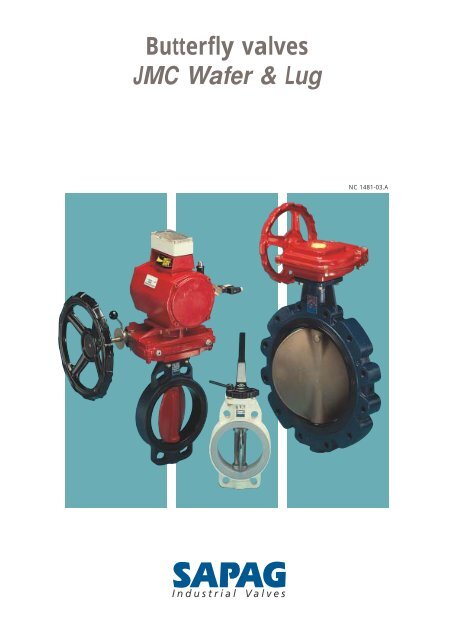
Butterfly valves<br />
<strong>JMC</strong> <strong>Wafer</strong> & <strong>Lug</strong><br />
NC 1481-03.A
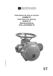
Butterfly valves <strong>JMC</strong> - <strong>Wafer</strong> & <strong>Lug</strong> types<br />
Plate<br />
Standardised to adapt any type of<br />
actuator, conform to ISO 5211 standard.<br />
Chevron Seal<br />
Made in nitrile. This device avoids<br />
atmospheric contamination.<br />
Bearings<br />
Self lubricating bearings made of PTFE<br />
reinforced on a metallic support. These<br />
bearings provide a true shaft guide<br />
and ensure absolute shaft rigidity<br />
during operation.<br />
Shaft<br />
Inside the disc, it is completely insulated<br />
from the liquid being conveyed.<br />
2<br />
FACE TO FACE<br />
dimensions conforming to:<br />
EN 558<br />
API 609 BS 5155<br />
MSS SP 67 DIN 3202-K1<br />
ISO 5752-20 NF E 29305-20<br />
FLANGE STANDARDS<br />
ANSI B 16.5 class 150<br />
BS 4504<br />
BS 10 Table E<br />
ISO 2084<br />
DIN 2501<br />
MSS SP 44<br />
JIS B 2210<br />
NFE 29203<br />
WAFER<br />
LUG
Body<br />
In ductile iron, on standard, providing<br />
higher mechanical properties.<br />
Seat<br />
In removable elastomer, completely<br />
covering the inside of the body. See<br />
details on the opposite side.<br />
Disc<br />
Lenticular in shape, to improve the flow<br />
capacity. It has no internal attachments<br />
or pins to avoid corrosion and internal<br />
leakage. The centered disc allows bidirectional<br />
shut-off.<br />
<strong>Lug</strong>s<br />
For centring and retention. This device<br />
enables the disassembly of the downstream<br />
pipeline, and maintenance of<br />
the valve at the end of the pipe. The full<br />
lug type specially ensures the mounting<br />
at the end of the pipe under maximum<br />
pressure.<br />
Identification<br />
SAPAG<br />
The multi-purpose industrial butterfly valve<br />
SIZE RATING<br />
2“ to 8” (DN 50 - 200) 240 PSI (16 BAR)<br />
10“ to 40“ (DN 250 - 1 000) 150 PSI (10 BAR)<br />
On 2“ to 8” (DN 50 - 200) 300 PSI (20 BAR)<br />
request 10“ to 40” (DN 250 - 1000) 240 PSI (16 BAR)<br />
2“ to 24” (DN 50 - 600) 360 PSI (25 BAR)<br />
3<br />
B<br />
DN 1 000 (40“) FLOVAR<br />
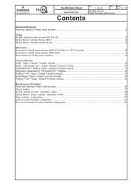
<strong>JMC</strong> butterfly valve. Conventional butterlfy valve.<br />
The thickness provided in the middle of the seat:<br />
• ensures accurate and strictly mechanical anchorage of the seat,<br />
• ensures excellent endurance and better ageing behaviour,<br />
• avoids excessive stresses when the disc is operated<br />
• offers a significant range of angular thightness (± 5°),<br />
• exhibits a constant geometry of the disc/seat tightness.<br />
2<br />
A<br />
At the shaft and spindle, the elastomeric<br />
journals of the seat guarantee tightness:<br />
• on the inside/outside of the valve at<br />
the shaft and spindle,<br />
• upstream/downstream, in the area of<br />
both shaft and spindle.<br />
It should be noted that the shape of the<br />
seal at the shaft and spindle is spherical,<br />
ensuring continous tightness.<br />
A. Concentric grooves on the sides of<br />
the seat to ensure tightness on the<br />
point of all usual flanges.<br />
B. An elastomeric build up, O“ ring<br />
imitation, encased, ensures complementary<br />
tightness.<br />
“<br />
3
Butterfly valves <strong>JMC</strong> - <strong>Wafer</strong> & <strong>Lug</strong> types<br />
Flow characteristics<br />
Flow coefficient K v - Valve opening 90°<br />
4<br />
DN 50 65 80 100 125 150 200 250 300 350 400 450 500 600 700 800 900 1 000<br />
Size 2“ 2“ 1 / 2 3“ 4“ 5“ 6“ 8“ 10“ 12“ 14“ 16“ 18“ 20“ 24“ 28“ 32“ 36“ 40“<br />
K v 110 210 330 610 1 000 1 500 2 700 4 300 6 600 8 900 11 500 15 000 18 800 27 600 38 600 51 500 65 600 81 900<br />
C v 128 245 385 712 1 167 1 750 3 150 5 017 7 700 10 383 13 417 17 500 21 933 32 200 45 033 60 083 76 533 95 550<br />
CV : GPM at 1 PSI differential pressure across valve at standard conditions (60 °F, 14.7 PSIA).<br />
Flow coefficients<br />
The flow coefficient K v is the flow in m 3 /h<br />
of water, at an average temperature of<br />
20 °C, crossing the valve with creating a<br />
headloss of 1 bar.<br />
The relation between Cv and K v is:<br />
C v = 1.16 K v<br />
Characteristics curve<br />
of valve<br />
(K v versus angle<br />
of opening α)<br />
Table of headloss coefficients Kα - Valve opening: 90°<br />
Simplified formula K v : Flow coefficient of the valve<br />
100<br />
90<br />
80<br />
70<br />
60<br />
50<br />
40<br />
30<br />
20<br />
10<br />
0<br />
non<br />
headloss K v compressible gas<br />
fluide<br />
∆p < P1 2<br />
P2 > P1 2<br />
∆p > P1 2<br />
P 2 < P 1<br />
2<br />
% K v or flow<br />
K v<br />
Q<br />
=<br />
31,6<br />
0 10 20 30 40 50 60 70 80 90<br />
Q : Flow in m 3 /h<br />
∆p : Headloss in the valve in bar<br />
P 1 : Upstream pressure in bar<br />
P 2 : Downstream pressure in bar<br />
Q N : Flow in normal conditions<br />
(0 °C, 760 mm Hg) m 3 /h<br />
T : Temperature of the fluid °K<br />
ρ 1 : Volumic weight of the fluid<br />
(kg/m 3 )<br />
ρ N : Volumic weight in normal<br />
conditions<br />
Angle of opening ∝<br />
For liquid, the formula of the headloss with a disc opening angle α is:<br />
ρ Vα 2<br />
∆Pα = ———— Kα ——<br />
10 000 2g<br />
in which:<br />
∆Pα : Headloss in a valve opened to an angle α expressed in bar<br />
Vα : Velocity of the fluid in a pipeline of diameter equal to the one of the valve expressed in m/s when the valve is opened to<br />
an angle α<br />
g : Acceleration of gravity in m/s 2<br />
Kα : Headloss according to the angle to opening. Results in the table<br />
ρ : Volumic weight of the fluid (kg/m 3 )<br />
Vα 2<br />
Nota : In the case of water the formula is simplified : ∆Hα = Kα —— 2g<br />
∆Hα : Headloss on the valve opened to an angle α expressed in meters of water columns.<br />
ρ1 ∆p<br />
QN =<br />
514<br />
2 QN =<br />
514.P1 DN 50 65 80 100 125 150 200 250 300 350 400 450 500 600 700 800 900 1 000<br />
Size 2“ 2“ 1 / 2 3“ 4“ 5“ 6“ 8“ 10“ 12“ 14“ 16“ 18“ 20“ 24“ 28“ 32“ 36“ 40“<br />
Kα 0.82 0.65 0.60 0.43 0.39 0.36 0.35 0.33 0.30 0.30 0.30 0.29 0.28 0.27 0.26 0.25 0.24 0.24<br />
ρ N. T<br />
∆p. P 2<br />
ρ N. T
Pressure<br />
Temperature<br />
Chart<br />
EPDM-S – 15 °C up to + 95 °C*<br />
5 °F up to + 203 °F*<br />
CARBOXYLATED<br />
NITRILE – 15 °C up to + 60 °C<br />
5 °F up to + 140 °F<br />
NITRILE – 15 °C up to + 80 °C<br />
5 °F up to + 176 °F<br />
FLUOROCARBON<br />
ELASTOMER – 15 °C up to + 80 °C<br />
5 °F up to + 176 °F<br />
HYPALON – 15 °C up to + 80 °C<br />
5 °F up to + 176 °F<br />
EPDM – 15 °C up to + 130 °C<br />
5 °F up to + 266 °F<br />
THERBAN – 15 °C up to + 140 °C<br />
5 °F up to + 176 °F<br />
* According to the type of fluid and service<br />
conditions.<br />
Dead<br />
end<br />
Service<br />
Maximum working pressures<br />
VACUUM:<br />
1 Torr<br />
From 50 mm (2“) up to 200 mm (8“)<br />
From 250 mm (10“) up to 400 mm (16“)<br />
From 450 mm (18“) up to 1 000 mm (40“)<br />
NP<br />
(or MWP<br />
at 20 °C)<br />
22<br />
20<br />
16<br />
10<br />
9<br />
5<br />
SEAT<br />
FLUORATED ELASTOMER,<br />
HYPALON,<br />
CARBOXYLED NITRILE<br />
REDUCED TORQUE<br />
(Pneu. act.)<br />
<strong>JMC</strong> - <strong>Wafer</strong> & <strong>Lug</strong> types<br />
Performances<br />
COLD WATER 40 °C<br />
MAXIMUM<br />
CHARACTERISTICS<br />
STANDARD<br />
CHARACTERISTICS<br />
50 100 200 400 600 1000<br />
ND<br />
FACTORY TESTS: Every single valve <strong>JMC</strong> undergoes<br />
hydraulic tests, as per ISO 5208 Standard:<br />
1. For tightness at 1.1. x rating<br />
2. For body strength at 1.5 x rating<br />
Other specific tests on request.<br />
<strong>Lug</strong> <strong>Wafer</strong><br />
BAR BAR<br />
20 BAR (300 PSI)<br />
16 BAR (240 PSI)<br />
10 BAR (150 PSI)<br />
According to PN<br />
10 BAR (150 PSI)<br />
6 BAR ( 90 PSI)<br />
1 BAR ( 15 PSI)<br />
5
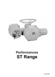
Butterfly valves <strong>JMC</strong> - <strong>Wafer</strong> & <strong>Lug</strong> types<br />
Part list<br />
6<br />
Basic figure<br />
9<br />
6<br />
6<br />
4<br />
8<br />
NOTA : possible neck extension for<br />
insulation.<br />
11<br />
10<br />
7<br />
Rep Nb Designation Material Remarks<br />
1 1 Body (<strong>Wafer</strong> or Full <strong>Lug</strong>) Ductile iron See options<br />
2 1 Disc ASTM A 395-76 grade 60-40-18 See options<br />
3 1 <strong>Control</strong> shaft Stainless steel with 13 % chromium See options<br />
4 1 Spindle Stainless steel with 13 % chromium See options<br />
5 1 Seat EPDM See options<br />
6 3 Self-lubricating Reinforced PTFE<br />
bearings on steel<br />
7 1 Safety nut Steel + polyamid Phosphated<br />
8 1 Protection plug Polyethylene or steel<br />
9 1 Chevron seal Nitrile<br />
10 1 Thru-bolt Galvanized steel<br />
11 1 Key Steel For DN 250 (10“)<br />
12 1 Coupling Stainless steel with 13 % chromium For DN 125 ( 5“)<br />
13 1 Identification plate Aluminium<br />
14 2 Rivet Steel<br />
3<br />
1<br />
5<br />
12<br />
2<br />
11<br />
9<br />
6<br />
3<br />
1<br />
6<br />
5<br />
2<br />
10<br />
4<br />
6<br />
7<br />
8<br />
12<br />
DN 900 mm (36”)<br />
DN 125 mm (5“)<br />
13<br />
14<br />
DN<br />
800 mm<br />
(32")
A<br />
B<br />
DN<br />
Size<br />
Ø L<br />
<strong>JMC</strong> - <strong>Wafer</strong> & <strong>Lug</strong> types<br />
Dimensions<br />
50 74 43 25.5 – 11 – 14 90 – 70 9 4 – – – 110 94 2.8 152<br />
2“ 2.91 1.7 1 – 0.43 – 0.55 3.54 – 2.76 0.35 4.33 3.70 6.17 5.98<br />
65 81 46 25.5 – 11 – 14 90 – 70 9 4 – – – 118 107 3.3 159<br />
2“ 1/2 3.19 1.81 1 – 0.43 – 0.55 3.54 – 2.76 0.35 – – – 4.64 4.21 7.28 6.26<br />
80 93 46 25.5 – 11 – 14 90 – 70 9 4 – – – 125 126 4 166<br />
3“ 3.66 1.81 1 – 0.43 – 0.55 3.54 – 2.76 0.35 – – – 4.92 4.96 8.82 6.54<br />
100 107 52 25.5 – 14 – 16 – 100 102 11 4 – – – 140 150 6 182<br />
4“ 4.21 2.05 1 – 0.55 – 0.63 – 3.94 4.02 0.43 – – – 5.59 5.91 13.23 7.16<br />
125 122 56 25.5 – 14 – 16 – 100 102 11 4 – – – 160 179 8.5 193<br />
5“ 4.80 2.20 1 – 0.55 – 0.63 – 3.94 4.02 0.43 – – – 6.30 7.05 18.74 7.60<br />
150 140 56 25.5 – 19 – 17 – 100 102 11 4 – – – 175 204 11 217<br />
6“ 5.31 2.20 1 – 0.75 – 0.67 – 3.94 4.02 0.43 – – – 6.88 8.03 24.25 8.54<br />
200 167 60 25.5 – 19 – 17 – 100 102 11 4 – – – 206 259 15 242<br />
8“ 6.57 2.36 1 – 0.75 – 0.67 – 3.94 4.02 0.43 – – – 8.11 10.20 33.07 9.53<br />
250 203 68 36 90.5* 27 35 17 – 132 125 14 4 10 8 65 247 313 23 280<br />
10“ 7.87 2.68 1.42 3.56 1.06 1.38 0.67 – 5.20 4.92 0.55 0.39 0.31 2.56 9.72 12.32 50.71 11.02<br />
300 233 78 36 90.5* 27 35 17 – 132 125 14 4 10 8 65 277 369 31 310<br />
12“ 9.17 3.07 1.42 3.56 1.06 1.38 0.67 – 5.20 4.92 0.55 0.39 0.31 2.56 10.89 14.53 68.34 12.20<br />
350 270 78 36 90.5* 27 35 17.5 – 132 125 14 4 10 8 65 300 418 39 350<br />
14“ 10.63 3.07 1.42 3.56 1.06 1.38 0.69 – 5.20 4.92 0.55 0.39 0.31 2.56 11.81 16.46 85.98 13.78<br />
400 300 102 43 90.5* 32 40 21 – 132 140 18 4 12 8 73 345 467 69 375<br />
16“ 11.81 4.02 1.69 3.56 1.26 1.57 0.83 – 5.20 5.51 0.71 0.47 0.31 2.90 13.58 18.39 152.12 14.76<br />
450 330 114 49 100* 36 50 22 – 140 140 18 4 14 9 60 375 521 83 400<br />
18“ 12.99 4.49 1.93 3.93 1.42 1.57 0.87 – 5.51 5.51 0.71 0.55 0.35 2.56 14.76 20.51 182.98 15.75<br />
500 375 127 63 102* 46 60 25 210 – 165 22 4 18 11 80 425 571 107 425<br />
20“ 14.76 5.00 2.48 4.02 1.81 2.36 0.98 8.27 – 6.50 0.87 0.71 0.43 3.15 16.73 22.48 235.89 16.73<br />
600 430 154 63 102* 46 60 25 210 – 165 22 4 18 11 80 495 670 145 495<br />
24“ 16.93 6.06 2.48 4.02 1.81 2.36 0.98 8.27 – 6.50 0.87 0.71 0.43 3.15 19.49 26.38 319.67 19.49<br />
700 510 165 81 110* 55 80 30 300 – 254 18 8 22 14 100 570 776 217 570<br />
28“ 20.08 6.50 3.19 4.33 2.16 3.15 1.18 11.81 – 10.00 0.71 0.87 0.55 3.94 22.44 30.55 478.39 22.44<br />
750 540 165 81 110* 55 80 30 300 – 254 18 8 22 14 100 – – – 610<br />
30“ 21.26 6.50 3.19 4.33 2.16 3.15 1.18 11.81 – 10.00 0.71 0.87 0.55 3.94 – – – 24.02<br />
800 560 190 81 110* 55 80 30 300 – 254 18 8 22 14 100 640 882 310 640<br />
32“ 22.05 7.48 3.19 4.33 2.16 3.15 1.18 11.81 – 10.00 0.71 0.87 0.55 3.94 25.19 34.72 683.57 25.19<br />
900 665 203 – 110 – 100 30 300 – 254 18 8 28 16 100 700 1 000 448 700<br />
36“ 26.18 7.99 – 4.33 – 3.94 1.18 11.81 – 10.00 0.71 1.10 0.63 3.94 27.56 39.37 987.87 27.56<br />
1 000 715 216 – 110 – 100 30 350 – 298 22 8 28 16 100 750 1 105 530 750<br />
40“ 28.15 8.50 – 4.33 – 3.94 1.18 13.78 – 11.73 0.87 1.10 0.63 3.94 29.53 43.50 1168.69 29.53<br />
DN 1000 (40") : FLOVAR<br />
<strong>Wafer</strong> type Full <strong>Lug</strong> type<br />
H<br />
E1<br />
N Holes Ø M<br />
B C E 1 E 2 F ∅ G<br />
Ø J or K<br />
C<br />
F<br />
Ø D<br />
A<br />
B<br />
Ø J or K<br />
F<br />
H<br />
Ø D<br />
N Holes Ø M<br />
Ø L<br />
P<br />
C<br />
E 1<br />
I<br />
Ø J or K<br />
Ø G<br />
Key a x b x l<br />
Actuator flange Key <strong>Wafer</strong> type Full <strong>Lug</strong> type<br />
H ∅ J K ∅ L M N a b I A ∅ D Weights A<br />
a<br />
b<br />
E2<br />
∅ D P Weights<br />
153 38 3.7<br />
6.02 1.50 8.16<br />
173 40 4.2<br />
6.81 1.57 9.26<br />
188 40 7.1<br />
7.39 1.57 15.65<br />
219 45 8.7<br />
8.61 1.77 19.18<br />
252 48 11<br />
9.92 1.89 24.25<br />
278 48 15<br />
10.93 1.89 33.06<br />
335 52 22<br />
13.17 2.05 45.50<br />
400 60 33<br />
15.73 2.36 72.75<br />
470 70 44<br />
18.48 2.76 97.00<br />
520 70 67<br />
20.45 2.76 147.50<br />
588 90 104<br />
23.12 3.54 229.28<br />
633 100 136<br />
24.89 3.94 299.83<br />
704 113 180<br />
27.68 4.45 396.84<br />
828 140 260<br />
32.56 5.51 573.20<br />
895 150 280<br />
35.24 5.91 617.29<br />
972 150 400<br />
38.27 5.91 881.85<br />
1 010 170 400<br />
39.75 6.69 881.85<br />
1 152 190 543<br />
45.35 7.48 1355.83<br />
1 240 190 660<br />
49.02 7.48 1455.04<br />
* On request. Dimensions in mm, weights in kg.<br />
Dimensions and weights are given as a guide.<br />
7
Butterfly valve <strong>JMC</strong> - <strong>Wafer</strong> & <strong>Lug</strong> <strong>Types</strong><br />
Description<br />
8<br />
Body<br />
Disc<br />
Shaft and spindle<br />
Seat<br />
External body<br />
coating<br />
Standard<br />
Cast ductile iron:<br />
ASTM A 395 Gr 60.40.18<br />
Cast ductile iron:<br />
ASTM A 395 Gr 60.40.18<br />
epoxy or Rilsan coated<br />
nickel plated<br />
Cupro-aluminium:<br />
Cu Al 9 Ni3 Fe2 DN ≤ 200 (8“)<br />
Cu Al 10 Ni5 Fe5 DN ≥ 250 (10“)<br />
Z3 CND 17-11-02 DN ≤ 200 (8“)<br />
Z6 CND 18-12 M DN > 200 (8“)<br />
Polished on request<br />
Stainless steel: AISI 420<br />
EPDM-S (– 15 + 95 °C*)<br />
EPDM (– 15 + 130 °C)<br />
Nitrile NBR (– 15 + 80 °C)<br />
Nitrile X-NBR (– 15 + 60 °C)<br />
Epoxy + paint<br />
® Registered trade mark.<br />
ASTM Grades are approximate and given as an indication<br />
* According to the type of fluid and service conditions.<br />
Other executions<br />
Carbon steel: ASTM A 216 WCB<br />
Stainless steel: ASTM A351-CF3M<br />
• Cast ductile iron 60.40.18<br />
• EPDM or NBR rubber coated<br />
DN ≤ 300 (12“)<br />
• Natural rubber coated<br />
DN > 300 (12“)<br />
• Halar ® coated<br />
Monel 400 ®<br />
Uranus B6 ®<br />
Other types on request<br />
Stainless steel: AISI 17.4 PH<br />
Monel<br />
Cupro-aluminium<br />
EPDM white (– 15 + 130 °C)<br />
Fluorated elastomer (– 15 + 130 °C)<br />
Hypalon CSM ® (– 15 + 80 °C)<br />
Therban (– 15 + 140 °C)<br />
Any other<br />
Epoxy coating<br />
on request
<strong>JMC</strong> - <strong>Wafer</strong> & <strong>Lug</strong> <strong>Types</strong><br />
Applications Approvals<br />
General utilities<br />
Water treatment<br />
Cements plants<br />
Mechanical engineering<br />
Mining industries<br />
Steel and aluminium plants<br />
Food industries<br />
Sugar refineries<br />
Shipbuilding and offshore<br />
TYPICAL FLUIDS<br />
Cold water<br />
Hot water<br />
Demineralized water<br />
Sea water<br />
Air - Heating - HVAC<br />
Bulkhandling (pneumatic transport)<br />
Foodstuff<br />
Sulfuric and chlorydric acids<br />
Mineral oil<br />
Petroleum products<br />
Sugar process<br />
Possible<br />
THERBAN<br />
Pulp and paper mills<br />
Automotive industries<br />
Chemical - Petrochemical<br />
Power generation<br />
Heating, Ventilating<br />
and Air conditionning<br />
Gas process<br />
Fire protection systems<br />
Agriculture - Irrigation<br />
Bulk handling<br />
fluids<br />
EPDM-S<br />
• DCAN<br />
Endurance against stresses<br />
• VERITAS<br />
• Mechanical Engineering Laboratories<br />
Hong Kong<br />
• KTW<br />
• SNCF<br />
• ADR<br />
• LLOYD’S REGISTER OF SHIPPING<br />
• EDF<br />
• DVGW<br />
Deutscher Verein des Gas- und<br />
Wasser- fachers e.v.<br />
• CEMATH<br />
• Town of Paris<br />
• UL<br />
Underwritters Laboratory, Chicago<br />
• VDS<br />
• OFFICE OF WATER AUTHORITY<br />
(Hong Kong)<br />
• FIRE SERVICE (Hong Kong)<br />
• DET NORSKE VERITAS<br />
• WRC Water Research Council<br />
• Certificats of foodstuff quality on<br />
request (Poitiers laboratory - France)<br />
SUITABLE SEAT SUITABLE DISC<br />
EPDM<br />
Nitrile<br />
Carboxyled Nitrile X-NBR<br />
Hypalon ®<br />
Fluorated elastomer<br />
Iron + Epoxy<br />
Nickel<br />
Naturel rubber<br />
Halar ®<br />
Cupro-aluminium<br />
Stainless steel<br />
Monel 400 ®<br />
Uranus B6 ®<br />
® Registered trade mark<br />
9
Butterfly valves <strong>JMC</strong> - <strong>Types</strong> <strong>Wafer</strong> & <strong>Lug</strong> <strong>Types</strong><br />
Synoptic table of the different actuators<br />
10<br />
ISO 5211<br />
mounting<br />
flange<br />
Bare shaft<br />
<strong>JMC</strong> valve<br />
WAFER<br />
Bare shaft<br />
<strong>JMC</strong> valve<br />
FULL LUG<br />
MANUAL ACTUATOR<br />
HOLD POSITION GEAR<br />
MULTITURN 1/4 TURN<br />
ELECTRIC PNEUMATIC<br />
ACTUATORS ACTUATORS<br />
Lockable lever LF<br />
DN 50-250 / 2“-10“<br />
Notched lever LC<br />
DN 50-150 / 2“-6“<br />
Worm gear MG<br />
DN 50-1 000 / 2“-40“<br />
Worm gear MF<br />
DN 50-400 / 2“-16“<br />
FE - DN 50-125 / 2“-5”<br />
FA - DN 50-125 / 2”-5”<br />
Double acting actuator SIROCCO<br />
DN 50-1 000 / 2“-40“<br />
SIngle acting actuator SIROCCO<br />
DN 50-450 / 2“-18“<br />
Actuators BERNARD<br />
DN 50-1 000 / 2“-40“<br />
LF<br />
LC<br />
MG<br />
MF<br />
FE<br />
FA<br />
D<br />
S
Lockable lever LF<br />
C<br />
G<br />
Ø D<br />
E<br />
A<br />
B<br />
Notched lever LC<br />
C<br />
H<br />
G<br />
Ø D<br />
E<br />
B A<br />
F<br />
F<br />
<strong>JMC</strong> - <strong>Wafer</strong> & <strong>Lug</strong> <strong>Types</strong><br />
Manual actuators<br />
Size DN Type A B C ∅ D E F G<br />
Weights<br />
<strong>Wafer</strong> <strong>Lug</strong><br />
2“ 50 LF4 110 74 43 94 230 69 45 3.8 4.7<br />
2“ 1 / 2 65 LF4 118 81 46 107 230 69 45 4.3 5.2<br />
3“ 80 LF4 125 93 46 126 230 69 45 5 8.1<br />
4“ 100 LF12 140 107 52 150 320 75 63 7.6 10.3<br />
5“ 125 LF12 160 122 56 179 320 75 63 10.1 12.7<br />
6“ 150 LF20 175 135 56 204 420 75 63 13.1 17.1<br />
8“ 200 LF20 206 167 60 259 420 75 63 17.1 24.1<br />
10“ 250 LF50 247 200 68 313 702 150 82 30.6 40.6<br />
Dimensions in mm, weights in kg - Dimensions and weights are given as a guide.<br />
Throttling<br />
Size DN Type A B C ∅ D E F G H<br />
2“ 50 LC4 110 74 43 94 230 71 15 45 3.3 4.2<br />
2“ 1 / 2 65 LC4 118 81 46 107 230 71 15 45 3.8 4.7<br />
3“ 80 LC4 125 93 46 126 230 71 15 45 4.5 7.6<br />
4“ 100 LC12 140 107 52 150 320 77 15 50 6.7 9.4<br />
5“ 125 LC12 160 122 56 179 320 77 15 50 9.3 11.8<br />
6“ 150 LC20 175 135 56 204 420 77 25 50 12 16<br />
Dimensions in mm, weights in kg - Dimensions and weights are given as a guide.<br />
Number of locking positions<br />
LC4 = 9, LC12 = 9, LC20 = 7<br />
Weights<br />
<strong>Wafer</strong> <strong>Lug</strong><br />
11
Butterfly valves <strong>JMC</strong> - <strong>Wafer</strong> & <strong>Lug</strong> <strong>Types</strong><br />
Manual actuators<br />
Hold position gear FA<br />
Hold position gear FE<br />
Ø D<br />
C<br />
Worm gear MF<br />
H<br />
A<br />
B<br />
C<br />
Worm gear MG<br />
A'<br />
B'<br />
12<br />
M<br />
G<br />
Ø D<br />
E<br />
A<br />
B<br />
K<br />
J<br />
E'<br />
F<br />
Ø J<br />
A B<br />
∅ D<br />
∅ V<br />
C<br />
Ø D<br />
E<br />
Ø V<br />
C<br />
H<br />
∅ D<br />
F<br />
F<br />
G<br />
K<br />
K<br />
J<br />
F<br />
A<br />
B<br />
G<br />
E<br />
Size DN Actuator A B C ∅ D G<br />
2“ 50<br />
110 74 43 94 100 230 113 16 86.5 9 4.7 5.6 4.5 5.4<br />
FA 11<br />
2“ 1 / 2 65<br />
118 81 46 107 100 230 113 16 86.5 9 5.2 6.1 5 5.9<br />
FE 11<br />
3“ 80 125 93 46 126 100 230 113 16 86.5 9 5.9 9 5.7 8.8<br />
4“ 100 FA 14 140 107 52 150 100 310 128 16 86.5 9 10 12.7 9.5 12.2<br />
5“ 125 FE 14 160 122 56 179 100 310 128 16 86.5 9 12.4 14.9 12 14.5<br />
Hold position gear FA closed: FSH<br />
Hold position gear FE closed:<br />
FAH or FSH to precise<br />
Number of locking position:<br />
MF 1 : 10 MF 2 : 17<br />
FA FE Weights<br />
E F ∅ J F K<br />
Dimensions in mm, weights in kg - Dimensions and weights are given as a guide.<br />
Dimensions in mm, weights in kg - Dimensions and weights are given as a guide.<br />
Dimensions in mm, weights in kg - Dimensions and weights are given as a guide.<br />
FA FE FA FE<br />
<strong>Wafer</strong> <strong>Lug</strong><br />
Weights<br />
Size DN Actuator A B C ∅ D E H J K ∅ V M<br />
<strong>Wafer</strong> <strong>Lug</strong><br />
2“<br />
2“<br />
50 110 74 43 94 130 88 75 186 125 28 9.8 10.7<br />
1 / 2<br />
3“<br />
65<br />
80<br />
118<br />
125<br />
81<br />
93<br />
46<br />
46<br />
107<br />
126<br />
138<br />
155<br />
88<br />
88<br />
75<br />
75<br />
186<br />
186<br />
125<br />
125<br />
28<br />
28<br />
10.3<br />
11<br />
11.2<br />
14.1<br />
4“ 100 MF 1 140 107 52 150 170 88 75 186 125 28 13 15.7<br />
5“ 125 160 122 56 179 190 88 75 186 125 28 15.5 18<br />
6“ 150 175 135 56 204 205 88 75 193 225 28 18 22<br />
8“ 200 206 170 60 259 236 88 75 193 225 28 22 29<br />
10“ 250 247 200 68 313 298 129 132 276 300 27 43 53<br />
12“<br />
14“<br />
300<br />
350 MF 2<br />
277<br />
300<br />
233<br />
270<br />
78<br />
78<br />
369<br />
418<br />
328<br />
351<br />
129<br />
129<br />
132<br />
132<br />
276<br />
276<br />
300<br />
300<br />
27<br />
27<br />
51<br />
59<br />
64<br />
87<br />
16“ 400 345 300 102 467 396 129 132 276 300 27 89 124<br />
Size DN Type A A’ B B’ C ∅ D ∅ D’ E E’ F G H J K ∅ V Weights<br />
<strong>Wafer</strong> <strong>Lug</strong><br />
2“ 50 MG 50 110 152 74 76 43 94 153 145 187 58 84 67 52 145 150 7,8 8,7<br />
2“ 1 / 2 65 MG 50 118 159 81 84 46 107 173 153 194 58 84 67 52 145 150 8,3 9,2<br />
3“ 80 MG 50 125 166 93 90 46 126 188 160 201 58 84 67 52 145 150 9 12,1<br />
4“ 100 MG 50 140 182 107 109 52 150 219 175 217 58 84 67 52 145 150 11 13,7<br />
5“ 125 MG 50 160 193 122 120 56 179 252 195 228 58 84 67 52 145 150 13,5 16<br />
6“ 150 MG 50 175 217 135 140 56 204 278 210 252 58 84 67 52 145 150 16 20<br />
8“ 200 MG 50 206 242 170 167 60 259 335 241 277 58 84 67 52 145 150 20 27<br />
10“ 250 MG 100 247 280 200 203 68 313 400 289 322 75 105 81 67 176 255 32 40<br />
12“ 300 MG 100 277 310 233 228 78 369 470 319 352 75 105 81 67 176 255 40 53<br />
14“ 350 MG 100 300 350 270 270 78 418 520 342 392 75 105 81 67 223 356 49 77<br />
16“ 400 MG 180 345 375 300 300 102 467 588 395 425 99 131 94 90 315 356 85,5 120,5<br />
18“ 450 MG 180 375 400 330 330 114 521 633 425 450 99 131 94 90 315 356 99,5 152,5<br />
20“ 500 MG 180 425 425 375 375 127 571 704 475 475 99 131 94 90 358 457 123,5 196,5<br />
24“ 600 MG 340 495 495 430 430 154 670 828 545 545 126 178 106 123 335 457 176 291<br />
28“ 700 MG 450 570 570 510 510 165 776 895 620 620 158 209 127 154 362 457 262 325<br />
DN > 700 : nous consulter
Double acting pneumatic actuator SIROCCO-D type<br />
Air supply pressure: 5 bar (75 PSI) (Other pressure: on request)<br />
Single acting pneumatic actuator SIROCCO-S type<br />
Air supply pressure: 5 bar (75 PSI) (Other pressure: on request)<br />
Ø D<br />
J<br />
C<br />
L<br />
<strong>JMC</strong> - <strong>Wafer</strong> & <strong>Lug</strong> <strong>Types</strong><br />
Pneumatic actuators<br />
Dimensions in mm, weights in kg. Dimensions and weights are given as a guide.<br />
* Fail to close. Dimensions in mm, weights in kg. Dimensions and weights are given as a guide.<br />
F<br />
K<br />
H<br />
A<br />
B<br />
C<br />
<strong>Wafer</strong> <strong>Lug</strong><br />
Size DN D Type<br />
A<br />
<strong>Wafer</strong> <strong>Lug</strong><br />
B<br />
<strong>Wafer</strong> <strong>Lug</strong><br />
C<br />
D<br />
<strong>Wafer</strong> <strong>Lug</strong><br />
F H J K<br />
L<br />
<strong>Wafer</strong> <strong>Lug</strong><br />
Weights<br />
<strong>Wafer</strong> <strong>Lug</strong><br />
2“ 50 30 110 152 74 76 43 94 153 77 87 122 47 217 259 4.1 5.1<br />
2“ 1 / 2 65 30 118 159 81 84 46 107 173 77 87 122 47 225 266 4.6 5.6<br />
3“ 80 60 125 166 93 90 46 126 188 95 102 165 54 247 288 6.2 9.3<br />
4“ 100 140 140 182 107 109 52 150 219 127 133 174 72 293 335 9.5 12.2<br />
5“ 125 140 160 193 122 120 56 179 252 127 133 174 72 313 346 12 14.5<br />
6“ 150 270 175 217 135 140 56 204 278 152 160 212 89 355 397 17.5 21.5<br />
8“ 200 500 206 242 170 167 60 259 335 192 189 270 109 425 461 28 35<br />
10“ 250 500 247 280 200 203 68 313 400 192 189 270 109 466 499 36 46<br />
12“ 300 750 277 310 233 228 78 369 470 240 232 282 134 539 572 51 71<br />
14“ 350 1 100 300 350 270 270 78 418 520 250 245 340 135 575 625 66 94<br />
16“ 400 2 500 345 375 300 300 102 467 588 350 356 378 185 731 861 130 165<br />
18“ 450 2 500 375 400 330 330 114 521 633 350 356 378 185 861 886 144 197<br />
20“ 500 2 500 425 425 375 375 127 571 704 350 356 378 185 811 811 164 237<br />
24“ 600 4 000 495 495 430 430 154 670 828 380 380 502 200 905 905 232 347<br />
28“ 700 4 000 570 570 510 510 165 776 895 380 380 502 200 980 980 304 367<br />
DN > 700 : on request<br />
Size DN S Type<br />
A<br />
<strong>Wafer</strong> <strong>Lug</strong><br />
B<br />
<strong>Wafer</strong> <strong>Lug</strong><br />
C<br />
D<br />
<strong>Wafer</strong> <strong>Lug</strong><br />
F H J<br />
K<br />
<strong>Wafer</strong> <strong>Lug</strong><br />
L<br />
<strong>Wafer</strong> <strong>Lug</strong><br />
Weights<br />
<strong>Wafer</strong> <strong>Lug</strong><br />
2“ 50 60 110 152 74 76 43 94 153 95 102 165 54 54 232 274 5.5 6.4<br />
2“ 1 / 2 65 140 118 159 81 84 46 107 173 127 133 209 72 72 271 312 8.3 9.2<br />
3“ 80 140 125 166 93 90 46 126 188 127 133 209 72 72 278 319 9 12.1<br />
4“ 100 270 140 182 107 109 52 150 219 152 160 291 89 89 320 362 15.5 18.2<br />
5“<br />
125 270<br />
500*<br />
160<br />
160<br />
193<br />
193<br />
122<br />
122<br />
120<br />
120<br />
56<br />
56<br />
179<br />
179<br />
252<br />
252<br />
152<br />
192<br />
160<br />
189<br />
291<br />
352<br />
89<br />
109<br />
89<br />
109<br />
340<br />
379<br />
373<br />
412<br />
18<br />
27<br />
20.5<br />
29<br />
6“<br />
150 500<br />
750*<br />
175<br />
175<br />
217<br />
217<br />
135<br />
135<br />
140<br />
140<br />
56<br />
56<br />
204<br />
204<br />
278<br />
278<br />
192<br />
240<br />
189<br />
232<br />
352<br />
380<br />
109<br />
134<br />
109<br />
134<br />
394<br />
437<br />
436<br />
479<br />
29<br />
41<br />
33<br />
45<br />
8“ 200 1 100 206 242 170 167 60 259 335 250 245 475 135 135 481 517 53 60<br />
10“ 250 2 500 247 280 200 203 68 313 400 350 356 570 185 185 633 666 112 116<br />
12“ 300 2 500 277 310 233 228 78 369 470 350 356 570 185 185 663 696 120 133<br />
14“<br />
350 2 500<br />
4 000*<br />
300<br />
300<br />
350<br />
350<br />
270<br />
270<br />
270<br />
270<br />
78<br />
78<br />
418<br />
418<br />
520<br />
520<br />
350<br />
380<br />
356<br />
380<br />
570<br />
834<br />
185<br />
200<br />
185<br />
203<br />
686<br />
710<br />
736<br />
760<br />
128<br />
171<br />
156<br />
199<br />
16“ 400 4 000 345 375 300 300 102 467 588 380 380 834 200 203 755 805 225 240<br />
18“ 450 4 000 375 400 330 330 114 521 633 380 380 834 200 203 785 830 239 272<br />
DN > 450 : on request<br />
J<br />
L<br />
Ø D<br />
F<br />
K<br />
H<br />
A<br />
B<br />
13
Butterfly valves <strong>JMC</strong> - <strong>Wafer</strong> et <strong>Lug</strong> <strong>Types</strong><br />
Pneumatic actuators: Accessories and options<br />
14<br />
Double or single acting pneumatic<br />
SIROCCO actuator<br />
<strong>Wafer</strong><br />
<strong>Lug</strong><br />
EXTERNAL LIMIT<br />
SWITCHES<br />
• Protection to IP 67<br />
• Working temperature:<br />
– 25 °C to + 70 °C<br />
• 300 volts - 6 A<br />
On request:<br />
• Explosion proof switches E Ex “d”<br />
• Stirrup inox<br />
Key lever for double or single acting<br />
pneumatic actuators<br />
Distributor for pneumatic actuators.<br />
ISOBOX<br />
• Protection to IP 67<br />
• Working temperatures:<br />
– 25 °C to + 100 °C<br />
LIMIT SWITCHES<br />
IN BOX<br />
• Box in alloyed aluminium<br />
or polycarbonate<br />
• Protection to IP 65<br />
• Working temperature:<br />
– 25 °C to + 80 °C<br />
• 2 A - 24 VDC<br />
16 A - 250 VAC<br />
• Adjustable cams from 0° to 90°<br />
Manual acting “CM” type<br />
for double or single acting<br />
pneumatic actuators<br />
• 4 possibilities:<br />
– 2 A - 24 VDC<br />
16 A - 250 VAC<br />
– proximity AC supply<br />
– proximity DC supply
PROXIMITY DETECTORS<br />
IN BOX<br />
• Box in alloyed aluminium<br />
or polycarbonate<br />
• Protection to IP 65<br />
• Working temperature:<br />
– 25 °C to + 80 °C<br />
• Electricity supply<br />
all voltages, AC or DC supply<br />
On request:<br />
• Explosion proof switches E Ex “i”<br />
• Type : monostable or bistable<br />
• Electric supply: voltage, DC or AC supply, on request<br />
• Working temperature : – 10 °C à + 60 °C<br />
• Equiped with noise orspeed reducer manual operating<br />
• On request pneumatic operating<br />
Size of valve TYPE<br />
50 to 200<br />
2“ to 8“<br />
250 to 600<br />
10“ to 24<br />
ISOBOX 1<br />
ISOBOX 2<br />
<strong>JMC</strong> - <strong>Wafer</strong> & <strong>Lug</strong> <strong>Types</strong><br />
D 25 30 60 140 270 500 750 1 100 2 500 4 000<br />
Double acting Key CD1 CD1 CD1 CD2 CD2 – – – – –<br />
CM – – – CM1* CM1* CM2 CM2 CM2 CM3 CM3<br />
SNH 25 30 60 140 270 500 750 1 100 2 500 4 000<br />
Simple acting Key CS1 CS1 CS1 – – – – – – –<br />
* On request.<br />
PNEUMATIC<br />
POSITIONERS (standard)<br />
• Protection to IP 54<br />
• Working temperature:<br />
– 15 °C to + 80 °C (– 40 °C on request)<br />
• Air supply pressure:<br />
1.4 to 6 bar (20 to 50 Psi)<br />
• Signal: 0.2 to 1 bar (3 to 50 Psi)<br />
ELECTROPNEUMATIC POSITIONERS (standard)<br />
• Protection to IP 54<br />
• Working temperature: – 15 °C to + 80 °C<br />
• Input signal: 4-20 mA<br />
CM – – – CM1 CM1 CM2 CM2 CM2 CM3 CM3<br />
15
Butterfly valves <strong>JMC</strong> - <strong>Wafer</strong> et <strong>Lug</strong> <strong>Types</strong><br />
Electric actuators BERNARD type<br />
Technical data<br />
– Electrical supply:<br />
230/400 V 3 phase, 50 Hz;<br />
Other on request.<br />
– Connection:<br />
every single actuator is delivered with a<br />
wiring notice.<br />
– Protection: IP 67 (Z3: IP65).<br />
– Explosion proof version on request.<br />
Ø V<br />
P<br />
Ø V<br />
H<br />
16<br />
Ø D<br />
M N<br />
M N<br />
E<br />
H<br />
A<br />
B<br />
P<br />
E<br />
A<br />
B<br />
C<br />
2 x Pg 16<br />
(STANDARD)<br />
Dimensions in mm, weights in kg - Dimensions and weights are given as a guide.<br />
P<br />
H<br />
Ø V<br />
Ø D<br />
M N<br />
RS + SRA 6 Type RS + SR 12 Type<br />
Dimensions in mm, weights in kg<br />
Dimensions and weights are given as a guide.<br />
86<br />
20<br />
Ø D<br />
163<br />
73 90<br />
C<br />
A<br />
B<br />
C<br />
E<br />
Ø V<br />
Ø D<br />
Type of actuator 1/4 turn Multiturn<br />
Z3 OA AS/BS SR<br />
Travel stops X X X on RS<br />
Limit switch for open and close position X X X X<br />
Torque switches (adjustable according to the sense of rotation) X X<br />
Handwheel for manual action X X X X<br />
1/4 turn actuator Multiturn actuator<br />
M<br />
N<br />
A<br />
B<br />
E<br />
Z3 Type OA Type AS-BS Type<br />
Size DN<br />
A<br />
<strong>Wafer</strong> <strong>Lug</strong><br />
B C<br />
∅ D<br />
<strong>Wafer</strong> <strong>Lug</strong><br />
E<br />
<strong>Wafer</strong> <strong>Lug</strong><br />
M N P ∅ V<br />
Weights<br />
<strong>Wafer</strong> <strong>Lug</strong><br />
2“<br />
2“<br />
50 Z 3 11 110 152 74 43 94 153 158 200 134 59 344 60 7,8 8,7<br />
1 / 2 65 Z 3 11 118 159 81 46 107 173 166 207 134 59 352 60 8,3 9,2<br />
2“<br />
2“<br />
50 OA 6 6 110 152 74 43 94 153 179 221 90 200 325 60 8,5 9,7<br />
1 Type of<br />
actuator<br />
Operating<br />
time<br />
/ 2<br />
3“<br />
65<br />
80<br />
OA 6<br />
OA 6<br />
6<br />
6<br />
118<br />
125<br />
159<br />
166<br />
81<br />
93<br />
46<br />
46<br />
107<br />
126<br />
173<br />
188<br />
187<br />
194<br />
228<br />
235<br />
90<br />
90<br />
200<br />
200<br />
333<br />
340<br />
60<br />
60<br />
9<br />
9,7<br />
10,2<br />
13,1<br />
4“ 100 OA 8 6 140 182 107 52 150 219 219 251 90 200 365 60 13 16<br />
5“ 125 OA 15 15 160 193 122 56 179 252 239 262 112 260 385 100 16 18,5<br />
4“ 100 AS 18 5 140 182 107 52 150 219 240 282 187 312 317 100 22 25<br />
5“ 125 AS 18 5 160 193 122 56 179 252 260 293 187 312 357 100 24,5 27<br />
6“ 150 AS 18 5 175 217 135 56 204 278 275 317 187 312 352 100 27 31<br />
8“ 200 AS 32 43 206 242 167 60 259 335 306 342 187 340 383 165 32 39<br />
10“ 250 AS 80 60 247 280 200 68 313 400 377 380 187 340 454 250 43 53<br />
12“ 300 AS 80 60 277 310 233 78 369 470 407 410 187 340 484 250 51 64<br />
14“ 350 BS 100 60 300 350 270 78 418 520 386 418 187 393 467 250 65 97<br />
16“ 400 BS 150 60 345 375 300 102 467 558 431 461 187 393 512 250 97 132<br />
C<br />
P<br />
Size DN<br />
Type of<br />
actuator<br />
Operating<br />
time<br />
A<br />
<strong>Wafer</strong> <strong>Lug</strong><br />
B C<br />
∅ D<br />
<strong>Wafer</strong> <strong>Lug</strong><br />
E<br />
<strong>Wafer</strong> <strong>Lug</strong><br />
M N P ∅ V<br />
Weights<br />
<strong>Wafer</strong> <strong>Lug</strong><br />
4“ 100 RS 50 + SRA 6 18 140 182 107 52 150 219 188 230 404 87 249 300 40 46<br />
5“ 125 RS 50 + SRA 6 18 160 193 122 56 179 252 209 241 404 87 269 300 42,5 48<br />
6“ 150 RS 50 + SRA 6 18 175 217 135 56 204 278 223 265 404 87 284 300 45 52<br />
8“ 200 RS 50 + SRA 6 18 206 242 170 60 259 335 254 290 404 87 315 300 49 59<br />
10“ 250 RS 100 + SRA 6 24 247 280 200 68 313 400 306 333 426 125 374 300 62 75<br />
12“ 300 RS 100 + SRA 6 24 277 310 233 78 369 470 336 363 426 125 404 300 70 86<br />
14“ 350 RS 100 + SRA 6 24 300 350 270 78 418 520 359 403 426 125 427 300 78 109<br />
16“ 400 RS 250 + SRA 6 51 345 375 300 102 467 588 410 460 491 189 488 300 140 177<br />
18“ 450 RS 250 + SRA 6 51 375 400 330 114 521 633 440 485 491 189 518 300 158 209<br />
20“ 500 RS 250 + SRA 6 69 425 425 375 127 571 704 490 513 580 189 568 300 182 253<br />
24“ 600 RS 600 + SRA 6 69 495 495 430 154 670 828 583 583 580 212 687 300 215 333<br />
28“ 700 RS 1825 G + SRA 6 135 570 570 510 165 776 895 687 687 786 252 812 300 337 412<br />
32“ 800 RS 1825 G + SRA 6 135 640 640 560 190 882 1 010 757 757 786 252 882 300 430 532<br />
36“ 900 RS 1825 G + SR 12 138 700 700 665 203 1 000 1 148 817 852 771 252 942 300 595 697<br />
40“ 1 000 RS 1830 G + SR 12<br />
DN > 1 000 : nous consulter<br />
138 750 750 715 216 1 105 1 240 902 902 771 252 1 027 300 687 807<br />
Ø V<br />
Ø D<br />
M<br />
N<br />
A<br />
B<br />
E<br />
C<br />
P
Assembly on line<br />
Between flanges assembly for wafer type<br />
1. Leave sufficient space between the<br />
flanges to avoid injury to the sides of the<br />
seat while sliding the valve between the<br />
two flanges. Be sure that these edges<br />
have well aligned, parallel, and erect<br />
sealing faces.<br />
2. Center the valve by bolting the body<br />
locator first.<br />
<strong>JMC</strong> - <strong>Wafer</strong> & <strong>Lug</strong> <strong>Types</strong><br />
Mounting<br />
3. Progressively tighten diametrically<br />
opposed bolts by alternating sides until<br />
contact has been made between the<br />
metal valve body and the flange faces.<br />
Tighten bolts fully.<br />
4. <strong>Control</strong> after mounting: operate the<br />
valve from fully open position to fully<br />
closed position to make sure that<br />
nothing is obstructing the disc.<br />
Size 2“ 2“1/2 3“ 4“ 5“ 6“ 8“ 10“ 12“ 14“ 16“ 18“ 20“ 24“ 28“ 32“ 36“ 40“<br />
DN 50 65 80 100 125 150 200 250 300 350 400 450 500 600 700 800 900 1 000<br />
DIN 2501 PN 6 1 1 1 1-2 1 1-3<br />
BS 4504 PN 10 1-2 1-2 1 1-3 1-3 1-3 1-3<br />
ISO 2084 PN 16 1 1-2 1-2 1 1-3 1-3 1-3 1-3<br />
PN 20/ANSI B 16.5 Class 150 1 1-2 1<br />
BS 10 Table E 1 1 1 1<br />
JIS B 2210<br />
JIS 10 K<br />
JIS 16 K 1 1<br />
1<br />
1<br />
1<br />
1<br />
1<br />
1 1<br />
1<br />
1 1<br />
1<br />
1<br />
1<br />
1 1<br />
1-2<br />
1<br />
1-2<br />
1<br />
1<br />
1<br />
1-3<br />
1-3<br />
1-3<br />
1-3<br />
1-3<br />
1-3<br />
1-3<br />
1-3<br />
MSS SP 44 Class 150 1 1-2 1 1-3 1-3 1-3 1-3<br />
Possible 1 To be specified in the order 2 4 tapped holes 3 4 tapped holes blind<br />
Dead end assembly for wafer type<br />
DN 50 60 80 100 125 150 200 250 300 350 400 450 500 600 700 800 900 1 000<br />
DIN 2501 PN 6 1-2 1-3<br />
BS 4504 PN 10<br />
ISO 2084 PN 16<br />
PN 20/ANSI B 16.5 Class 150<br />
BS 10 Table E 1-3<br />
JIS 10 K<br />
JIS B 2210<br />
JIS 16 K<br />
MSS SP 44 Class 150<br />
Possible<br />
Size 2“ 2“1/2 3“ 4“ 5“ 6“ 8“ 10“ 12“ 14“ 16“ 18“ 20“ 24“ 28“ 32“ 36“ 40“<br />
Pressure : See page 5<br />
Between flanges and dead end assembly for full lug<br />
Size 2“ 2“1/2 3“ 4“ 5“ 6“ 8“ 10“ 12“ 14“ 16“ 18“ 20“ 24“ 28“ 32“ 36“ 40“<br />
DN 50 65 80 100 125 150 200 250 300 350 400 450 500 600 700 800 900 1 000<br />
DIN 2501 PN 6<br />
BS 4504 PN 10 1<br />
ISO 2084 PN 16 1<br />
PN 20/ANSI B 16.5 Class 150<br />
BS 10 Table E<br />
JIS 10 K<br />
JIS B 2210<br />
JIS 16 K<br />
MSS SP 44 Class 150<br />
Pressure: See page 5<br />
Possible 1 On request<br />
1<br />
1<br />
17
Butterfly valves <strong>JMC</strong> - <strong>Wafer</strong> & <strong>Lug</strong> <strong>Types</strong><br />
Maintenance and marking of the seat<br />
1. Removal<br />
of the seat<br />
Maintenance procedure:<br />
1. Remove the valve actuator.<br />
2. Pull out the protection plug .<br />
3. Remove the “V” Ring seal .<br />
4. Unscrewed and remove the safety<br />
nut .<br />
5. Extract the control shaft and its thrubolt<br />
after having placed the disc <br />
in open position and located the orientation<br />
of the key (for sizes 10“ to 40“<br />
- 250 mm to 1 000 mm).<br />
6. Remove the spindle .<br />
7. Remove the disc .<br />
8. Displace the seat from the center by<br />
extracting one of the two journals from<br />
its housing.<br />
This operation will allow the lateral disengagement<br />
of the body seat.<br />
2. Remounting<br />
the seat<br />
1. Make sure the coupling is in the<br />
body for ND 50 to 125.<br />
2. Do not grease either the outside of the<br />
seat or the inside of the body.<br />
3. Deform the seat and insert one of<br />
the two spherical journals free in its<br />
body housing. Spread out the two lateral<br />
seat lips correctly on the grooved<br />
body faces. Place the central part of<br />
the seat properly in the grooved body.<br />
Put the second spherical journal in<br />
position. Make sure the liner is well<br />
placed around its periphery.<br />
4. Grease the following parts lightly (Ref.<br />
coumpound type 111 from Dow<br />
Corning “ Silicon Grease”.<br />
– The inside of the seat and more particularly<br />
the two spherical journals.<br />
– Along the control shaft as well as its<br />
extremity connected with the disc.<br />
– Along the spindle.<br />
Marking of the seat<br />
18<br />
Yellow<br />
mark<br />
only for<br />
nitrile<br />
Type of elastomer<br />
{<br />
Example<br />
11<br />
9<br />
6<br />
3<br />
1<br />
6<br />
5<br />
2<br />
10<br />
4<br />
6<br />
7<br />
8<br />
12<br />
SIZE<br />
EXAMPLE : 50 A<br />
MOULD INDEX<br />
REP. Nbre Designation<br />
1 1 Body<br />
2 1 Disc<br />
3 1 <strong>Control</strong> shaft<br />
4 1 Spindle<br />
5 1 Seat<br />
6 1 Self lubrificating bearings<br />
7 1 Safety nut<br />
8 1 Protection plug<br />
9 1 “V” Ring<br />
10 1 Thru-bolt<br />
11 1 Key<br />
12 1 Coupling (DN ≤ 100-4“)<br />
13 1 Identification plate<br />
14 1 Rivet<br />
YEAR OF MANUFACTURING<br />
TYPE OF ELASTOMER (code)<br />
MONTH OF MANUFACTURING (1 to 12)<br />
Designation code Designation code<br />
EPDM 0 Fluorated Elastomer 5<br />
Nitrile NBR 1 Hypalon ® 6<br />
Carboxyled Nitrile X-NBR 2 EPDM-S 7<br />
EPDM white 3 Therban 8<br />
Nitrile DIN 35.35 9<br />
® Registered trade mark.<br />
For DN ≤ 100 (4”)<br />
13<br />
14<br />
5. Remount the disc in the open position.<br />
Be sure that the female part of the<br />
disc connecting with the shaft is on<br />
mounting flange side.<br />
6. Be sure that body and disc machining<br />
is in line.<br />
7. Replace the spindle .<br />
8. Set the control shaft together with its<br />
thru-bolt, not the key position the<br />
(size ≥ 900) or the grooved mark on<br />
the square top (size < 900), giving the<br />
orientation of the disc.<br />
9. Screw the safety nut at the thrubolt’s<br />
extremity (side of spindle).<br />
10. Remount the protection plug .<br />
11. Assemble the actuator.<br />
12. Open and close the valve.
Every <strong>JMC</strong> butterfly<br />
valve can be<br />
identified by:<br />
Body<br />
Full lug<br />
71 Ductile iron<br />
72 Carbon steel<br />
73 Stainless steel<br />
Body<br />
wafer<br />
71 31<br />
Flange drilling<br />
to be speciefied<br />
in the order<br />
Examples of ordering<br />
1) <strong>JMC</strong> butterfly valve<br />
31 Ductile iron<br />
32 Carbon steel<br />
33 Stainless steel<br />
• Ductile iron body wafer<br />
• Ductile iron epoxy coated disc<br />
• EPDM seat<br />
• Lockable lever LF<br />
2) Same valve with pneumatic actuator<br />
• Bare shaft<br />
• Pneumatic actuator<br />
3) Same valve with electric actuator<br />
1) a group of 5 figures<br />
2) an optional letter<br />
3) a DN<br />
Material<br />
of disc<br />
• Electric actuator, Bernard type<br />
0 Ductile iron nickel<br />
plated<br />
1 Ductile iron epoxy<br />
or rilsan coated<br />
2 Cupro-aluminium<br />
3 Stainless steel<br />
4 Stainless steel<br />
glass-polished ®<br />
5 Uranus B6 ®<br />
6 Ductile iron<br />
nitrile coated<br />
7 Monel 400 ®<br />
8 Ductile iron<br />
EPDM coated<br />
9 Iron Halar coated<br />
Elastomer<br />
of seat<br />
31 1 0 8<br />
<strong>JMC</strong> - <strong>Wafer</strong> & <strong>Lug</strong> <strong>Types</strong><br />
Ordering code<br />
0 EPDM<br />
1 Nitrile NBR<br />
2 Carboxylated nitrile<br />
3 EPDM white<br />
5 Fluorated elastomer<br />
6 Hypalon ®<br />
7 EPDM-S<br />
8 Therban<br />
9 Nitrile DIN 35.35<br />
31 1 0 0 A<br />
31 1 0 0 B<br />
Type<br />
of operator<br />
0 Bare shaft<br />
1 Notched lever LC<br />
3 Worm gear MG<br />
4 Worm gear GS<br />
7 Worm gear MK<br />
8 Locable lever LF<br />
9 Worm gear MF<br />
A Hold position gear FA<br />
B Hold position gear FE<br />
Type<br />
of actuator<br />
– Without actuator<br />
A Pneumatic type<br />
C Electric<br />
BERNARD<br />
FLOVAR<br />
DN 1000 (40“)<br />
31108 - DN 150<br />
31100 A - DN 150<br />
31100 B - DN 150<br />
DN<br />
19<br />
- 07/99 - 5000 - SAPAG Industrial Valves reserves the right to modify at any time the characteristics of the materials presented.
2, RUE DU MARAIS - 80400 HAM - FRANCE<br />
TÉL. 33 (0)3 23 81 43 00 - FAX 33 (0)3 23 81 18 69<br />
HEAD OFFICE : AVENUE BROSSOLETTE - 59280 ARMENTIÈRES - FRANCE<br />
TÉL. 33 (0)3 20 10 55 00 - FAX 33 (0)3 20 10 56 00