TRIANGULATION LASER SENSORS, LDS603 Series Rev. G (26.06 ...
TRIANGULATION LASER SENSORS, LDS603 Series Rev. G (26.06 ...
TRIANGULATION LASER SENSORS, LDS603 Series Rev. G (26.06 ...

You also want an ePaper? Increase the reach of your titles
YUMPU automatically turns print PDFs into web optimized ePapers that Google loves.
<strong>TRIANGULATION</strong> <strong>LASER</strong> <strong>SENSORS</strong>, <strong>LDS603</strong> <strong>Series</strong><br />
5) Clicking of the "Stop"/"Stream stop" button deactivates the data transfer.<br />
6) Data coming from the sensor are accumulated and stored in a circular buffer with 10000<br />
measurements storage capacity.<br />
7) By clicking left key of the mouse scale of the graphic can be changed, the right key is used to<br />
drag the graphic image within viewing region. By clicking the right key "Save to the file" menu<br />
is activated.<br />
10.4. Setting parameters of the sensor<br />
The opening part of the "RF60X-SP" application ("Parameter – Value Table ") allows one to edit<br />
and enter the required parameters into both RAM and FLASH memory of the sensor.<br />
- to switch ON/OFF the sensor, click the left mouse key twice in the ‘Value’ field of the ‘Sensor<br />
On/Off’ parameter;<br />
- to enable/disable the analog output, click the left mouse key twice in the ‘Value’ field of the<br />
‘Analog Output On/Off’ parameter;<br />
- to set sampling mode ("UART Control of Sample"), press the key in the "Value" field and<br />
select the mode;<br />
- to set the exchange speed, click the left mouse key in the ‘Value” field of the ‘UART Baud<br />
rate’ line, thus calling out the list of permissible speeds;<br />
- in the "UART Network Address" line set the net address of the sensor;<br />
- in the line "AL Control" set AL output regime;<br />
- in the ‘Laser intensity level’ line, the laser output power level can be selected (mW);<br />
- in the ‘Averaged values counter’ line, select the number of measurements to be averaged directly<br />
in the sensor. Factory setting is "0";<br />
- in the ‘Sampling period’ line, sampling period in 0.1 ms increments is selected;<br />
- in the ‘Max integration time’ filed, it is possible to set the limiting integration time for the<br />
ruler (in microseconds);<br />
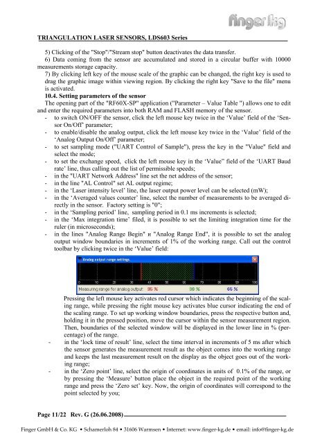
- in the lines "Analog Range Begin" и "Analog Range End", it is possible to set the analog<br />
output window boundaries in increments of 1% of the working range. Call out the control<br />
toolbar by clicking twice in the ‘Value’ field:<br />
Pressing the left mouse key activates red cursor which indicates the beginning of the scaling<br />
range, while pressing the right mouse key activates blue cursor indicating the end of<br />
the scaling range. To set up working window boundaries, press the respective button and,<br />
holding it in the pressed position, move the cursor within the sensor measurement region.<br />
Then, boundaries of the selected window will be displayed in the lower line in % (percentage)<br />
of the range.<br />
- in the ‘lock time of result’ line, select the time interval in increments of 5 ms after which<br />
the sensor generates the measurement result as the object comes into the working range<br />
and keeps the last measurement result on the display as the object goes out of the working<br />
range;<br />
- in the ‘Zero point’ line, select the origin of coordinates in units of 0.1% of the range, or<br />
by pressing the ‘Measure’ button place the object in the required point of the working<br />
range and press the ‘Zero set’ key. Now, the origin of coordinates will correspond to the<br />
point selected by you;<br />
Page 11/22<br />
<strong>Rev</strong>. G (<strong>26.06</strong>.2008)<br />
Finger GmbH & Co. KG • Schamerloh 84 • 31606 Warmsen • Internet: www.finger-kg.de • email: info@finger-kg.de