TRIANGULATION LASER SENSORS, LDS603 Series Rev. G (26.06 ...
TRIANGULATION LASER SENSORS, LDS603 Series Rev. G (26.06 ...
TRIANGULATION LASER SENSORS, LDS603 Series Rev. G (26.06 ...

Create successful ePaper yourself
Turn your PDF publications into a flip-book with our unique Google optimized e-Paper software.
<strong>TRIANGULATION</strong> <strong>LASER</strong> <strong>SENSORS</strong>, <strong>LDS603</strong> <strong>Series</strong><br />
- the request mode. In this mode, each sensor receives a frame of remote data request (Remote<br />
Frame) containing frame identifier, and responds by sending a data frame (Data Frame) with the<br />
same identifier.<br />
- the synchronization mode. When operating in the synchronization mode, each sensor automatically<br />
transmits a data frame (Data frame) together with its identifier in accordance with a specified<br />
time interval (sampling period) or in case of switching of the external synchronization output<br />
and with the selected division factor taken into account.<br />
CAN interface is used only for the reception of data. Parametrization of sensors is carried out<br />
via RS232 interface.<br />
9.2. The sensor transmits 8 byte long frame.<br />
-byte 0: type of device<br />
-byte 1: = 0 – reserved<br />
-byte 2: low byte of serial number<br />
-byte 3: high byte of serial number<br />
-byte 4: low byte of operating range<br />
-byte 5: high byte of operating range<br />
-byte 6: low byte of the result<br />
-byte 7: high byte of the result<br />
The result is calculated by the formula (1), (see par.8.11).<br />
Page 9/22<br />
10. SETUP PROGRAM<br />
10.1. The "RF60Х-SP" software package (www.riftek.com/resource/files/rf60x_sp.zip ) intended<br />
for:<br />
1) testing and demonstration of operation of <strong>LDS603</strong>-series sensors;<br />
2) setting sensor parameters;<br />
3) reception and storage of data;<br />
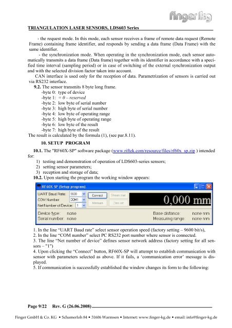
10.2. Upon starting the program the working window appears:<br />
1. In the line “UART Baud rate” select sensor operation speed (factory setting – 9600 bit/s),<br />
2. In the line “COM number” select PC RS232 port number where sensor is connected.<br />
3. The line “Net number of device” defines sensor network address (factory setting for all sensors<br />
– "1")<br />
4. Upon clicking the “Connect” button, RF60X-SP will attempt to establish communication with<br />
sensor with parameters selected as above. If it fails, a ‘communication error’ message is displayed.<br />
5. If communication is successfully established the window changes its form to the following:<br />
<strong>Rev</strong>. G (<strong>26.06</strong>.2008)<br />
Finger GmbH & Co. KG • Schamerloh 84 • 31606 Warmsen • Internet: www.finger-kg.de • email: info@finger-kg.de